EP1193134A2 - Système et procédé d'information pour un véhicule automobile - Google Patents
Système et procédé d'information pour un véhicule automobile Download PDFInfo
- Publication number
- EP1193134A2 EP1193134A2 EP01308273A EP01308273A EP1193134A2 EP 1193134 A2 EP1193134 A2 EP 1193134A2 EP 01308273 A EP01308273 A EP 01308273A EP 01308273 A EP01308273 A EP 01308273A EP 1193134 A2 EP1193134 A2 EP 1193134A2
- Authority
- EP
- European Patent Office
- Prior art keywords
- vehicle
- information
- evaluation result
- traveling
- acceleration
- Prior art date
- Legal status (The legal status is an assumption and is not a legal conclusion. Google has not performed a legal analysis and makes no representation as to the accuracy of the status listed.)
- Withdrawn
Links
- 238000000034 method Methods 0.000 title claims description 24
- 238000011156 evaluation Methods 0.000 claims abstract description 119
- 239000000446 fuel Substances 0.000 claims abstract description 30
- 230000001133 acceleration Effects 0.000 claims description 95
- 238000012545 processing Methods 0.000 description 69
- 238000005070 sampling Methods 0.000 description 34
- 230000002411 adverse Effects 0.000 description 11
- 230000000694 effects Effects 0.000 description 7
- 238000002360 preparation method Methods 0.000 description 5
- 230000000007 visual effect Effects 0.000 description 4
- 238000012790 confirmation Methods 0.000 description 3
- CURLTUGMZLYLDI-UHFFFAOYSA-N Carbon dioxide Chemical compound O=C=O CURLTUGMZLYLDI-UHFFFAOYSA-N 0.000 description 2
- 238000010586 diagram Methods 0.000 description 2
- 238000012935 Averaging Methods 0.000 description 1
- 229910002092 carbon dioxide Inorganic materials 0.000 description 1
- 239000001569 carbon dioxide Substances 0.000 description 1
- 239000000470 constituent Substances 0.000 description 1
- 230000005236 sound signal Effects 0.000 description 1
Images




Classifications
-
- G—PHYSICS
- G07—CHECKING-DEVICES
- G07C—TIME OR ATTENDANCE REGISTERS; REGISTERING OR INDICATING THE WORKING OF MACHINES; GENERATING RANDOM NUMBERS; VOTING OR LOTTERY APPARATUS; ARRANGEMENTS, SYSTEMS OR APPARATUS FOR CHECKING NOT PROVIDED FOR ELSEWHERE
- G07C5/00—Registering or indicating the working of vehicles
- G07C5/004—Indicating the operating range of the engine
-
- G—PHYSICS
- G07—CHECKING-DEVICES
- G07C—TIME OR ATTENDANCE REGISTERS; REGISTERING OR INDICATING THE WORKING OF MACHINES; GENERATING RANDOM NUMBERS; VOTING OR LOTTERY APPARATUS; ARRANGEMENTS, SYSTEMS OR APPARATUS FOR CHECKING NOT PROVIDED FOR ELSEWHERE
- G07C5/00—Registering or indicating the working of vehicles
- G07C5/08—Registering or indicating performance data other than driving, working, idle, or waiting time, with or without registering driving, working, idle or waiting time
- G07C5/0816—Indicating performance data, e.g. occurrence of a malfunction
- G07C5/0825—Indicating performance data, e.g. occurrence of a malfunction using optical means
Definitions
- the present invention relates to information offering method and apparatus for a vehicle and, more particularly, to information offering method and apparatus for a vehicle in which information is notified to the driver based on the driving situation of a vehicle.
- a vehicle driving manner depends upon a driver.
- a variety of patterns of the driving situation influences the quantity of fuel consumed by the driving.
- an object of the present invention is to provide an information offering method and apparatus for a vehicle, in which in order to assist a driver to drive a vehicle in an ecologically friendly manner, a driving situation is evaluated as to whether or not the driver drives the vehicle in an ecologically friendly manner, and then the driver is notified of the evaluation result.
- an information offering method for a vehicle including the steps of: calculating a histogram of vehicle information or a standard deviation during use of a vehicle based on at least one of vehicle information relating to fuel consumption of the vehicle, the vehicle information being output from a vehicle information detector when a predetermined time elapses after a beginning of the use of the vehicle; marking the vehicle information based on a point set in the histogram or the standard deviation; and calculating an evaluation result based on the point of each of the marked vehicle information to notify a driver of the calculated evaluation result.
- an information offering apparatus for a vehicle including: a device for setting at least one of vehicle information relating to fuel consumption of a vehicle, the vehicle information being output from a vehicle information detector when a predetermined time elapses after the beginning of use of the vehicle; a device for calculating a histogram of vehicle information or a standard deviation during the use of the vehicle based on the set vehicle information; a device for marking the vehicle information based on a point set in the histogram or the standard deviation; a device for calculating an evaluation result based on the point of each of the marked vehicle information; and a notifying device for notifying a driver of the evaluation result.
- At least one of vehicle information relating to fuel consumption of a vehicle is set, and the vehicle information is output from a vehicle information detector when a predetermined time elapses after the beginning of use of the vehicle. Then, a histogram of vehicle information or a standard deviation during the use of the vehicle is calculated based on the set vehicle information. The vehicle information is marked based on a point set in the histogram or the standard deviation, and an evaluation result is calculated based on the point of each of the marked vehicle information. Thereafter, the evaluation result is notified to a driver.
- an information offering method for a vehicle including the steps of: detecting a first vehicle speed pulse output from a vehicle speed pulse sensor during use of a vehicle and a second vehicle speed pulse output from the vehicle speed pulse sensor when a predetermined time elapses after the beginning of the use of the vehicle; calculating a histogram of vehicle information or a standard deviation based on at least one of vehicle information relating to fuel consumption of the vehicle from the first vehicle speed pulse and the second vehicle speed pulse; marking the vehicle information based on a point set in the histogram or the standard deviation; and calculating an evaluation result based on the point of each of the marked vehicle information to notify a driver of the calculated evaluation result.
- an information offering apparatus for a vehicle including: a device for detecting a first vehicle speed pulse output from a vehicle speed pulse sensor during use of a vehicle and a second vehicle speed pulse output from the vehicle speed pulse sensor when a predetermined time elapses after the beginning of the use of the vehicle; a device for calculating a histogram of vehicle information or a standard deviation based on at least one of vehicle information relating to fuel consumption of the vehicle from the first vehicle speed pulse and the second vehicle speed pulse; a device for marking the vehicle information based on a point set in the histogram or the standard deviation; a device for calculating an evaluation result based on the point of each of the marked vehicle information; and an notifying device for notifying a driver of the evaluation result.
- a first vehicle speed pulse output from a vehicle speed pulse sensor is detected during use of a vehicle, and a second vehicle speed pulse output from the vehicle speed pulse sensor is detected when a predetermined time elapses after the beginning of the use of the vehicle. Then, a histogram of vehicle information or a standard deviation is calculated based on at least one of vehicle information relating to fuel consumption of the vehicle from the first vehicle speed pulse and the second vehicle speed pulse. The vehicle information is marked based on a point set in the histogram or the standard deviation, and an evaluation result is calculated based on the point of each of the marked vehicle information. Then, the evaluation result is notified to a driver.
- the evaluation result may include an evaluation result of the driving situation of the vehicle.
- the vehicle information detector may include at least any one of a vehicle speed sensor, an acceleration sensor and a distance sensor.
- the vehicle information may include at least any one of a traveling distance, an idling time, a traveling speed and an acceleration of the vehicle.
- the marking of the vehicle information may be performed in consideration of the quantity of fuel consumption, the quantity of exhaust gas emitted, or components of the exhaust gas of the vehicle during the use of the vehicle.
- the notifying device may include at least either one of a display and a sound output unit mounted on the vehicle.
- the information offering apparatus for a vehicle is applied to a navigation system which provides route assisting information to the driver via an image or a sound.
- the information offering apparatus for a vehicle displays an image screen representing an evaluation result of a driving situation of a driver with respect to the terrestrial environment and/or provides the evaluation result to the driver in the form of sound.
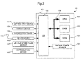
- a navigation system 10 includes an apparatus body 101 and a microcomputer including a CPU 102, a RAM 103, a ROM 104 and an input/output port (I/O) 105, wherein the constituent elements of the microcomputer are connected to each other via a bus 106 in such a manner as to freely transmit or receive a command or data.
- the RAM 103 is a backup RAM which holds therein the contents of stored information even during power-down.
- the ROM 104 stores therein programs for the processing routines described later and graphics format for displaying evaluation results of a driving situation of a driver.
- the ROM 104 may be any type of medium, such as a hard disk, that has the function of storing the programs and the graphical format for displaying the evaluation result of a driving situation of a driver.
- a backup power source 107 enables the evaluation result of the driving situation to be calculated and notified to the driver after the driver stops the engine of the vehicle. Without any backup power source, the system calculates and notifies the evaluation result up to the previous drive after the driver starts the engine at the time of the next drive. In comparison with such a system, the additional use of the backup power source 107 enables the driver to confirm the evaluation result of his or her driving situation at real time immediately after finishing the driving.
- the navigation system 10 can be connected to a local area network for a vehicle via the input/output port 105.
- a display device 108 for offering route information to the driver in the form of images
- a sound output device 109 for offering the route information to the driver in the form of sound
- a reproduction device 110 for reproducing a route information recording medium, not illustrated, such as a CD-ROM or a DVD-ROM, on which the route information is recorded.
- the display device 108 can display map information supplied from the reproduction device 110 as well as the evaluation result of the driving situation of the driver, as described later.
- the sound output device 109 converts a sound signal output from the apparatus body 101 into a drive signal for a speaker (not illustrated) additionally attached to the sound output device 109, and then outputs the drive signal.
- the sound output device 109 can notify the evaluation result of the driving situation of the driver via sound, as described later.
- the route information recording medium to be loaded in the reproduction device 110 stores therein information on a route from a current position of the vehicle to a destination, the map information geographically expressing the route and its surroundings in the form of a database, and information on the surroundings of a traveling route in association with the map information, for example, a vehicle speed limit, positions of pedestrian crossovers or railroad crossings, or types of roads such as national highways and expressways in the form of a database.
- the vehicle information detectors include a vehicle speed sensor 114, an acceleration sensor 115 and a traveling distance sensor 116.
- the vehicle speed sensor 114 is connected to a speed meter or the like of the vehicle and detects the traveling speed of the vehicle during traveling.
- the acceleration sensor 115 is adapted to detect an acceleration of the vehicle.
- the traveling distance sensor 116 is connected to a traveling distance meter or the like of the vehicle and detects the traveling distance of the vehicle.
- the vehicle information relating to the fuel consumption of the vehicle includes the traveling distance, the idling time, the traveling speed, the acceleration and the like of the vehicle.
- a setting input device 111 which is an input device for setting the evaluation condition of the driving situation with respect to the terrestrial environment by using, for example, a keyboard or a switch.
- the driver or the like sets the evaluation condition in the setting input device 111, the information on the evaluation condition is input into the RAM 103 through the input/output port 105 and the bus 106.
- a predetermined time for capturing, into the CPU 102 or the RAM 103, the vehicle information relating to the fuel consumption of the vehicle is set.
- the vehicle information relating to the fuel consumption is output from the vehicle information detectors such as the vehicle speed sensor 114, the acceleration sensor 115 and the traveling distance sensor 116.
- the CPU 102 has, in advance, a program for obtaining the vehicle information within the predetermined time.
- the RAM 103 receives a specific time value from the setting input device 111, and temporarily stores it therein.
- the CPU 102 reads out the predetermined time from the RAM 103 via the bus 106, and obtains the vehicle information from the vehicle information detectors every time the predetermined time elapses.
- the CPU 102 has several threshold values for each vehicle information, classifies the read vehicle information into parameters, and then calculates the evaluation result of the driving situation in accordance with the processing routine descried later.
- the specific threshold values are input via the setting input device 111 by the driver.
- the values thus input are temporarily stored in the RAM 103 via the input/output port 105 and the bus 106.
- the CPU 102 reads the specific threshold values input into the RAM 103 via the bus 106. Thereafter, the CPU 102 calculates the evaluation result of the driving situation in accordance with the processing routine descried later by using the specific threshold values thus input as the reference values.
- a GPS receiver 112 having a GPS antenna 113.
- the GPS receiver 112 receives radio waves from geodetic satellites in a satellite orbit via the GPS antenna 113. Thus, the latitude and longitude of the current position of the vehicle are calculated based on the received radio waves.
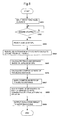
- Fig. 3 is a flowchart illustrating the processing routine for evaluating the traveling distance of the vehicle in the navigation system 10 of Fig. 1 according to the first embodiment.
- the processing routine illustrated in Fig. 3 is started in the navigation system 10 immediately after the start of the engine of the vehicle. After starting the engine, it is judged in step S301 whether or not the engine of the vehicle is stopped.
- the predetermined time for detecting traveling distance data is set to the time period from the start of the engine to the stoppage thereof. If the CPU 102 recognizes the stoppage of the engine in step S301, the routine proceeds to next step S302.
- step S302 the CPU 102 obtains the traveling distance data from the traveling distance sensor 116 via the input/output port 105 and the bus 106.
- the CPU 102 for performing arithmetic processing obtains the traveling distance data per driving of the vehicle for the first time, and become possible to use the traveling distance data.
- the traveling distance data obtained from the start of the engine to the stoppage thereof, which has been input into the CPU 102, is subjected to the arithmetic processing in step S303 in accordance with a preset routine.
- step S303 A specific example of the processing performed in step S303 will be described in reference to Fig. 4.
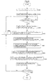
- Fig. 4 is a flowchart illustrating a specific processing routine which calculates a histogram based on the classification of the traveling distance data into parameters in the CPU 102 and calculates a composing ratio representing the frequency of each of the parameters in the histogram in step S303 of Fig. 3 and step S806 of Fig. 8 described later.
- step S402 an average traveling distance L Ave obtained by averaging the traveling distances sampled from the initial sampling to this sampling is updated.
- I is defined to be 1, wherein the reference character I represents a variable required, after step S404, for identifying one of a plurality of classified parameters to which the traveling distance data belongs to.
- next step S404 an actual identification judgement is made as to which parameter the traveling distance data L o belongs. Specifically, it is judged whether or not the traveling distance data L o is greater than L I and not larger than L I+1 , that is, it ranges within the parameter of L I ⁇ L o ⁇ L I+1 . In other words, it is first judged in this routine whether or not L 1 ⁇ L o ⁇ L 2 in sequence based on I which is defined to be 1 in step S403.
- I Max represents the total number of classified parameters; each of L 1 , L 2 , ... L I represents an upper limit value and a lower limit value of the range of each parameter, which can be changed by the setting input device 111.
- L I+1 is desirably set to a large value since the range of the maximum parameter is expressed to be L I or greater at the time of the evaluation result. For example, L 7 as L I+1 is set to be 99999 in the present embodiment.
- the composing ratio PL I (%) is updated in step S405 or step S406.
- the composing ratio PL I represents the ratio of the number of parameters with respect to the total sampling number up to this sampling.
- step S404 If it is judged in step S404 that L o belongs to the parameters from L 1 to L 2 , namely, it is judged that L 1 ⁇ L o ⁇ L 2 , the routine proceeds to step S406, in which the composing ratio PL I of the parameter ranging within L 1 ⁇ L o ⁇ L 2 is updated, and then the routine proceeds to step S407.
- step S405 the composing ratio PL I of the parameter ranging within L 1 ⁇ L o ⁇ L 2 is updated, and then the routine proceeds to step S407.
- the composing ratio PL I in the case where it is not judged in step S404 that the value L o is greater than L 1 and not greater than L 2 , namely, it is not judged that L 1 ⁇ L o ⁇ L 2 is calculated in step S405.
- next step S407 the value I is updated as I + 1.
- Step S407 in which the value I is updated is a preparation step to determine the composing ratio PL I of the next parameter in subsequent steps.
- I is updated to be 2, and then the routine proceeds to next step S408.
- step S404 it is judged based on L I ⁇ L o ⁇ L I+1 whether or not the traveling distance L o belongs to the parameters ranging within L 2 ⁇ L o ⁇ L 3 . In the present embodiment, it is judged whether or not 1 ⁇ L o ⁇ 2.
- step S404 the routine is repeated from step S404 to step S408 until I reaches I Max , that is, until the composing ratios PL I for all of the parameters are updated. Consequently, the traveling distance L o is classified in to any one range out of L 1 ⁇ L o ⁇ L 2 , L 2 ⁇ L o ⁇ L 3 , ... L IMax ⁇ L o ⁇ L IMax+1 , that is, to any one parameter.
- each of the composing ratios PL 1 , PL 2 ... PL IMax is updated in step S405 or step S406.
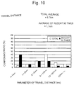
- next step S412 the histogram of the traveling distance parameter vs. the composing ratio is produced based on each of the composing ratios obtained based on the data processed in step S401 to step S409, and then it is displayed on the display device 108 in the form of an image. Furthermore, the average traveling distance obtained in step S402 is also displayed on the display device 108 in the form of an image together with the histogram of the traveling distance parameter vs. the composing ratio.
- the CPU 102 outputs the image data to the display device 108 through the bus 106 and the input/output port 105, and then the display device 108 displays the data in the form of the images.
- Fig. 4 illustrates the processing routine for making the histogram of the traveling distance parameter vs. the composing ratio with respect to all of the traveling distance data sampled up to now
- the histogram of the traveling distance parameter vs. the composing ratio may be produced for the traveling distance data limited from this sampling to the predetermined number of past samplings.
- step S401 The processing from step S401 to step S409 is performed in the same manner as that in Fig. 4. Upon completion of step S409, the routine proceeds to step S410.
- step S410 it is judged whether or not the sampling number N updated in step S409 is equal to N Max , wherein N Max represents the sampling number inclusive of this sampling, set in the case where the results of traveling distance data of the recent sampling number N Max are obtained with a limitation, and it can be freely set by the user using the setting input device 111.
- N Max represents the sampling number inclusive of this sampling, set in the case where the results of traveling distance data of the recent sampling number N Max are obtained with a limitation, and it can be freely set by the user using the setting input device 111.
- Setting N Max enables the composing ratios of the late sampling number N Max to be obtained in addition to the total composing ratio of the traveling times.
- N Max is set to be 50. Consequently, in step S412, the result of recent 50 traveling distance data can be obtained in addition to the total traveling distance data up to now.
- step S411 the routine proceeds to step S412.
- step S412 the routine proceeds to step S412.
- the recent N Max data are updated every time the vehicle travels, thereby obtaining the composing ratios PL 1 .for the recent N Max .
- next step S412 the same processing as that in Fig. 4 is performed, thus making a histogram of the traveling distance parameter vs. the composing ratio with respect to the recent N Max traveling distance data inclusive of this data.
- Fig. 10 illustrates an example of a histogram of the traveling distance parameter vs. the composing ratio and the average traveling distance, in which N Max is set to be 50. Since the histogram of the traveling distance parameter vs. the composing ratio and the average traveling distance are displayed, the driver can confirm his or her driving situation in detail. Upon completion of step S412, the routine proceeds to step S304 of Fig. 3, in which the marking is performed.
- next step S304 the obtained traveling distance data are marked. Specifically, the composing ratio of the traveling distance of the vehicle is marked with respect to each of conditions of the composing ratio based on a preset point.
- a method for marking the composing ratio of the traveling distance in step S304 will be explained with reference to Table 1.
- the composing ratio of the traveling distance is marked in accordance with an evaluation criterion of Table 1 based on the histogram of the traveling distance parameter vs. the composing ratio obtained by the processing routine illustrated in Fig. 4 or Fig. 14.
- the evaluation criterion of Table 1 has been previously stored in the RAM 103.
- the CPU 102 reads information on the evaluation criterion from the RAM 103, and then executes the marking.
- an idling time ratio, a composing ratio of the traveling speed and an acceleration standard deviation, described later, are comprehensively marked in next step S305, thus judging the driving situation.
- the comprehensive evaluation of the driving situation of the driver with respect to the terrestrial environment is calculated by adding the marked point to the information on each of the vehicles.
- the calculation of the comprehensive evaluation is performed by the CPU 102.
- the result of the calculated evaluation is output from the CPU 102, and then is notified to the driver by the display device 108 or the sound output device 109.
- a grade A is set for the total point of 95 or more
- a grade B is set for the total point ranging from 90 to 95
- a grade C is set for total point ranging from 80 to 90
- a grade D is set for the total point ranging from 60 to 80
- a grade E is set for the total point of less than 60.
- the evaluation result is grade D or E
- a further effect can be expected by configuring the system such that the display device 108 or the sound output device 109 calls visual or auditory attention of the driver.
- the assumed patterns may be previously stored in the ROM 104, and the system may advise the driver how to improve their driving situation if the evaluation result is the grade D or E.
- Fig. 5 is a flowchart illustrating the processing routine for evaluating the idling time, the traveling speed and the acceleration of the vehicle in the navigation system 10 of Fig. 1 according to the first preferred embodiment.
- the processing routine of Fig. 5 is implemented in the navigation system 10. After the start of the engine, it is judged in step S501 whether or not a predetermined time set previously has elapsed.
- the predetermined time signifies a unit time which is required for obtaining the traveling speed and the acceleration of the vehicle and has been stored in the CPU 102 in advance.
- the processing routine proceeds to next step S502.
- step S502 the CPU 102 obtains the traveling speed data and the acceleration data from the vehicle speed sensor 114 and the acceleration sensor 115, respectively, via the input/output port 105 and the bus 106.
- the traveling speed data and the acceleration data during the use of the vehicle are input into the CPU 102 which performs arithmetic processing.
- the traveling speed data and the acceleration data, which the CPU 102 obtained, are subjected to the arithmetic processing in step S503 in accordance with a preset routine.
- Fig. 6 is a flowchart illustrating a specific processing routine for calculating a histogram based on the classification of the traveling speed data into parameters in the CPU 102 so as to calculate a composing ratio representing the frequency of each of the parameters in the histogram in step S503 of Fig. 5 and step S907 of Fig. 9, described later, and further, a specific processing routine for calculating an idling time ratio.
- step S602 the idling time N idl is updated to N idl + 1 in step S602, and then the routine proceeds to step S603.
- step S603 an idling time ratio R idl is updated to N idl / (N + 1) based on N idl updated in step S602.
- the idling time ratio obtained in this step is to be evaluated as described later.
- the routine proceeds to step S604.
- reference character N designates the times of traveling speed data sampled from the start of the processing routine of Fig. 5 to the previous sampling.
- step S604 an average traveling speed V Ave of the traveling speeds for a certain period of time is updated.
- the certain period of time can be freely set based on N Max , described later. Calculation of the average traveling speed V Ave enables the notification of an average speed of the vehicle to the driver at real time.
- next step S605 I is set to 1, wherein reference character I represents a variable required for identifying one of the classified parameters to which the traveling speed data belongs in steps after S606.
- step S606 an actual identification judgement is made as to which parameter the traveling speed data V o actually belongs. Specifically, it is judged whether or not the traveling speed data V o is greater than V I and not greater than V I+1 , that is, it ranges within parameters of V I ⁇ V o ⁇ V I+1 . In other words, it is first judged in this routine whether or not V 1 ⁇ V o ⁇ V 2 based on I which is set to be 1 in step S605.
- I Max represents the total number of classified parameters.
- Each of V 1 , V 2 , ... V I represents an upper limit value and a lower limit value of the range of each of the parameters, which can be varied by the setting input device 111.
- V I+1 is desirably set to a large value since the range of the maximum parameter is expressed to be V I or greater at the time of the evaluation.
- V 9 as V I+1 is set to be 9999 in the present embodiment.
- a composing ratio PV I (%) of V 1 is updated in step S607 or step S608.
- the composing ratio PV I represents the ratio of the number of parameters with respect to the total sampling number up to this sampling.
- step S606 If it is judged in step S606 that V o belongs to the parameters from V 1 to V 2 , namely, it is judged that V 1 ⁇ V o ⁇ V 2 , the routine proceeds to step S608, in which the composing ratio PV I of the parameter ranging within V 1 ⁇ V o ⁇ V 2 is updated, and then the routine proceeds to step S609.
- step S608 In contrast, unless it is judged that V o belongs to the parameters from V 1 to V 2 , namely, unless it is judged that V 1 ⁇ V o ⁇ V 2 , the routine proceeds to step S607. In the same manner, the composing ratio PV I of the parameter ranging within V 1 ⁇ V o ⁇ V 2 is updated, and then the routine proceeds to step S609.
- the composing ratio PV I in the case where it is not judged in step S606 that the value V o is greater than V 1 and not greater than V 2 , namely, it is not judged that V 1 ⁇ V o ⁇ V 2 is calculated in step S607.
- next step S609 the value I is updated as I + 1.
- Step 609 in which the value I is updated is a preparation step to determine the composing ratio PL I of the next parameter from a next step onward. In this routine in the present embodiment, I is updated to be 2, and then the routine proceeds to next step S610.
- step S606 it is judged based on V I ⁇ V o ⁇ V I+1 whether or not the traveling speed V o belongs to the parameters ranging within V 2 ⁇ V o ⁇ V 3 . In the present embodiment, it is judged whether or not 5 ⁇ V o ⁇ 20.
- step S606 the routine is repeated from step S606 to step S610 until I reaches I Max , that is, until the composing ratios PV I of all of the parameters are updated. Consequently, the traveling speed V o belongs to any one range out of V 1 ⁇ V o ⁇ V 2 , V 2 ⁇ V o ⁇ V 3 , ... V IMax ⁇ V o ⁇ V IMax+1 , that is, to any one parameter. Thus, each of the composing ratios PV 1 , PV 2 ... PV IMax is updated in step S607 or step S608.
- step S612 it is judged whether or not the sampling number N updated in step S611 is N Max , wherein N Max represents a number which is set to obtain an average traveling speed V Ave of recent sampling number N Max inclusive of this sampling. In other words, N Max represents a number which is set to obtain an average traveling speed V Ave for a certain period of time.
- the certain period of time can be actually obtained by multiplying a predetermined time required for obtaining the traveling speed illustrated in step S501 of Fig. 5 by the number N Max . Consequently, the number N Max itself can be referred to as the certain period of time.
- the number N Max can be freely set using the setting input device 111 by the driver. Varying the number N Max enables a time resolution of a traveling speed monitor to be freely varied.
- This step is a preparation step to sequentially update the average traveling speed V Ave within the set certain period of time.
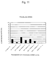
- next step S614 the histogram of the traveling distance parameter vs. the composing ratio is made based on each of the composing ratios obtained from the data processed in step S601 to step S613, and the histogram is displayed on the display device 108 in the form of an image. Furthermore, the average traveling speed V Ave obtained in step S604 is also displayed on the display device 108 in the form of an image as a traveling speed monitor.
- the traveling speed monitor signifies an image in which the average traveling speed V Ave with respect to the time after the start of the driving during the traveling is displayed in time sequence.
- the CPU 102 In the case where each of the images is displayed on the display device 108, the CPU 102 outputs the data to the display device 108 through the bus 106 and the input/output port 105, and the display device 108 displays the data in the form of an image.
- Fig. 11 illustrates an example of a histogram of the traveling speed parameter vs. the composing ratio and the average traveling speed
- Fig. 12 illustrates an example of the traveling speed monitor.
- a time when the traveling speed is 0 signifies an idling time.
- the driver can confirm his or her driving situation in detail.
- step S614 the routine proceeds to step S504 of Fig. 5.
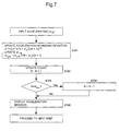
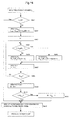
- Fig. 7 is a flowchart illustrating a specific processing routine in which the CPU 102 calculates an acceleration standard deviation based on the acceleration data in step S503 of Fig. 5 and step S907 of Fig. 9 in a second embodiment described later.
- step S701 an acceleration standard deviation ⁇ is updated based on the acceleration ⁇ o read by the CPU 102. It is found that the greater the acceleration standard deviation ⁇ is, the higher the frequency of fast acceleration or deceleration.
- the reference character N designates the number of acceleration data sampled from the start of the processing routine of Fig. 5 to the previous sampling.
- step S701 an average acceleration ⁇ Ave of the accelerations for a certain period of time is also updated based on the acceleration ⁇ o read by the CPU 102.
- the certain period of time can be freely set based on N Max described later. Calculation of the average acceleration ⁇ Ave enables the average acceleration of the vehicle to be notified to the driver at real time.
- the processing routine proceeds to step S702.
- step S703 it is judged whether or not the sampling number N updated in step S702 is equal to N Max , wherein N Max represents a number which is set to obtain the average acceleration ⁇ Ave of the recent sampling number N Max inclusive of this sampling. In other words, N Max represents a number which is set to obtain the average acceleration ⁇ Ave for a certain period of time.
- the certain period of time can be actually obtained by multiplying a predetermined time required for obtaining the acceleration illustrated in step S501 of Fig. 5 by the number N Max . Consequently, the number N Max itself can be referred to as the certain period of time.
- the number N Max can be freely set in the setting input device 111 by the driver. Varying the number N Max enables a time resolution of an acceleration monitor to be freely varied.
- This step is a preparation step to sequentially update the average acceleration ⁇ Ave within the set certain period of time.
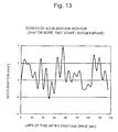
- next step S705 the average acceleration ⁇ Ave based on the data processed in step S701 to step S704 is displayed on the display device 108 in the form of an image as an acceleration monitor.
- the acceleration monitor signifies an image in which the average acceleration ⁇ Ave with respect to the time after the start of the driving during the traveling is displayed in time sequence.
- the CPU 102 outputs the data to the display device 108 through the bus 106 and the input/output port 105, and then the display device 108 displays the data in the form of an image.
- Fig. 13 illustrates an example of the acceleration monitor. Since the acceleration monitor is displayed, the driver can confirm his or her driving situation in detail. Upon completion of the processing in step S705, the routine proceeds to step S504 of Fig. 5.
- the composing ratio of the traveling speed of the vehicle is marked with respect to each of conditions of the composing ratio based on a preset point.
- the acceleration standard deviation of the vehicle is marked with respect to each of conditions of the acceleration standard deviation based on a preset point.
- the idling time ratio of the vehicle is marked with respect to each of conditions of the idling time ratio based on a preset point.
- the idling time ratio is marked in accordance with an evaluation criterion of Table 2 based on the data on the idling time ratio obtained by the processing routine illustrated in Fig. 6.
- the evaluation criterion of Table 2 has been previously stored in the RAM 103.
- information on the evaluation criterion is output from the RAM 103, and then the CPU 102 executes the marking.
- Fuel consumption is increased if the idling time is long, thereby exerting an adverse influence on the terrestrial environment. Consequently, it is designed such that the lower the idling time ratio is, the higher the point is.
- the idling time ratio is calculated for marking.
- a method may be used that the total idling time is calculated, an evaluation criterion for marking an idling time, like Table 2, is set, and thus the total idling time is marked in accordance with the evaluation criterion.
- Idling time ratio: Full mark 25 Evaluation Point 50% or more 0 40% to 50% 5 30% to 40% 10 20% to 30% 15 10% to 20% 20 0% to 10% 25
- the composing ratio of the traveling speed is marked in accordance with an evaluation criterion of Table 3 based on the histogram of the traveling speed parameter vs. the composing ratio obtained by the processing routine illustrated in Fig. 6.
- the evaluation criterion of Table 3 has been previously stored in the RAM 103.
- the CPU 102 reads information on the evaluation criterion from the RAM 103, and then executes the marking.
- Each of the vehicles has an efficient traveling speed peculiar to itself, at which it can travel at a low engine speed with low fuel consumption. It may be designed such that a higher point is marked as the traveling speed ratio becomes higher. Since the efficient traveling speed is varied according to the type of vehicle, the evaluation criterion per type of vehicle is variably set by using the setting input device 111.
- the acceleration standard deviation is marked in accordance with an evaluation criterion of Table 4 based on the data on the acceleration standard deviation obtained by the processing routine illustrated in Fig. 7.
- the evaluation criterion of Table 4 has been previously stored in the RAM 103.
- the CPU 102 reads information on the evaluation criterion from the RAM 103, and then executes the marking.
- the fast acceleration unnecessarily increases an engine speed, and thus fuel consumption is increased, thereby exerting an adverse influence on the terrestrial environment. It is designed such that a higher point is marked as the acceleration standard deviation becomes smaller.
- the acceleration standard deviation is calculated for marking.
- a method may be used that the composing ratio of the acceleration is calculated in the same manner as the traveling speed, an evaluation criterion for marking the composing ratio of the acceleration, like Table 4, is set, and thus the composing ratio of the acceleration is marked in accordance with the evaluation criterion.
- next step S505 the driving situation is judged by comprehensively marking the traveling distance composing ratio, which is obtained till the previous traveling, in addition to the traveling speed composing ratio, the acceleration standard deviation and the idling time ratio.
- the comprehensive evaluation of the driving situation of the driver with respect to the terrestrial environment is calculated by adding the marked point to the information on each of the vehicles.
- the calculation of the comprehensive evaluation is performed by the CPU 102.
- the result of the calculated evaluation is output from the CPU 102, and then is notified to the driver by the display device 108 or the sound output device 109.
- a grade A in the case of a total point of 95 or more a grade B in the case of a total point ranging from 90 to 95, a grade C in the case of a total point ranging from 80 to 90, a grade D in the case of a total point ranging from 60 to 80, and a grade E in the case of a total point of less than 60, as an example of the comprehensive evaluation.
- the driver is notified of such a result of the comprehensive evaluation, and can recognize his or her comprehensive driving situation with respect to the terrestrial environment. This can assist the driver to drive the vehicle in an ecologically friendly manner.
- a further effect can be expected by configuring a system such that the display device 108 or the sound output device 109 calls visual or auditory attention of the driver.
- assumed patterns have been previously stored in the ROM 104, the driver may be advised how to cope with his or her driving situation so as to improve the driving situation in the case of the evaluation result of D or E.
- next step S507 it is judged whether or not the engine of the vehicle is stopped.
- the engine stoppage leads to completion of inputting of the traveling speed data and the acceleration data into the CPU 102.
- the present processing routine comes to an end.
- the processing routine returns to step S501, and then repeats from step S501 to step S507.
- the processing routine is repeated.
- the evaluation result is continuously updated, and then is notified to the driver by the display device 108 or the sound output device 109.
- the driving situation is judged by comprehensively marking the respective points of the traveling distance composing ratio, the traveling speed composing ratio, the acceleration standard deviation and the idling time.
- the marking result of each of the vehicle information may be notified to the driver by the display device 108 or the sound output device 109.
- a vehicle speed pulse sensor 117 may be connected to an input/output port 105 in a navigation system 20 illustrated in Fig. 2 in place of the vehicle speed sensor 114, the acceleration sensor 115 and the traveling distance sensor 116 illustrated in Fig. 1.
- a traveling speed, an acceleration and a traveling distance during traveling of a vehicle can be detected based on a vehicle speed pulse output from the vehicle speed pulse sensor 117.
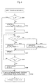
- Fig. 8 is a flowchart illustrating the processing routine for evaluating the traveling distance of the vehicle in the navigation system 20 of Fig. 2 according to the second embodiment.
- the processing routine illustrated in Fig. 8 is started in the navigation system 20 simultaneously with the start of the engine of the vehicle. Immediately after starting the engine, the vehicle speed pulse data output from the vehicle speed pulse sensor 117 is input as a Pulse (1) into the RAM 103 via the input/output port 105 and a bus 106 in step S801.
- the Pulse (1) is the vehicle speed pulse which is output from the vehicle speed pulse sensor 117 at the time of the start of the engine.
- the Pulse (1) is data required for calculating a traveling distance in each driving of the vehicle, and therefore it is input into and then stored in the RAM 103.
- step S802 It is judged in step S802 whether or not the engine of the vehicle is stopped.
- the time when the stoppage of the engine is detected signifies a lapse of a predetermined time when traveling distance data is detected.
- the routine proceeds to next step S803.
- step 803 the CPU 102 reads, as a Pulse (2), the vehicle speed pulse data output from the vehicle speed pulse sensor 117 via the input/output port 105 and the bus 106.
- the Pulse (2) is a vehicle speed pulse to be output from the vehicle speed pulse sensor 117 immediately after the stoppage of the engine.
- the Pulse (2) is also the data required for calculating the traveling distance data per driving of the vehicle.
- the times of the start of the engine and the stoppage of the engine are set as predetermined times which are input by the CPU 102.
- next step S804 the CPU 102 calculates a difference between the Pulse (1) and the Pulse (2), i.e., a ⁇ Pulse.
- the CPU 102 reads, from the RAM 103, the Pulse (1) stored in the RAM 103. In this manner, the ⁇ Pulse is calculated.
- the CPU 102 calculates a traveling distance based on the ⁇ Pulse.
- the traveling distance is calculated by multiplying a distance constant, which is peculiarly set for each of the vehicles, by the ⁇ Pulse.
- the distance constant signifies a circumference of a wheel of the vehicle. Namely, the distance constant indicates the distance that the vehicle advances by one rotation of its wheel.
- the traveling distance data per driving is calculated by multiplying the total number of rotations of an axle of the vehicle during traveling, that is, the ⁇ Pulse by the distance constant.
- the traveling distance data calculated in step S805 is classified into parameters corresponding to the data out of preset parameters in the CPU 102 in next step S806, and thus the composing ratio of each of the parameters is updated.
- classification is performed in accordance with the same routine as that in step S303 of Fig. 3 in the first embodiment, that is, in accordance with the processing routine illustrated in Fig. 4 or Fig. 14.
- next step S807 the obtained traveling distance data is marked. Specifically, the composing ratio of the traveling distance of the vehicle is marked with respect to each of conditions of the composing ratio based on a preset point.
- the explanation will be made on an example of a method for marking the composing ratio of the traveling distance in step S807.
- the composing ratio of the traveling distance is marked in accordance with the evaluation criterion of Table 1 based on the histogram of the traveling distance parameter vs. the composing ratio obtained by the processing routine illustrated in Fig. 4 or Fig. 14 in the same manner as in the first embodiment.
- the evaluation criterion of Table 1 has been previously stored in the RAM 103.
- the CPU 102 reads information on the evaluation criterion from the RAM 103, and then executes the marking.
- the comprehensive evaluation of the driving situation of the driver with respect to the terrestrial environment is calculated by adding the marked point to the information on each of the vehicles.
- the calculation of the comprehensive evaluation is performed by the CPU 102.
- the result of the calculated evaluation is output from the CPU 102, and then is notified to the driver by the display device 108 or the sound output device 109.
- a grade A for the total point of 95 or more a grade B for the total point ranging from 90 to 95, a grade C for the total point ranging from 80 to 90, a grade D for the total point ranging from 60 to 80, and a grade E for the total point of less than 60 as an example of the comprehensive evaluation.
- the driver is notified of such a result of the comprehensive evaluation, and thus can recognize his or her comprehensive driving situation with respect to the terrestrial environment. This can assist the driver to drive the vehicle in an ecologically friendly manner.
- a further effect can be expected by configuring a system such that the display device 108 or the sound output device 109 calls visual or auditory attention of the driver.
- assumed patterns may be previously stored in the ROM 104 so that the driver may be advised how to cope with his or her driving situation so as to improve the driving situation in the case of the evaluation result of D or E.
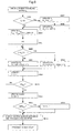
- Fig. 9 is a flowchart illustrating the processing routine for evaluating the traveling speed, the acceleration and the idling time of the vehicle in the navigation system 20 of Fig. 2 according to the second preferred embodiment.
- n is defined to be 1 in step S901.
- n is a variable representing the input order of the Pulse, which is output from the vehicle speed pulse sensor 117, and then input into the navigation system 20.
- step S902 the vehicle speed pulse data output from the vehicle speed pulse sensor 117 is input, as a Pulse (n), into the RAM 103 via the input/output port 105 and the bus 106.
- n 1
- the vehicle speed pulse data is input as the Pulse (1).
- the Pulse (1) is data required for calculating the traveling speed and the acceleration of the vehicle, and therefore it is input into and then stored in the RAM 103.
- next step S903 It is judged in next step S903 whether or not a predetermined time set previously elapses.
- the predetermined time signifies a unit time required for obtaining the traveling speed and the acceleration of the vehicle.
- step S904 the CPU 102 reads the vehicle speed pulse data, as a Pulse (n+1), from the vehicle speed pulse sensor 117 via the input/output port 105 and the bus 106.
- n 1
- the vehicle speed pulse data is input as the Pulse (2).
- the Pulse (2) is data required for calculating a ⁇ Pulse (2), which is needed in the following steps, and therefore it is input into and then stored in the RAM 103.
- the Pulse (2) is also the data required for calculating the traveling speed and the acceleration of the vehicle.
- the CPU 102 calculates a traveling speed and an acceleration based on the ⁇ Pulse (n).
- the traveling distance is calculated by multiplying a distance constant, which is set peculiarly to each of the vehicles, by the ⁇ Pulse (n).
- the distance constant signifies a circumference of a wheel of the vehicle.
- the traveling distance data per unit time is calculated by multiplying the total number of rotations of an axle of the vehicle during traveling, that is, the ⁇ Pulse (n) by the distance constant.
- the traveling speed is calculated by differentiating the calculated traveling distance with respect to a unit time, and further the acceleration is calculated by differentiating the calculated traveling speed with respect to the unit time.
- the traveling speed data calculated in step S906 is classified into parameters corresponding to the data out of preset parameters in the CPU 102 in next step S907, and thus the composing ratio of each of the parameters is updated.
- classification is performed in accordance with the same routine as that in step S503 of Fig. 5 in the first embodiment, that is, in accordance with the processing routine illustrated in Fig. 6.
- an idling time ratio is updated in accordance with the processing routine illustrated in Fig. 6 in the same manner as in the first embodiment.
- the CPU 102 updates an acceleration standard deviation in next step S907 based on the acceleration data calculated in step S906.
- the acceleration standard deviation is processed in accordance with the same routine as that in step S503 in the first embodiment, that is, in accordance with the processing routine illustrated in Fig. 7.
- the obtained traveling speed data, acceleration data and idling data are marked in next step S908.
- the traveling speed data the composing ratio of the traveling speed of the vehicle is marked with respect to each of conditions of the composing ratio based on a preset point.
- the acceleration standard deviation of the vehicle is marked with respect to each of conditions of the acceleration standard deviation based on a preset point.
- the idling time ratio of the vehicle is marked with respect to each of conditions of the idling time ratio based on a preset point.
- the idling time ratio is marked in accordance with the evaluation criterion of Table 2 based on the data on the idling time ratio obtained by the processing routine illustrated in Fig. 6 in the same manner as in the first embodiment.
- the evaluation criterion of Table 2 has been previously stored in the RAM 103.
- information on the evaluation criterion is output from the RAM 103, and then the CPU 102 executes the marking.
- Fuel consumption is increased if the idling time is long, thereby exerting an adverse influence on the terrestrial environment. Consequently, it is designed such that the lower the idling time ratio is, the higher the point is.
- the composing ratio of the traveling speed is marked in accordance with the evaluation criterion of Table 3 based on the histogram of the traveling speed parameter vs. the composing ratio obtained by the processing routine illustrated in Fig. 6 in the same manner as in the first embodiment.
- the evaluation criterion of Table 3 has been previously stored in the RAM 103.
- the CPU 102 reads information on the evaluation criterion from the RAM 103, and then executes the marking.
- Each of the vehicles has an efficient traveling speed peculiar to itself, at which it can travel at a low engine speed with low fuel consumption. It may be designed such that a higher point is marked as the traveling speed ratio at that traveling speed becomes higher. Since the traveling speed varies according to the type of vehicle, the evaluation criterion per type of vehicle is variably set by using a setting input device 111.
- the acceleration standard deviation is marked in accordance with the evaluation criterion of Table 4 based on the data on the acceleration standard deviation obtained by the processing routine illustrated in Fig. 7 in the same manner as in the first embodiment.
- the evaluation criterion of Table 4 has been previously stored in the RAM 103.
- the CPU 102 reads information on the evaluation criterion from the RAM 103, and then executes the marking.
- the fast acceleration increases an engine speed more than needed, and thus fuel consumption is increased, thereby exerting an adverse influence on the terrestrial environment. It is designed such that a higher point is marked as the acceleration standard deviation becomes smaller.
- next step S909 the driving situation is judged by comprehensively marking the traveling distance composing ratio, which is obtained till the previous traveling, in addition to the traveling speed composing ratio, the acceleration standard deviation and the idling time ratio.
- the comprehensive evaluation of the driving situation of the driver with respect to the terrestrial environment is calculated by adding the marked point to the information on each of the vehicles.
- the calculation of the comprehensive evaluation is performed by the CPU 102.
- the result of the calculated evaluation is output from the CPU 102, and then is notified to the driver by the display device 108 or the sound output device 109.
- a grade A for the total point of 95 or more a grade B for the total point ranging from 90 to 95, a grade C for the total point ranging from 80 to 90, a grade D for the total point ranging from 60 to 80, and a grade E for the total point of less than 60 as an example of the comprehensive evaluation.
- the driver is notified of such a result of the comprehensive evaluation, and thus can recognize his or her comprehensive driving situation with respect to the terrestrial environment. This can assist the driver to drive the vehicle in an ecologically friendly manner.
- a further effect can be expected by configuring a system such that the display device 108 or the sound output device 109 calls visual or auditory attention of the driver.
- assumed patterns may be previously stored in the ROM 104 so that the driver may be advised how to cope with his or her driving situation so as to improve the driving situation in the case of the evaluation result of D or E.
- next step S911 it is judged whether or not the engine of the vehicle is stopped.
- the engine stoppage leads to completion of inputting of the vehicle speed pulse data into the CPU 102.
- the present processing routine comes to an end.
- the processing routine repeats from step 903 to step S911.
- the value n in the Pulse and the ⁇ Pulse also is updated from a next step onward.
- the processing routine is repeated.
- the evaluation result is continuously updated, and then is notified to the driver by the display device 108 or the sound output device 109.
- the driving situation is judged by comprehensively marking the respective points of the traveling distance composing ratio, the traveling speed composing ratio, the acceleration standard deviation and the idling time.
- the marking result of each of the vehicle information may be notified to the driver by the display device 108 or the sound output device 109.
- the present invention is not restricted to the above-described embodiments as long as a system includes a method in which the driving situation of the driver with respect to the terrestrial environment is evaluated, and then it is notified to the driver via the image display or the sound.
- the conditions of the parameters of the information on each of the vehicles, the point set for the parameter and the point set for the comprehensive evaluation have been described in the present embodiments, the conditions are not restricted to those in the present embodiments as long as a method is used in which the driving situation of the driver with respect to the terrestrial environment is evaluated, and then it is notified to the driver via the image display or the sound.
- the conditions may be set according to the type of vehicle or the environment in which the vehicle is driven.
- the RAM and the ROM are configured independently of each other inside of the navigation system in the above-described embodiments, it is understood that the ROM may be replaced with the RAM, or that the RAM and the ROM may be configured integrally with each other.
- the driving situation is evaluated as to whether or not the driver drives the vehicle in an ecologically friendly manner, and then the driver is notified of the evaluation result.
- the driver can recognize the ecologically friendly driving manner, and is assisted to drive the vehicle in an ecologically friendly manner.
Landscapes
- Physics & Mathematics (AREA)
- General Physics & Mathematics (AREA)
- Navigation (AREA)
- Traffic Control Systems (AREA)
- Time Recorders, Dirve Recorders, Access Control (AREA)
- Instrument Panels (AREA)
Applications Claiming Priority (2)
| Application Number | Priority Date | Filing Date | Title |
|---|---|---|---|
| JP2000298389A JP2002104023A (ja) | 2000-09-29 | 2000-09-29 | 車両用情報提供方法及び装置 |
| JP2000298389 | 2000-09-29 |
Publications (2)
| Publication Number | Publication Date |
|---|---|
| EP1193134A2 true EP1193134A2 (fr) | 2002-04-03 |
| EP1193134A3 EP1193134A3 (fr) | 2003-01-08 |
Family
ID=18780358
Family Applications (1)
| Application Number | Title | Priority Date | Filing Date |
|---|---|---|---|
| EP01308273A Withdrawn EP1193134A3 (fr) | 2000-09-29 | 2001-09-27 | Système et procédé d'information pour un véhicule automobile |
Country Status (3)
| Country | Link |
|---|---|
| US (1) | US20020062191A1 (fr) |
| EP (1) | EP1193134A3 (fr) |
| JP (1) | JP2002104023A (fr) |
Cited By (4)
| Publication number | Priority date | Publication date | Assignee | Title |
|---|---|---|---|---|
| DE10241922A1 (de) * | 2002-09-10 | 2004-03-18 | Bayerische Motoren Werke Ag | Fahrerassistenzsystem für ein Strassenfahrzeug |
| WO2009040357A1 (fr) * | 2007-09-25 | 2009-04-02 | Continental Automotive Gmbh | Procédé et dispositif pour éditer des données d'un tachygraphe |
| WO2009125178A3 (fr) * | 2008-04-07 | 2009-12-30 | The Neutral Group Limited | Appareil et procédé pour obtenir une valeur associée à des émissions de carbone résultant du fonctionnement d'un véhicule |
| EP2284801A1 (fr) * | 2009-08-07 | 2011-02-16 | Aisin Aw Co., Ltd. | Dispositif de diagnostic d'opérations de véhicule, procédé, programme informatique et support lisible sur ordinateur |
Families Citing this family (17)
| Publication number | Priority date | Publication date | Assignee | Title |
|---|---|---|---|---|
| JP2006160191A (ja) * | 2004-12-10 | 2006-06-22 | Pioneer Electronic Corp | 情報表示装置、情報表示方法および情報表示プログラム |
| JP2006188114A (ja) * | 2005-01-04 | 2006-07-20 | Kenwood Corp | 車載装置 |
| JP4736913B2 (ja) | 2005-09-27 | 2011-07-27 | 株式会社デンソー | エコドライブシステム |
| JP2007102658A (ja) * | 2005-10-07 | 2007-04-19 | Omron Corp | 車両運行管理システム |
| US20070143002A1 (en) * | 2005-12-21 | 2007-06-21 | Crowell Thomas J | System for evaluating and improving driving performance and fuel efficiency |
| JP2007278911A (ja) * | 2006-04-10 | 2007-10-25 | Wataru Horikawa | エコドライブ支援装置、カーナビゲーションシステム及びエコドライブ支援プログラム |
| JP4475251B2 (ja) * | 2006-04-25 | 2010-06-09 | トヨタ自動車株式会社 | 車両環境サービスシステム |
| JP2008174096A (ja) * | 2007-01-18 | 2008-07-31 | Denso Corp | 車両用表示装置 |
| JP5133137B2 (ja) | 2008-05-29 | 2013-01-30 | 富士通テン株式会社 | 運転評価装置および運転評価方法 |
| JP2010031811A (ja) * | 2008-07-30 | 2010-02-12 | Fujitsu Ten Ltd | 省燃費運転診断装置、車載システム、駆動制御装置および省燃費運転診断プログラム |
| JP5243910B2 (ja) * | 2008-09-29 | 2013-07-24 | 本田技研工業株式会社 | 燃費向上のための運転操作を運転者に指導するための装置 |
| JP4954173B2 (ja) * | 2008-09-30 | 2012-06-13 | 本田技研工業株式会社 | 燃費向上のための運転操作を運転者に指導するための装置 |
| US8055437B2 (en) * | 2009-03-17 | 2011-11-08 | Ford Global Technologies, Llc | CO2 information display and method |
| JP5686520B2 (ja) * | 2010-02-16 | 2015-03-18 | 矢崎総業株式会社 | 車両用出力装置 |
| US8543308B2 (en) | 2010-04-19 | 2013-09-24 | GM Global Technology Operations LLC | Systems and methods for communicating optimal driving information |
| JP5760852B2 (ja) * | 2011-03-10 | 2015-08-12 | 株式会社デンソー | 省燃費運転支援システム |
| JP5860676B2 (ja) * | 2011-11-17 | 2016-02-16 | 矢崎エナジーシステム株式会社 | タクシーメータ |
Family Cites Families (4)
| Publication number | Priority date | Publication date | Assignee | Title |
|---|---|---|---|---|
| US4463427A (en) * | 1979-07-18 | 1984-07-31 | Renault Vehicules Industriels | Road transportation vehicle drive assist process and apparatus |
| US4408293A (en) * | 1980-12-04 | 1983-10-04 | Jack Avins | Automotive control systems for improving fuel consumption |
| DE3526671A1 (de) * | 1985-07-25 | 1987-01-29 | Man Technologie Gmbh | Antriebsstrang fuer kraftfahrzeuge |
| US5544056A (en) * | 1995-01-23 | 1996-08-06 | Seireg; Ali A. | Computerized control of automobile speed |
-
2000
- 2000-09-29 JP JP2000298389A patent/JP2002104023A/ja not_active Withdrawn
-
2001
- 2001-09-27 EP EP01308273A patent/EP1193134A3/fr not_active Withdrawn
- 2001-10-01 US US09/965,887 patent/US20020062191A1/en not_active Abandoned
Non-Patent Citations (1)
| Title |
|---|
| None |
Cited By (8)
| Publication number | Priority date | Publication date | Assignee | Title |
|---|---|---|---|---|
| DE10241922A1 (de) * | 2002-09-10 | 2004-03-18 | Bayerische Motoren Werke Ag | Fahrerassistenzsystem für ein Strassenfahrzeug |
| US7684907B2 (en) | 2002-09-10 | 2010-03-23 | Bayerische Motoren Werke Aktiengesellschaft | Driver assistance system for a road vehicle |
| WO2009040357A1 (fr) * | 2007-09-25 | 2009-04-02 | Continental Automotive Gmbh | Procédé et dispositif pour éditer des données d'un tachygraphe |
| US8353587B2 (en) | 2007-09-25 | 2013-01-15 | Continental Automotive Gmbh | Method and device for dispensing data from a tachograph |
| WO2009125178A3 (fr) * | 2008-04-07 | 2009-12-30 | The Neutral Group Limited | Appareil et procédé pour obtenir une valeur associée à des émissions de carbone résultant du fonctionnement d'un véhicule |
| GB2471629A (en) * | 2008-04-07 | 2011-01-05 | Neutral Group Ltd | Apparatus and method for obtaining a value related to carbon emissions resulti ng from operation of a vehicle |
| GB2471629B (en) * | 2008-04-07 | 2013-03-27 | Neutral Group Ltd | Apparatus and method for obtaining a value related to carbon emissions resulti ng from operation of a vehicle |
| EP2284801A1 (fr) * | 2009-08-07 | 2011-02-16 | Aisin Aw Co., Ltd. | Dispositif de diagnostic d'opérations de véhicule, procédé, programme informatique et support lisible sur ordinateur |
Also Published As
| Publication number | Publication date |
|---|---|
| US20020062191A1 (en) | 2002-05-23 |
| JP2002104023A (ja) | 2002-04-09 |
| EP1193134A3 (fr) | 2003-01-08 |
Similar Documents
| Publication | Publication Date | Title |
|---|---|---|
| EP1193134A2 (fr) | Système et procédé d'information pour un véhicule automobile | |
| US7630830B2 (en) | Navigation apparatus, driving direction guidance method, and navigation system | |
| JP3483672B2 (ja) | ナビゲーション装置 | |
| EP1995557B1 (fr) | Dispositif d'enregistrement de position, dispositif de recherche d'itinéraire, procédé d'enregistrement de position, programme d'enregistrement de position, et support d'enregistrement associé | |
| DE69938323T2 (de) | Verfahren und Vorrichtung zur Routenführung in einem Fahrzeugnavigationssystem | |
| US6775614B2 (en) | Vehicle navigation system using live images | |
| US8456326B2 (en) | Position registering apparatus, position registering method, position registering program, and recording medium | |
| JP2011065527A (ja) | 運転評価システム、車載機及び情報処理センター | |
| EP3893528A1 (fr) | Suivi d'actifs et de véhicule | |
| WO1996035924A1 (fr) | Systeme de navigation de vehicule | |
| EP2056271B1 (fr) | Appareil de notification d'informations météorologiques et support de stockage de programme | |
| JP5674915B2 (ja) | 探索装置、探索システム、探索方法および端末 | |
| US20110037621A1 (en) | Information display apparatus, position calculation apparatus, display control method, position calculation method, display control program, position calculation program, and recording medium | |
| JPWO2007142066A1 (ja) | 情報提供装置、情報提供方法、及び情報提供プログラム | |
| EP1134550A1 (fr) | Procédé de guidage d'un véhicule avec des balises de bord de route | |
| JP3155394B2 (ja) | 車載ナビゲーション装置 | |
| CN115803794A (zh) | 路面评价装置以及路面评价方法 | |
| EP1865287B1 (fr) | Dispositif, procede et programme de guidage et support d'enregistrement | |
| JP5086438B2 (ja) | 省燃費運転評価装置及び省燃費運転評価方法等 | |
| JP2003051093A (ja) | 走行データ収集装置及び走行データ収集システム | |
| JP2021162320A (ja) | 情報提供装置、情報提供方法、およびプログラム | |
| JP2019204267A (ja) | 運転負荷算出装置、及び運転負荷算出プログラム | |
| US20240310168A1 (en) | Road surface evaluation apparatus | |
| JP2619065B2 (ja) | 車輌用ナビゲータ装置 | |
| JP3152546B2 (ja) | 車載ナビゲーション装置 |
Legal Events
| Date | Code | Title | Description |
|---|---|---|---|
| PUAI | Public reference made under article 153(3) epc to a published international application that has entered the european phase |
Free format text: ORIGINAL CODE: 0009012 |
|
| AK | Designated contracting states |
Kind code of ref document: A2 Designated state(s): AT BE CH CY DE DK ES FI FR GB GR IE IT LI LU MC NL PT SE TR |
|
| AX | Request for extension of the european patent |
Free format text: AL;LT;LV;MK;RO;SI |
|
| PUAL | Search report despatched |
Free format text: ORIGINAL CODE: 0009013 |
|
| AK | Designated contracting states |
Kind code of ref document: A3 Designated state(s): AT BE CH CY DE DK ES FI FR GB GR IE IT LI LU MC NL PT SE TR |
|
| AX | Request for extension of the european patent |
Free format text: AL;LT;LV;MK;RO;SI |
|
| 17P | Request for examination filed |
Effective date: 20030620 |
|
| AKX | Designation fees paid |
Designated state(s): DE FR GB |
|
| 17Q | First examination report despatched |
Effective date: 20061113 |
|
| STAA | Information on the status of an ep patent application or granted ep patent |
Free format text: STATUS: THE APPLICATION IS DEEMED TO BE WITHDRAWN |
|
| 18D | Application deemed to be withdrawn |
Effective date: 20070324 |