EP1193151A2 - Dispositif pour détection de l'état de rotation d'une roue - Google Patents
Dispositif pour détection de l'état de rotation d'une roue Download PDFInfo
- Publication number
- EP1193151A2 EP1193151A2 EP01123483A EP01123483A EP1193151A2 EP 1193151 A2 EP1193151 A2 EP 1193151A2 EP 01123483 A EP01123483 A EP 01123483A EP 01123483 A EP01123483 A EP 01123483A EP 1193151 A2 EP1193151 A2 EP 1193151A2
- Authority
- EP
- European Patent Office
- Prior art keywords
- wheel
- rotational direction
- detecting means
- halt
- rotational
- Prior art date
- Legal status (The legal status is an assumption and is not a legal conclusion. Google has not performed a legal analysis and makes no representation as to the accuracy of the status listed.)
- Granted
Links
Images



Classifications
-
- G—PHYSICS
- G01—MEASURING; TESTING
- G01P—MEASURING LINEAR OR ANGULAR SPEED, ACCELERATION, DECELERATION, OR SHOCK; INDICATING PRESENCE, ABSENCE, OR DIRECTION, OF MOVEMENT
- G01P13/00—Indicating or recording presence, absence, or direction, of movement
- G01P13/02—Indicating direction only, e.g. by weather vane
- G01P13/04—Indicating positive or negative direction of a linear movement or clockwise or anti-clockwise direction of a rotational movement
- G01P13/045—Indicating positive or negative direction of a linear movement or clockwise or anti-clockwise direction of a rotational movement with speed indication
-
- B—PERFORMING OPERATIONS; TRANSPORTING
- B60—VEHICLES IN GENERAL
- B60T—VEHICLE BRAKE CONTROL SYSTEMS OR PARTS THEREOF; BRAKE CONTROL SYSTEMS OR PARTS THEREOF, IN GENERAL; ARRANGEMENT OF BRAKING ELEMENTS ON VEHICLES IN GENERAL; PORTABLE DEVICES FOR PREVENTING UNWANTED MOVEMENT OF VEHICLES; VEHICLE MODIFICATIONS TO FACILITATE COOLING OF BRAKES
- B60T8/00—Arrangements for adjusting wheel-braking force to meet varying vehicular or ground-surface conditions, e.g. limiting or varying distribution of braking force
- B60T8/17—Using electrical or electronic regulation means to control braking
- B60T8/171—Detecting parameters used in the regulation; Measuring values used in the regulation
-
- G—PHYSICS
- G01—MEASURING; TESTING
- G01P—MEASURING LINEAR OR ANGULAR SPEED, ACCELERATION, DECELERATION, OR SHOCK; INDICATING PRESENCE, ABSENCE, OR DIRECTION, OF MOVEMENT
- G01P21/00—Testing or calibrating of apparatus or devices covered by the preceding groups
- G01P21/02—Testing or calibrating of apparatus or devices covered by the preceding groups of speedometers
Definitions
- the present invention relates to apparatus for detecting a rotational state of a wheel mounted on a vehicle.
- Japanese Patent Application Laid-Open No. 2000-187039 discloses a system including a pair of sensors per rotating body, e.g., a wheel, and adapted to detect a rotational direction of this rotating body in accordance with phase states of detection outputs from the pair of sensors.
- An object of the present invention is, therefore, to provide rotational-state-of-wheel detecting apparatus that can avoid the output of the incorrect rotational direction and the unwanted change of rotational direction even during halts of a vehicle.
- a rotational-state-of-wheel detecting apparatus is an apparatus for detecting a rotational state of a wheel, comprising a rotating member which rotates together with the wheel, a detected portion provided at the rotating member, detecting means for detecting passage of the detected portion to output a detection signal, and rotational direction detecting means for detecting a rotational direction of the wheel, based on the output of the detecting means, the apparatus further comprising halt detecting means for detecting whether the wheel is in a halt or not, and restricting means for restricting a change of the rotational direction detected by the rotational direction detecting means, when the halt detecting means detects that the wheel is in a halt.
- the restricting means restricts the change of the rotational direction detected by the rotational direction detecting means, so that the apparatus can avoid repetitive switching of output between forward and backward rotational directions and output of an incorrect rotational direction in a state in which the wheel is judged in a halt.
- Fig. 1 is a drawing conceptually illustrating a configuration of a vehicle incorporating the rotational state detecting apparatus of the embodiment.
- This vehicle is equipped with a front right wheel 12, a front left wheel 14, a rear right wheel 16, and a rear left wheel 18, and also has a front right speed sensor 20, a front left speed sensor 22, a rear right speed sensor 24, and a rear left speed sensor 26 for the respective wheels 12, 14, 16, and 18.
- An output from each sensor 20, 22, 24, or 26 is routed to an electronic control unit (hereinafter referred to as ECU) 10 controlling operating conditions of the vehicle.
- This ECU 10 is provided with a signal input section 10a receiving signals from the respective sensors 20, 22, 24, and 26 and outputting information concerning rotational speeds and rotational directions, and an ABS computer 10b controlling braking of the vehicle by utilizing the information outputted from the signal input section 10a.
- the signal input section 10a serves as the rotational direction detecting means, the halt detecting means, and the restricting means.
- the ECU 10 also incorporates a traction control (TC) computer 10c for preventing slipping of the driving wheels by utilizing the information from the signal input section 10a, and a vehicle stability control (VSC) computer 10d for controlling the posture and action of the vehicle during cornering, based on the information from the signal input section 10a and yaw rate sensor 11.
- TC traction control
- VSC vehicle stability control
- the vehicle is equipped with a brake pedal 30 for allowing the driver to brake the vehicle.
- a master cylinder 32 connected to the brake pedal 30 generates a brake hydraulic pressure according to a stepping-on stroke of the brake pedal 30.
- the brake hydraulic pressure from the master cylinder 32 is transmitted through an actuator 34 to a front right wheel cylinder 36, a front left wheel cylinder 38, a rear right wheel cylinder 40, and a rear left wheel cylinder 42 located at the respective wheels 12, 14, 16, and 18.
- the ABS computer 10b in the ECU 10 outputs a control signal to the actuator 34 to control hydraulic pressures of the respective wheel cylinders 36, 38, 40, and 42 at the respective wheels 12, 14, 16, 18, thereby performing the ABS control during braking of the vehicle.
- the ABS computer 10b consists of a CPU for executing programs, memories such as RAM, ROM, and the like for storing the programs and data, and interfaces for exchange of data with the signal input section 10a and the actuator 34 as the ordinary computers do.
- An ABS system being an on-vehicle system is comprised of the brake pedal 30, the ABS computer 10b, the actuator 34, the wheel cylinders 36, 38, 40, 42, and so on.
- the speed sensor 20, 22, 24, 26 disposed at each wheel 12, 14, 16, 18 consists of a rotor 20a, 22a, 24a, 26a being an annular rotating member to rotate together with the wheel 12, 14, 16, 18, and a magnetic sensor unit 20b, 22b, 24b, 26b being a detecting means for detecting passage of a detected portion provided at the rotor 20a, 22a, 24a, 26a and outputting a detection signal.
- the detected portion at each rotor 20a, 22a, 24a, 26a can be, for example, projections made of a magnetic material at regular intervals on the periphery of the rotor.
- Each of the magnetic sensor units 20b, 22b, 24b, 26b consists of semiconductor magnetic sensors, such as a pair of Hall elements, a pair of MR elements, or the like, and a signal processing circuit, detects the passage of the projections or the like as a fine change of the magnetic field, and generates signals in an appropriate form for transmission to the ECU 10.
- Fig. 2A and 2B are timing charts for explaining the principle of the detection of rotational speed and rotational direction by making use of the magnetic sensor unit 20b.
- Fig. 2A represents an output signal from one of the pair of magnetic detectors and
- Fig. 2B represents an output signal from the other detector.
- the rotational speed of the wheel 12 can be detected by sequentially detecting rise intervals t1, t2, t3 of pulses from either detector, and the rotational direction of the wheel 12 can be detected based on the phase difference between pulses of the two detectors.
- Fig. 3A, 3B and 3C are timing charts for explaining a specific output from the magnetic sensor unit 20b or the like.
- Fig. 3A indicates an output signal of the magnetic sensor unit 20b generated based on the outputs of the pair of magnetic detectors shown in Fig. 2A and 2B, in which rise intervals of pulses correspond to rotational speeds of the wheel 12 and levels of pulses to rotational directions of the wheel 12. Namely, low-level pulses indicate forward rotation and high-level pulses with a dent in the central portion backward rotation.
- Fig. 3B indicates a normal detection result of rotational directions of the wheel 12. In the present embodiment, when it is determined that the wheel 12 is in a halt, the signal input section performs a process of restricting a change of the rotational direction based on the output of the magnetic sensor unit 20b.
- the signal input section 10a determines that the rotational speed of the wheel 12 is not more than a predetermined value and that the wheel 12 is in a halt
- the output of the rotational direction of the wheel 12 is maintained in a state before the halt of the wheel 12, as shown in Fig. 3C.
- the speed at the periphery of the wheel 12 is not more than about 3 km/h, i.e., when the pulse intervals from the magnetic sensor unit 20b, converted from the speed, becomes not less than about 50 mS, the change in the output of the rotational direction is ignored.
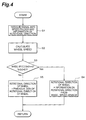
- Fig. 4 is a flowchart for explaining the operation of the signal input section 10a in the ECU 10.
- the signal outputted from the magnetic sensor unit 20b is first resolved into speed pulses and information concerning the rotational direction (step S1). Then the resolved speed pulses are adequately processed and converted from analog data to digital data to compute information associated with the rotational speed of the wheel 12 (wheel speed data) (step S2). If on this occasion the speed at the periphery of the wheel 12 is not more than about 3 km/h, the wheel 12 is assumed to be substantially at a standstill and the wheel speed data is set to zero. This wheel speed data itself can be a result of computation in the ABS computer 10b.
- step S3 It is then determined whether the wheel 12 is in a halt, based on the wheel speed data (step S3).
- the signal input section moves to step S4 to maintain the previously detected information as the information concerning the rotational direction.
- the signal input section goes to step S5 to employ the output signal itself from the magnetic sensor unit 20b, i.e., presently detected information as the information concerning the rotational direction.
- the above processing is also carried out for the other wheels 14, 16, and 18, based on output signals from the rest magnetic sensor units 22b, 24b, and 26b.
- This operation results in obtaining appropriate digital data about the wheel speeds and rotational directions of the respective wheels 12, 14, 16, and 18.
- the switching of direction is restricted with the computation result of wheel speed being zero, whereby it is feasible to prevent occurrence of a malfunction and occurrence of state hunting being repetitive switching of signs, due to an external magnetic field during halts of the wheels.
- Fig. 5 is a drawing for explaining a specific example of the signal processing in the signal input section 10a.
- Fig. 5A indicates a graph showing an actual wheel speed curve. Dotted lines extending horizontally represent threshold values (about 3 km/h) within which the wheel speed is judged as zero.
- Fig. 5B is a graph showing the information about the rotational direction immediately after the resolution at step S1 of Fig. 4.
- Fig. 5C is a graph showing the information about the rotational direction after the correction through steps S4, S5 of Fig. 4.
- Fig. 5D is a graph showing the information about the wheel speed and rotational direction finally outputted from the signal input section 10a.
- the information that the ABS computer 10b and other receive from the signal input section 10a and then process, is digital data.
- the ABS computer 10b operates in either of a normal brake mode, a decompression mode, a retention mode, and a pressure increase mode, based on the information about the wheel speed and rotational direction from the signal input section 10a.
- a normal brake mode the ABS computer 10b supplies no control signal to the actuator 34 and thus a hydraulic pressure equivalent to a stepping-on stroke of the brake pedal 30 is transmitted to each of the wheel cylinders 36, 38, 40, 42 at the respective wheels 12, 14, 16, 18.
- the hydraulic pressure supplied to either of the wheel cylinders 36, 38, 40, 42 corresponding to the slipping wheel is reduced at a fixed rate.
- the hydraulic pressure to either of the wheel cylinders 36, 38, 40, 42 corresponding to the slipping wheel is retained in a decompression state in which the pressure is reduced by a predetermined amount from the pressure equivalent to the stepping-on stroke of the brake pedal 30.
- the hydraulic pressure to the wheel cylinder 36, 38, 40, or 42 for the recovered wheel is maintained in a pressure increased state in which the pressure is increased by a predetermined amount from that in the retention mode according to the stepping-on stroke of the brake pedal 30.
- Safety and speedy braking of the vehicle can be implemented based on the ABS control to switch adequately among the operation modes as described above.
- the TC computer 10c detects slipping of the driving wheels by utilizing the information from the signal input section 10a and information about the engine speed from the unrepresented engine and controls the throttle of the engine and the operation of the actuator 34, thereby effectively preventing the slipping of the driving wheels.
- the VSC computer 10d detects signs of spin and drift during cornering by utilizing the information from the signal input section 10a and from the yaw rate sensor 11 and controls the operation of the actuator 34 and others to maintain the vehicle in a stable state.
- the signal input section 10a accurately detects the wheel speeds and rotational directions of the respective wheels 12, 14, 16, 18, so as to make adequate the ABS control, TC control, and VSC control by the respective computers 10b, 10c, and 10d. Further, since the switching of rotational direction is restricted with the calculation result of the wheel speed of 0, it is feasible to prevent occurrence of a malfunction and occurrence of the state hunting being repetitive switching of signs, due to an external magnetic field during a halt of either of the wheels 12, 14, 16, 18.
- the ECU 10 could perform such processing that the running direction of the vehicle is indistinguishable.
- the switching of the rotational direction is prevented during substantial halts of the wheels, the information about the running direction of the vehicle can be always obtained, so as to optimize the state control of the vehicle.
- the present invention was described above according to the embodiment, but it is noted that the present invention is by no means intended to be limited to the above embodiment.
- the above embodiment was the example wherein the ECU 10 was separated into the signal input section 10a, ABS computer 10b, TC computer 10c, and VSC computer 10d, depending upon the functions, but these arithmetic functions can be also realized by a single computer.
- the restricting means restricts the change of the rotational direction detected by the rotational direction detecting means and thus the correct rotational direction is outputted in the substantially halt state of the wheel, whereby the on-vehicle systems can be made to act accurately.
Landscapes
- Engineering & Computer Science (AREA)
- Physics & Mathematics (AREA)
- General Physics & Mathematics (AREA)
- Transportation (AREA)
- Mechanical Engineering (AREA)
- Regulating Braking Force (AREA)
- Indicating Or Recording The Presence, Absence, Or Direction Of Movement (AREA)
Applications Claiming Priority (2)
| Application Number | Priority Date | Filing Date | Title |
|---|---|---|---|
| JP2000300182A JP2002104149A (ja) | 2000-09-29 | 2000-09-29 | 車輪の回転状態検出装置 |
| JP2000300182 | 2000-09-29 |
Publications (3)
| Publication Number | Publication Date |
|---|---|
| EP1193151A2 true EP1193151A2 (fr) | 2002-04-03 |
| EP1193151A3 EP1193151A3 (fr) | 2002-08-28 |
| EP1193151B1 EP1193151B1 (fr) | 2006-01-04 |
Family
ID=18781898
Family Applications (1)
| Application Number | Title | Priority Date | Filing Date |
|---|---|---|---|
| EP01123483A Expired - Lifetime EP1193151B1 (fr) | 2000-09-29 | 2001-09-28 | Dispositif pour détection de l'état de rotation d'une roue |
Country Status (4)
| Country | Link |
|---|---|
| US (1) | US6747553B2 (fr) |
| EP (1) | EP1193151B1 (fr) |
| JP (1) | JP2002104149A (fr) |
| DE (1) | DE60116424T2 (fr) |
Cited By (5)
| Publication number | Priority date | Publication date | Assignee | Title |
|---|---|---|---|---|
| EP1520760A3 (fr) * | 2003-09-30 | 2006-01-11 | Aisin Seiki Kabushiki Kaisha | Dispositif de détection de rotation |
| WO2006122623A1 (fr) * | 2005-05-20 | 2006-11-23 | Zf Friedrichshafen Ag | Procede pour commander le mode de conduite d'automobiles |
| EP1939633A3 (fr) * | 2006-12-27 | 2010-07-14 | LuK Lamellen und Kupplungsbau Beteiligungs KG | Procédé destiné à la détermination du sens de déplacement d'un véhicule |
| WO2015025227A3 (fr) * | 2013-08-22 | 2015-05-28 | Schrader Electronics Limited | Système et procédé de réalisation de l'auto-localisation d'un capteur de contrôle de pression de pneumatique agencé avec une roue de véhicule utilisant une analyse d'intervalle de confiance et un changement de direction de roue |
| US9333814B2 (en) | 2013-08-22 | 2016-05-10 | Schrader Electronics Ltd. | System and method for performing auto-location of a tire pressure monitoring sensor arranged with a vehicle wheel using confidence interval analysis and rollback events |
Families Citing this family (47)
| Publication number | Priority date | Publication date | Assignee | Title |
|---|---|---|---|---|
| US6834218B2 (en) | 2001-11-05 | 2004-12-21 | Ford Global Technologies, Llc | Roll over stability control for an automotive vehicle |
| US6356188B1 (en) | 2000-09-25 | 2002-03-12 | Ford Global Technologies, Inc. | Wheel lift identification for an automotive vehicle |
| US7233236B2 (en) * | 2000-09-25 | 2007-06-19 | Ford Global Technologies, Llc | Passive wheel lift identification for an automotive vehicle using operating input torque to wheel |
| US7132937B2 (en) | 2000-09-25 | 2006-11-07 | Ford Global Technologies, Llc | Wheel lift identification for an automotive vehicle using passive and active detection |
| US6904350B2 (en) | 2000-09-25 | 2005-06-07 | Ford Global Technologies, Llc | System for dynamically determining the wheel grounding and wheel lifting conditions and their applications in roll stability control |
| US7109856B2 (en) * | 2000-09-25 | 2006-09-19 | Ford Global Technologies, Llc | Wheel lifted and grounded identification for an automotive vehicle |
| JP2002107371A (ja) * | 2000-09-29 | 2002-04-10 | Toyota Motor Corp | 車輪の回転状態検出装置 |
| US6654674B2 (en) | 2001-11-21 | 2003-11-25 | Ford Global Technologies, Llc | Enhanced system for yaw stability control system to include roll stability control function |
| US6556908B1 (en) | 2002-03-04 | 2003-04-29 | Ford Global Technologies, Inc. | Attitude sensing system for an automotive vehicle relative to the road |
| US7079928B2 (en) | 2002-08-01 | 2006-07-18 | Ford Global Technologies, Llc | System and method for determining a wheel departure angle for a rollover control system with respect to road roll rate and loading misalignment |
| US7302331B2 (en) * | 2002-08-01 | 2007-11-27 | Ford Global Technologies, Inc. | Wheel lift identification for an automotive vehicle |
| US7085639B2 (en) * | 2002-08-01 | 2006-08-01 | Ford Global Technologies, Llc | System and method for characterizing the road bank for vehicle roll stability control |
| US7003389B2 (en) | 2002-08-01 | 2006-02-21 | Ford Global Technologies, Llc | System and method for characterizing vehicle body to road angle for vehicle roll stability control |
| US6941205B2 (en) * | 2002-08-01 | 2005-09-06 | Ford Global Technologies, Llc. | System and method for deteching roll rate sensor fault |
| US7194351B2 (en) * | 2002-08-01 | 2007-03-20 | Ford Global Technologies, Llc | System and method for determining a wheel departure angle for a rollover control system |
| US7430468B2 (en) | 2002-08-05 | 2008-09-30 | Ford Global Technologies, Llc | System and method for sensitizing the activation criteria of a rollover control system |
| US20040024505A1 (en) | 2002-08-05 | 2004-02-05 | Salib Albert Chenouda | System and method for operating a rollover control system in a transition to a rollover condition |
| US20040024504A1 (en) * | 2002-08-05 | 2004-02-05 | Salib Albert Chenouda | System and method for operating a rollover control system during an elevated condition |
| US7085642B2 (en) * | 2002-08-05 | 2006-08-01 | Ford Global Technologies, Llc | Method and system for correcting sensor offsets |
| US6961648B2 (en) * | 2002-08-05 | 2005-11-01 | Ford Motor Company | System and method for desensitizing the activation criteria of a rollover control system |
| US6963797B2 (en) * | 2002-08-05 | 2005-11-08 | Ford Global Technologies, Llc | System and method for determining an amount of control for operating a rollover control system |
| GB2397396B (en) * | 2003-01-18 | 2006-05-10 | Luk Lamellen & Kupplungsbau | Automated transmission systems |
| US7239949B2 (en) | 2003-02-26 | 2007-07-03 | Ford Global Technologies, Llc | Integrated sensing system |
| US7653471B2 (en) | 2003-02-26 | 2010-01-26 | Ford Global Technologies, Llc | Active driven wheel lift identification for an automotive vehicle |
| US9162656B2 (en) * | 2003-02-26 | 2015-10-20 | Ford Global Technologies, Llc | Active driven wheel lift identification for an automotive vehicle |
| US7136731B2 (en) * | 2003-06-11 | 2006-11-14 | Ford Global Technologies, Llc | System for determining vehicular relative roll angle during a potential rollover event |
| US7308350B2 (en) * | 2004-05-20 | 2007-12-11 | Ford Global Technologies, Llc | Method and apparatus for determining adaptive brake gain parameters for use in a safety system of an automotive vehicle |
| US7451032B2 (en) * | 2004-06-02 | 2008-11-11 | Ford Global Technologies, Llc | System and method for determining desired yaw rate and lateral velocity for use in a vehicle dynamic control system |
| US7640081B2 (en) | 2004-10-01 | 2009-12-29 | Ford Global Technologies, Llc | Roll stability control using four-wheel drive |
| US7715965B2 (en) | 2004-10-15 | 2010-05-11 | Ford Global Technologies | System and method for qualitatively determining vehicle loading conditions |
| US7668645B2 (en) | 2004-10-15 | 2010-02-23 | Ford Global Technologies | System and method for dynamically determining vehicle loading and vertical loading distance for use in a vehicle dynamic control system |
| US7660654B2 (en) | 2004-12-13 | 2010-02-09 | Ford Global Technologies, Llc | System for dynamically determining vehicle rear/trunk loading for use in a vehicle control system |
| DE102005016110A1 (de) * | 2005-04-08 | 2006-10-12 | GM Global Technology Operations, Inc., Detroit | Verfahren und Vorrichtung zum Ermitteln der Rollrichtung eines Fahrzeugs |
| US7480547B2 (en) | 2005-04-14 | 2009-01-20 | Ford Global Technologies, Llc | Attitude sensing system for an automotive vehicle relative to the road |
| US7590481B2 (en) | 2005-09-19 | 2009-09-15 | Ford Global Technologies, Llc | Integrated vehicle control system using dynamically determined vehicle conditions |
| US8121758B2 (en) | 2005-11-09 | 2012-02-21 | Ford Global Technologies | System for determining torque and tire forces using integrated sensing system |
| US7600826B2 (en) | 2005-11-09 | 2009-10-13 | Ford Global Technologies, Llc | System for dynamically determining axle loadings of a moving vehicle using integrated sensing system and its application in vehicle dynamics controls |
| JP2007170922A (ja) * | 2005-12-20 | 2007-07-05 | Denso Corp | 回転検出装置の信号処理回路 |
| DE102007030431A1 (de) * | 2007-06-29 | 2009-01-02 | Continental Teves Ag & Co. Ohg | Verfahren zur Fahrtrichtungserkennung eines Kraftfahrzeugs |
| JP4997065B2 (ja) * | 2007-10-29 | 2012-08-08 | 日立オートモティブシステムズ株式会社 | 車両制御装置 |
| US20110269595A1 (en) | 2010-04-30 | 2011-11-03 | American Axle & Manufacturing Inc. | Control strategy for operating a locking differential |
| US9076272B2 (en) * | 2013-05-28 | 2015-07-07 | Infineon Technologies Ag | Wheel speed sensor and interface systems and methods |
| DE102013216143B4 (de) * | 2013-08-14 | 2022-12-29 | Zf Friedrichshafen Ag | Verfahren und Steuergerät zur Bildung eines kombinierten Drehzahl-/Drehrichtungssignals |
| US9759737B2 (en) | 2014-08-22 | 2017-09-12 | GM Global Technology Operations LLC | Method and apparatus for monitoring speed and position of a rotating member |
| DE102015113751B4 (de) * | 2014-08-22 | 2021-01-14 | GM Global Technology Operations LLC (n. d. Ges. d. Staates Delaware) | Verfahren zum überwachen der geschwindigkeit und position eines rotierenden elements |
| JP6631453B2 (ja) * | 2016-09-26 | 2020-01-15 | 株式会社アドヴィックス | 車両の制動制御装置 |
| JP7283406B2 (ja) * | 2020-01-31 | 2023-05-30 | トヨタ自動車株式会社 | 車両 |
Family Cites Families (10)
| Publication number | Priority date | Publication date | Assignee | Title |
|---|---|---|---|---|
| US4331917A (en) | 1979-12-13 | 1982-05-25 | Caterpillar Tractor Co. | Speed and direction sensing circuit |
| JPS59224569A (ja) | 1983-06-02 | 1984-12-17 | Mitsubishi Electric Corp | デイジタル速度検出装置 |
| DE3733136A1 (de) | 1987-10-01 | 1989-04-13 | Bosch Gmbh Robert | Elektrische anordnung zur messung der drehgeschwindigkeit |
| US5141071A (en) * | 1990-03-13 | 1992-08-25 | Mazda Motor Corporation | Four-wheel-steered vehicle control system |
| US5473938A (en) * | 1993-08-03 | 1995-12-12 | Mclaughlin Electronics | Method and system for monitoring a parameter of a vehicle tire |
| DE19618867A1 (de) * | 1995-08-26 | 1997-02-27 | Bosch Gmbh Robert | System zur Veränderung eines Drehzahlsignals |
| DE19650935A1 (de) * | 1996-12-07 | 1998-06-10 | Teves Gmbh Alfred | Verfahren und Schaltungsanordnung zur Übertragung von Drehzahlinformationen und Zusatzdaten |
| JP2000187039A (ja) | 1998-12-24 | 2000-07-04 | Honda Motor Co Ltd | 回転検出装置 |
| JP4964358B2 (ja) * | 1999-12-07 | 2012-06-27 | 株式会社デンソー | 回転センサの検出信号処理装置および回転センサの検出信号出力方法 |
| US6498474B1 (en) * | 2001-06-27 | 2002-12-24 | Kelsey-Hayes Company | Rotational velocity and direction sensing system |
-
2000
- 2000-09-29 JP JP2000300182A patent/JP2002104149A/ja active Pending
-
2001
- 2001-09-28 EP EP01123483A patent/EP1193151B1/fr not_active Expired - Lifetime
- 2001-09-28 US US09/964,434 patent/US6747553B2/en not_active Expired - Lifetime
- 2001-09-28 DE DE60116424T patent/DE60116424T2/de not_active Expired - Lifetime
Cited By (8)
| Publication number | Priority date | Publication date | Assignee | Title |
|---|---|---|---|---|
| EP1520760A3 (fr) * | 2003-09-30 | 2006-01-11 | Aisin Seiki Kabushiki Kaisha | Dispositif de détection de rotation |
| WO2006122623A1 (fr) * | 2005-05-20 | 2006-11-23 | Zf Friedrichshafen Ag | Procede pour commander le mode de conduite d'automobiles |
| EP1939633A3 (fr) * | 2006-12-27 | 2010-07-14 | LuK Lamellen und Kupplungsbau Beteiligungs KG | Procédé destiné à la détermination du sens de déplacement d'un véhicule |
| WO2015025227A3 (fr) * | 2013-08-22 | 2015-05-28 | Schrader Electronics Limited | Système et procédé de réalisation de l'auto-localisation d'un capteur de contrôle de pression de pneumatique agencé avec une roue de véhicule utilisant une analyse d'intervalle de confiance et un changement de direction de roue |
| US9278590B2 (en) | 2013-08-22 | 2016-03-08 | Schrader Electronics Ltd. | System and method for performing auto-location of a tire pressure monitoring sensor arranged with a vehicle wheel using confidence interval analysis and change of wheel direction |
| US9333814B2 (en) | 2013-08-22 | 2016-05-10 | Schrader Electronics Ltd. | System and method for performing auto-location of a tire pressure monitoring sensor arranged with a vehicle wheel using confidence interval analysis and rollback events |
| GB2535015A (en) * | 2013-08-22 | 2016-08-10 | Schrader Electronics Ltd | System and method for performing auto-location of a tire pressure monitoring sensor arranged with a vehicle wheel using confidence interval analysis |
| GB2535015B (en) * | 2013-08-22 | 2020-02-26 | Schrader Electronics Ltd | System and method for performing auto-location of a tire pressure monitoring system on a vehicle wheel using change of wheel direction |
Also Published As
| Publication number | Publication date |
|---|---|
| DE60116424D1 (de) | 2006-03-30 |
| US6747553B2 (en) | 2004-06-08 |
| US20020040268A1 (en) | 2002-04-04 |
| EP1193151A3 (fr) | 2002-08-28 |
| JP2002104149A (ja) | 2002-04-10 |
| EP1193151B1 (fr) | 2006-01-04 |
| DE60116424T2 (de) | 2006-09-14 |
Similar Documents
| Publication | Publication Date | Title |
|---|---|---|
| US6747553B2 (en) | Apparatus for detecting rotational state of wheel | |
| EP1193150B1 (fr) | Système et procédé de détection de rotation d'une roue d'un véhicule | |
| US5345385A (en) | Method for detecting driving situation with respect to vehicle yaw behavior | |
| US20090132112A1 (en) | Plausibilization of Sensor Signals in the Event of a Collision | |
| EP3124369A2 (fr) | Dispositif de freinage automatique pour véhicule du type à enfourcher | |
| US5219212A (en) | Anti-skid control system for vehicle | |
| EP3124370A2 (fr) | Dispositif de freinage automatique pour véhicule du type à enfourcher | |
| JP7199929B2 (ja) | 後輪操舵システムの制御方法 | |
| JP3289474B2 (ja) | 車両制御装置 | |
| US6035693A (en) | System for detecting abnormality of yaw rate sensor and lateral acceleration sensor | |
| US20230035844A1 (en) | Electrically propelled two-wheeled vehicle and method for adjusting a drive torque of an electrically propelled two-wheeled vehicle | |
| US20090271073A1 (en) | Stability control system with body-force-disturbance heading correction | |
| GB2368400A (en) | Acceleration sensor fault detector | |
| US6266599B1 (en) | Method and device for adjusting an amount of movement representing the vehicle motion | |
| JPH1081216A (ja) | 制動力配分制御装置 | |
| US6789858B2 (en) | Braking force control system for vehicle | |
| JP2708021B2 (ja) | 車両直進走行状態判定装置 | |
| JP2001525289A (ja) | 自動車の運転状態を制御するための結合システム | |
| KR960003120B1 (ko) | 미끄럼 방지 브레이크 제어 방법 | |
| JP3039071B2 (ja) | 車両旋回限界判定装置 | |
| JP3748595B2 (ja) | 車両のアンチロックブレーキ制御装置 | |
| KR100358738B1 (ko) | 4륜 구동차량 안티록 브레이크 시스템의 차체속도 산출방법 | |
| EP2208651B1 (fr) | Système de stabilité de virage de véhicule commandé par vecteur d'accélération | |
| JP3334943B2 (ja) | 自動変速機の車速センサ故障検知方法 | |
| KR100254224B1 (ko) | 자동차의 정지 제어시 휠 속 검출방법 |
Legal Events
| Date | Code | Title | Description |
|---|---|---|---|
| PUAI | Public reference made under article 153(3) epc to a published international application that has entered the european phase |
Free format text: ORIGINAL CODE: 0009012 |
|
| 17P | Request for examination filed |
Effective date: 20011019 |
|
| AK | Designated contracting states |
Kind code of ref document: A2 Designated state(s): AT BE CH CY DE DK ES FI FR GB GR IE IT LI LU MC NL PT SE TR |
|
| AX | Request for extension of the european patent |
Free format text: AL;LT;LV;MK;RO;SI |
|
| PUAL | Search report despatched |
Free format text: ORIGINAL CODE: 0009013 |
|
| AK | Designated contracting states |
Kind code of ref document: A3 Designated state(s): AT BE CH CY DE DK ES FI FR GB GR IE IT LI LU MC NL PT SE TR |
|
| AX | Request for extension of the european patent |
Free format text: AL;LT;LV;MK;RO;SI |
|
| AKX | Designation fees paid |
Designated state(s): DE FR GB |
|
| 17Q | First examination report despatched |
Effective date: 20030709 |
|
| GRAP | Despatch of communication of intention to grant a patent |
Free format text: ORIGINAL CODE: EPIDOSNIGR1 |
|
| GRAS | Grant fee paid |
Free format text: ORIGINAL CODE: EPIDOSNIGR3 |
|
| GRAA | (expected) grant |
Free format text: ORIGINAL CODE: 0009210 |
|
| AK | Designated contracting states |
Kind code of ref document: B1 Designated state(s): DE FR GB |
|
| REG | Reference to a national code |
Ref country code: GB Ref legal event code: FG4D |
|
| REF | Corresponds to: |
Ref document number: 60116424 Country of ref document: DE Date of ref document: 20060330 Kind code of ref document: P |
|
| ET | Fr: translation filed | ||
| PLBE | No opposition filed within time limit |
Free format text: ORIGINAL CODE: 0009261 |
|
| STAA | Information on the status of an ep patent application or granted ep patent |
Free format text: STATUS: NO OPPOSITION FILED WITHIN TIME LIMIT |
|
| 26N | No opposition filed |
Effective date: 20061005 |
|
| REG | Reference to a national code |
Ref country code: GB Ref legal event code: 732E Free format text: REGISTERED BETWEEN 20090625 AND 20090701 |
|
| REG | Reference to a national code |
Ref country code: GB Ref legal event code: 746 Effective date: 20091103 |
|
| REG | Reference to a national code |
Ref country code: FR Ref legal event code: TQ |
|
| REG | Reference to a national code |
Ref country code: FR Ref legal event code: PLFP Year of fee payment: 15 |
|
| PGFP | Annual fee paid to national office [announced via postgrant information from national office to epo] |
Ref country code: GB Payment date: 20150923 Year of fee payment: 15 |
|
| PGFP | Annual fee paid to national office [announced via postgrant information from national office to epo] |
Ref country code: FR Payment date: 20150811 Year of fee payment: 15 |
|
| GBPC | Gb: european patent ceased through non-payment of renewal fee |
Effective date: 20160928 |
|
| REG | Reference to a national code |
Ref country code: FR Ref legal event code: ST Effective date: 20170531 |
|
| PG25 | Lapsed in a contracting state [announced via postgrant information from national office to epo] |
Ref country code: GB Free format text: LAPSE BECAUSE OF NON-PAYMENT OF DUE FEES Effective date: 20160928 Ref country code: FR Free format text: LAPSE BECAUSE OF NON-PAYMENT OF DUE FEES Effective date: 20160930 |
|
| PGFP | Annual fee paid to national office [announced via postgrant information from national office to epo] |
Ref country code: DE Payment date: 20180918 Year of fee payment: 18 |
|
| REG | Reference to a national code |
Ref country code: DE Ref legal event code: R119 Ref document number: 60116424 Country of ref document: DE |
|
| PG25 | Lapsed in a contracting state [announced via postgrant information from national office to epo] |
Ref country code: DE Free format text: LAPSE BECAUSE OF NON-PAYMENT OF DUE FEES Effective date: 20200401 |