EP1193183A2 - Aufbewahrungsbox für Gegenstände aller Art, insbesondere für Spielkarten - Google Patents
Aufbewahrungsbox für Gegenstände aller Art, insbesondere für Spielkarten Download PDFInfo
- Publication number
- EP1193183A2 EP1193183A2 EP01122910A EP01122910A EP1193183A2 EP 1193183 A2 EP1193183 A2 EP 1193183A2 EP 01122910 A EP01122910 A EP 01122910A EP 01122910 A EP01122910 A EP 01122910A EP 1193183 A2 EP1193183 A2 EP 1193183A2
- Authority
- EP
- European Patent Office
- Prior art keywords
- cover part
- side walls
- recess
- box
- storage box
- Prior art date
- Legal status (The legal status is an assumption and is not a legal conclusion. Google has not performed a legal analysis and makes no representation as to the accuracy of the status listed.)
- Withdrawn
Links
Images






Classifications
-
- A—HUMAN NECESSITIES
- A63—SPORTS; GAMES; AMUSEMENTS
- A63F—CARD, BOARD, OR ROULETTE GAMES; INDOOR GAMES USING SMALL MOVING PLAYING BODIES; VIDEO GAMES; GAMES NOT OTHERWISE PROVIDED FOR
- A63F1/00—Card games
- A63F1/06—Card game appurtenances
-
- A—HUMAN NECESSITIES
- A63—SPORTS; GAMES; AMUSEMENTS
- A63F—CARD, BOARD, OR ROULETTE GAMES; INDOOR GAMES USING SMALL MOVING PLAYING BODIES; VIDEO GAMES; GAMES NOT OTHERWISE PROVIDED FOR
- A63F1/00—Card games
- A63F1/06—Card game appurtenances
- A63F1/062—Boxes or cases for cards
Definitions
- the invention relates to a storage box according to the preamble of claim 1.
- EP-A-0927564 is a storage box for playing cards, namely one So-called Bridge-Bid-Box, known that part of a box-shaped bottom and out there is a box-shaped cover part.
- the lid part of this storage box is on one of its end faces open, causing the cover part to move on the bottom part can be.
- the lid part is in the area of other front side pivotally connected to the bottom part, two of which Side walls of the lid part attached round nipples (called pins there) in two Engage the L-shaped recess made in the side walls of the base part.
- the cover part is opposite the Bottom part shifted by placing the respective nipple horizontally within one Leg of the L-shaped profile is guided. Then the lid part is raised by the respective nipple is guided within the vertical leg of the L-shaped profile becomes.
- a so-called room limiter which is on the inner surface the lid part is arranged, a mechanism is created when closing the box the set of bridge playing cards stuck in it.
- the well-known box does the function described in column 2, lines 3-17 Particularly suitable for use as a bridge bidding box.
- a trapezoidal or truncated pyramid-shaped projection with a complementary one has shaped recess that has extensions that. preferably hemispherical under analog angle design are formed.
- the lead with at least one recess in each the side surfaces and the recesses form together with a spherical Continuation of a snap lock.
- the functionality of the lock caused by the angular shape of the projection and the recess exhibit.
- the object of the invention is therefore to provide a storage box of the type mentioned to create that is equally suitable for storing a wide variety of things is, the cover part is secured against easy opening.
- the storage box according to the invention is characterized in that the Side walls of the cover part each have a square nipple that the side walls of the Bottom part each a recess with a widened section and a tapered Have section into which one of the nipples protrudes, the recess itself extends at least in the direction of the open end face and tapers so far that the angular nipple fits positively in the tapered section of the recess, thereby the cover part is secured against opening in this position.
- the cutouts are not tapered in their Section extend and widen perpendicular to the cover surface of the cover part, whereby the cover part is only pivotable relative to the bottom part when the nipple are located in these widened sections of the recesses.
- the nipples are rectangular and the tapered sections the recesses are slit-shaped. This results in one from nipples and Slits formed precisely fitting lock against opening the lid. Depending on Dimension of the slot can be a more or for the closed state of the box less severe jamming of the nipple can be achieved. This can open the Box can be made more difficult.
- the cutouts are in the area of those ends the side walls of the cover part are arranged, which are not on the open end face of the Cover part, but adjacent to the opposite end, and if the nipple adjacent to this end face of the bottom part at the upper corners there Side walls of the bottom part are arranged. Because this results in moving the Part of the cover already has a large partial opening in the area of the open end face. This can e.g. be useful if small parts such as nails or screws are stored in the box from which only a part (a small number) should be removed. The The lid part then does not need to be opened. The same applies to the Use of the box as a so-called pill box, i.e. as a storage box for Medicines in tablet form.
- the box can also be used to store Compact disks (CDs) or music cassettes (MCs) or the like can be used.
- the bottom part at least in the area the nipple has slits or notches between its side walls and end walls has, whereby to separate the bottom and lid part, the side walls at least in yield resiliently in the upper area facing the cover part.
- the storage box according to the invention can be used for a wide variety of applications be designed by using the bottom part universally with different insert parts Including objects, especially playing cards.
- Base part and the cover part from a plastic, in particular from a Mixed polymer are produced by means of spray printing technology.
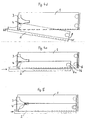
- Figures 1 to 5 show a first in various schematic representations Embodiment in which the cover part has two square nipples which are in recesses protrude from the bottom part.
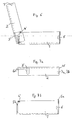
- Figures 6 to 11a-d show a second in different schematic representations Embodiment in which the bottom part has two square nipples that are in recesses of the cover part protrude.
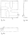
- Figures 12a-b to 14a-c. show further configurations in the form of a bridge board.
- FIG. 1 shows a storage box according to the invention in the transverse view closed state.
- the box which is rectangular in this example and about 15 cm long, 9 cm wide and 4 cm high, consists of a box-shaped bottom part 1 and from a box-shaped cover part 2 which can be folded (put over).
- the bottom part 1 hereinafter also called floor for short, has a recess 3 on each of its side walls a special contour that has a wide area 3a and a narrower tapered area 3b. The contour will be described in detail later.
- the lid part 2 in another also called a lid, has square nipples 4 on its side walls, which are in this example are rectangular and about 8mm long, 4 mm wide and 3 mm are high. Each nipple 4 protrudes towards the inside of the side wall and engages in the corresponding one Recess 3 one.
- the recess 3 has an essentially funnel-shaped Contour starting from one end of the side wall of the bottom 1 towards Tapered the middle of the side wall to a slot about 4 mm wide, so that the rectangular nipple 4 fits straight into the slot.
- This will make the box in the closed state secured against opening: because the contour is in this position the recess is positively adapted to the angular shape of the nipple; the lid 2 can be neither pivoted nor lifted. Only moving the cover part 2 against the bottom part 1 (in the direction of the arrow) is possible, but the nipples 4 from the tapered portions of the recesses. i.e. the slots 3b, are brought out which requires a certain strength.
- the force to be used becomes strength the jamming of the nipple 4 determines and should not be too large.
- One is optimal non-positive jamming, which is only so strong that it is an independent one Moving the cover 2, e.g. when transporting the box, prevented.
- the deadlock against a slight displacement of the lid can also be achieved that the partially overlapping side walls of the lid and base somewhat against each other rub or press lightly against each other.
- FIG. 2 shows the box in the open state, the cover part 2 being approximately vertical to the bottom part 1.
- This condition was first achieved by moving the cover 2 (see arrow direction in FIG. 1) and by subsequently opening the cover 2 (see arrow direction in Fig. 2) reached, the nipple 4 now in the widened Part of the recesses 3 are located.
- the nipple 4 can be within the contour move freely, i.e. the lid 2 can not only be pivoted, but also raised and be lowered again.
- the cover part 2 takes a greater distance from the bottom part 1, whereby the cover 2 is placed vertically on the rear end wall G. can be.
- the upright lid 2 thus forms a kind of privacy screen.
- the box has a snap lock, which also closes guaranteed.
- the snap lock consists of one on the bottom part 1 attached convex elevation 6 and attached to the cover part 2 as a counterpart concave depression 7.
- the elevations and the depressions are spherical segment-shaped designed beads or troughs that interlock very easily.
- Has better interlocking the bottom part 1 in the region of the elevation 6 has a gap 5a which separates the side wall from the Bulkhead separates. This gives the side wall very resilient in this area, what in turn leads to an effective snap lock.
- FIG. 3a shows again the exact design of the lid 2 with its open end face OS and with its opposite end face GS, which is only half-open.
- the two rectangular nipples 4 are located on the inside of the side walls and are arranged opposite each other on the lower edges of the sides.
- the lid 2 In the area of the open end face OS are on the inside of the lid 2 two recesses 7a, which are arranged opposite one another and into which Elevations in the form of correspondingly arranged on the side walls of the base part fit round arches 6 if the lid part on the to close the box Bottom part is pushed.
- the box shown is preferably as Bridge board box is used
- the top surface of the lid 2 is the lid surface diluted (indicated by dashed lines), i.e. the cover 2 has a thin-walled there Area on. The so-called result slips can be kept in this area.
- Fig. 3b shows in detail the counterpart to the lid part described, namely that Bottom part 1.
- This part is also box-shaped, but somewhat smaller, so that Cover part can be put over.
- 3b is the contour of the lateral recess 3 of the bottom part 1 can be seen particularly clearly.
- the recess 3 in the region of the expanded part at the bottom Opening 3c, which serves to close the cover part from the base part 1 without effort separate and reconnect the two. This process will be more precise described with reference to Figures 4a-e. It is then also considered that the Bottom part has two elevations 6 on each side wall.
- FIG. 3b The features which are shown particularly clearly here in FIG. 3b also include Columns 5a and 5b, which are between the side walls and the end walls of the bottom part 1 are located.
- Columns 5a and 5b which are between the side walls and the end walls of the bottom part 1 are located.
- a high elasticity of the side walls is achieved, which is in a expresses resilient tension, this especially in the area of the gap 5a Effect of the snap closure created from recess and elevation 6 supports.
- the gap 5b in the area of the cutout serves primarily to ensure that Squeeze the side walls of the base part 1 and the nipples out of the recesses 3 removed and the lid part can be lifted and removed.
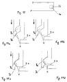
- FIGS. 4a to 4e show the removal of the cover in the sequence of individual steps from the floor, then turning the lid over and reconnecting to the Bottom, so that the lid is finally backwards under the bottom.
- the final state of the arrangement is shown in FIG. 5, which shows the cover part 2 in the rear Location and the bottom part 1 thereon shows.
- This special arrangement of lids and floor is particularly suitable if the box is to be open and freely accessible, the Lid part should not be stored individually and separately from the bottom part.
- the Individual steps to remove and replace the lid are as follows:
- the vertically opened lid part 2 is first opened Moved downward perpendicular to the bottom part 1, the nipple 4 by the special Opening 3c of the recess 3 is passed through (see arrow direction in the direction of Front side GS). As soon as the nipple 4 has left the recess 3, the cover 2 is complete separated from floor 1.
- cover 2 is now turned (see arrow) and then Guided upwards perpendicular to bottom part 1 (see arrow direction upwards).
- the Nipple 4 slides into the special opening 3c of the recess 3.
- the cover part 2 is now connected again to the base part 1, the end face GS now pointing upwards.
- FIG. 4c shows the cover 2 being folded down below the base part 1.
- the Nipple 4 has been pushed so far into the recess 3 that it is in the extended area the recess 3 protrudes and is freely movable.
- the cover part 2 can now be completely below the Bottom part 1 can be pivoted (see arrow direction). Due to the open front side OS cover part 2 and base part 1 can be folded directly together.
- FIG. 4e shows this state, the cover part 2 now being planar on the base part 1 is applied.
- the cover part 2 By moving the cover part 2 in the direction of the tapered area (Slot) of the recess 3, the cover part is completely with the bottom part merged.
- the nipple 4 slides into the slot of the recess 3 and at the same time snap the recess 7a and the elevation 6 into each other, which is an additional Snap lock equals.
- FIG. 5 now shows the state shortly before the closure snaps into place.
- the Nipple 4 is therefore just before the slot stops. It is just a small shift is necessary to completely fix the cover part 2 with to manufacture the bottom part 1. Thanks to this special construction, the lid and bottom are Connected to each other in a very space-saving manner when the box is open. The open one Box can be parked very comfortably without the lid in any way is disturbing.
- the cover wall of the cover part 2 is in the area towards the open end face diluted (wall thinning 8). Now lies the cover part 2 at the bottom of the bottom part 1, so due to the wall thinning 8, a cavity is formed in which flat objects, such as Labeling labels or the like can be kept. If the box e.g. as Playing cards are used, so the cavity is very suitable for storing Result slips.
- the first embodiment described above with reference to FIGS. 1 to 5 stands out particularly characterized in that the bottom part 1 has lateral recesses 3 into which Engage nipples 4, which are located on the side walls of the cover part 2. Doing the recess 3 has a very special contour with an enlarged area and a tapered area, which is preferably designed as a slot.
- FIG. 6 A second designed according to the same construction principle according to the invention Embodiment show Figures 6 to 11a-d.
- This embodiment stands out characterized in that the cover part 2 now has two side walls according to the invention Has recesses 3 'and that the bottom part 1 now has side walls with square nipples 4 'has.
- This second embodiment corresponds accordingly to the first Embodiment inverted design with the same function.
- Figure 6 shows the second embodiment in a state in which the box opened and the lid is opened almost vertically.
- the reference numerals correspond those of the first embodiment, insofar as they are the same reference numerals is.
- the new reference numerals 3 'and 4' refer to a recess 3 ', which is located on the cover part 2 or on a nipple 4 'which is arranged on the bottom part 1 is.
- the cover 2 is also slipped over the bottom part 1 here. Therefore the nipples 4 'protrude, which are arranged on the side walls of the bottom part 1, outwards into the recesses the lid side walls.
- Figures 7a and 7b show the cover part 2 and the bottom part 1 in separate Representations.
- the cover part 2 also has an open end face OS and an opposite half-open end face GS.
- the now on the side walls of the Recesses 3 'to be found in cover part 2 also have a tapered one slit-shaped part and an enlarged part. However, the tapered part is in the Area of the semi-open end face GS; the extended part is towards the middle of the Find sidewall.
- the lid 2 has open at the other end of its side walls Front side OS also depressions 7.
- the nipples 4 ' are now located on the side walls of the base 1, specifically on the upper ones Corners in the area of the semi-open end face GS.
- the nipples 4 'and the recesses 3' are coordinated in terms of their geometry, the slit-shaped part of the Recess 3 adapts to the angular shape of the nipple 4 '.
- the bottom part 1 also has also columns 5a and 5b, which are located between the side walls and the end faces. A spring effect of the side walls is also achieved here.
- FIGS. 8a-d show in detail the partial areas of the cover 2 and the base 1:
- FIG. 8a shows the contour of the recess 3 ' in exact detail in FIG. 8a.
- FIG. 8b shows the side walls of the cover part 2 in a cross section with the recesses 7.
- FIG. 8c shows the details of the base 1 in more detail, in particular the nipple 4 ' and the elevation 6.
- FIG. 8d in turn shows a cross section of the side walls of the Bottom 1 with the concave elevations 6 attached to it.
- both the bottom part 1 and the lid part 2 Made entirely of plastic using injection molding technology.
- Figures 9a-d show the opening of the storage box in a step-wise sequence by moving and then opening the cover part 2.
- FIG a shows the closed state of the box.
- prevent from the recess 7 and Elevation 6 formed snap locks see also Fig. 9b and 9c) an unintentional Move the lid 2.
- FIG. 9c now shows the position of the cover 2, in which the nipple 4 'is already in the extended area of the recess 3 '.
- the lid 2 can now be moved freely be opened.
- Figure 9d the box is shown in the open state, the Lid part 2 is opened up to an approximately vertical position.
- the nipple 4 ' is located now in a corner area of the recess 3 '. This corner area thus forms one Attack.
- a second slit-shaped taper could also be used here be attached to fix the cover 2 in the vertical position.
- FIG. 10 shows a side view of the cover part with the side panels Wells 7a and 7b.
- the main recess 7a is intended when the cover and Bottom part completely absorb the curvature, which is attached to the side of the bottom part.
- This main depression is also called snap-in depression 7a here because it coincides with the curvature forms a snap or snap lock.
- snap-in depression 7a For easier everyone is pushing the lid and base together and for easier snap-in Locking recess 7a upstream of an insertion recess 7b, which is not quite as deep how the locking recess 7a is formed.
- FIGS. 11a to 11d show the function of the snap lock exactly:
- the lid with the depressions 7a and 7b is pushed over the base part, until the curvature 6 is captured by the insertion recess 7b. Then the lid pushed further (in the direction of the arrow), the curvature 6 now coming out of the Insertion recess 7b slides out and the side walls of the lid and bottom be pushed apart, which is a certain elasticity, which further Moving the lid must be overcome. Then the curvature snaps 6 completely into the locking recess 7a, which is equivalent to a snap.
- the Figures 11 a-d show this process very clearly.
- the second exemplary embodiment described with reference to FIGS. 6 to 11a-d also shows the universal use of the storage box according to the invention.
- the box can also be made from a wide variety of materials, such as Plastic, metal, or wood.
- FIG. 12a-b to 14a-c show corresponding configurations of the box as a so-called bridge board with 4 sets of cards each.
- FIG. 12a shows a top view of the insert part E for the board box, wherein insert part E is inserted into the bottom part of the box.
- the special insert here also called insert compartment E, is designed in the form of a bridge board and has four Sub-compartments N, O, S and W for one set of playing cards each.
- the abbreviations "N" to "W” stand for those used in the bridge game and after the four Cardinal directions named "North” to "West”.
- Bridge boards In addition to the special arrangement of the sub - compartments, which form a square shape Bridge boards also has the following characteristic:
- Each sub-compartment is as in the Figure 12b shown, specially designed so that the playing cards kept safe and can still be easily removed.
- the lower compartment has one made of foam formed block on which the cards lie almost in the middle.
- a bridge B presses on the Card set and prevents the cards from falling out of the sub-compartment.
- the cards are usually horizontal in the sub-compartment. Only when you have one behind bridge B. exerts slight pressure on the deck of cards, the deck of cards rises at the other end, i.e. he bounces something out of the compartment so that you can very conveniently complete the deck can remove from the sub-compartment.
- FIGS. 13a to 13c show the bottom part 1 of the bridge board box in different views.
- the aforementioned insert E (see FIGS. 12a / b) is inserted into this base part 1. used.
- the base part 1 has a square basic shape and is basically constructed in this way like the box described above.
- the bottom part and also that in FIGS. 14a-c illustrated lids are of a special design, so that the lid part from Bottom part can be completely separated and pushed under the bottom part can.
- the construction corresponds essentially to that already with reference to FIGS. 4a-e and Fig. 5 described design of the box.
- FIGS. 14a to 14c show different views the cover part 2, which can be folded onto the nipple by means of the nipples which engage in the recesses 3 Bottom part is attached. 14c, the recess 3 is open at one point, so that the nipple can be brought out there and the cover completely from Bottom part can be solved. 14a and b is a thinning of the wall 8 can be seen in the cover part, which is used for storing results slips.
- the cover part has 2 of the box for each sub-compartment N to W a recess or a viewing window in the Cover surface. Below that is the lid thinner 8 for storing the Result slip.
- the information such as "N” to "W”, the number "1” and the divider can be read immediately.
Landscapes
- Engineering & Computer Science (AREA)
- Multimedia (AREA)
- Closures For Containers (AREA)
- Packaging Of Annular Or Rod-Shaped Articles, Wearing Apparel, Cassettes, Or The Like (AREA)
- Packaging For Recording Disks (AREA)
- Details Of Rigid Or Semi-Rigid Containers (AREA)
Abstract
Description
Claims (12)
- Aufbewahrungsbox mit einem kastenförmigen Bodenteil (1) und mit einem darüber klappbaren kastenförmigen Deckelteil (2), das eine offene Stirnseite (OS) hat, wobei zum Aufklappen des Deckelteils (2) das Deckelteil (2) im Bereich der anderen Stirnseite (GS) mittels Nippeln schwenkbar mit dem Bodenteil (1) verbunden ist,
dadurch gekennzeichnet, dass die Seitenwände des Deckelteils (2) je einen eckigen Nippel (4) aufweisen,
dass die Seitenwände des Bodenteils (1) je eine Aussparung (3) mit einem aufgeweiteten Abschnitt (3a) und einem verjüngten Abschnitt (3b) aufweisen, in die jeweils einer der Nippel (4) hineinragt, wobei die Aussparung (3) sich zumindest in Richtung zu der offenen Stirnseite (O) hin erstreckt und soweit verjüngt, dass der eckige Nippel (4) formschlüssig in den verjüngten Abschnitt der Aussparung (3) passt, wodurch das Deckelteil (2) in dieser Position gegen das Aufklappen gesichert ist. - Aufbewahrungsbox nach Anspruch 1, dadurch gekennzeichnet, dass
die Aussparungen (3) in ihren aufgeweiteten Abschnitten (3a) sich senkrecht zur Bodenfläche des Bodenteils (1) erstrecken und aufweiten, wodurch das Deckelteil (2) nur dann relativ zum Bodenteil (1) schwenkbar ist, wenn die Nippel (4) sich in diesen aufgeweiteten Abschnitten (3a) der Aussparungen (3) befinden. - Aufbewahrungsbox nach Anspruch 1 oder 2, dadurch gekennzeichnet, dass
die Nippel (4) rechteckig ausgebildet sind und das die verjüngten Abschnitte (3b) der Aussparungen (3) schlitzförmig ausgebildet sind. - Aufbewahrungsbox nach einem der vorhergehenden Ansprüche, dadurch gekennzeichnet, dass die Aussparungen (3) im Bereich derjenigen Enden der Seitenwände des Bodenteils (1) angeordnet sind, die an die der offenen Stirnseite (OS) gegenüberliegenden Stirnseite (GS) des Deckelteils (2) angrenzen, und dass die Nippel (4) im entsprechenden Bereich der Seitenwände des Deckelteils (2) angeordnet sind.
- Aufbewahrungsbox nach einem der vorhergehenden Ansprüche, dadurch gekennzeichnet, dass die Seitenwände des Bodenteils (1) mindestens eine Erhebung, insbesondere eine konvexe Erhebung (6), aufweisen, und dass die Seitenwände des Deckelteils (2) je eine Vertiefung, insbesondere eine konkave Vertiefung (7a) mit einer Einführungsvertiefüng (7b), aufweisen, in die die jeweilige Erhebung (6) beim Schließen der Aufbewahrungsbox, insbesondere beim Zuschieben des Deckelteils (2), einschnappt.
- Aufbewahrungsbox nach Anspruch 5, dadurch gekennzeichnet,
die Vertiefungen, insbesondere die konkaven Vertiefungen (7a) mit den Einführungsvertiefungen (7b), an denjenigen Enden der Seitenwände des Deckelteils (2) angeordnet sind, die an die offene Stirnseite (OS) des Deckelteils (2) angrenzen, und
dass die Erhebungen (6) angrenzend an die entsprechenden Enden der Seitenwände des Bodenteils (1) angeordnet sind. - Aufbewahrungsbox nach Anspruch 6, dadurch gekennzeichnet, dass
das Bodenteil (1) zumindest im Bereich der Erhebungen (6) zwischen seinen Seitenwänden und Stirnwänden je einen Schlitz (5a) oder eine Einkerbung aufweist, wodurch zum Einschnappen der Erhebungen (6) in die Vertiefungen (7a) über die Einführungsvertiefungen (7b) die Seitenwände zumindest im oberen dem Deckelteil (2) zugewandten Bereich federnd nachgeben. - Aufbewahrungsbox nach einem der vorhergehenden Ansprüche, dadurch gekennzeichnet, dass das Bodenteil (1) zumindest im Bereich der Aussparungen (3) zwischen seinen Seitenwänden und Stirnwänden je einen Schlitz (5b) oder eine Einkerbung aufweist, wodurch zum Trennen von Boden- und Deckelteil die Seitenwände zumindest im oberen dem Deckelteil (2) zugewandten Bereich federnd nachgeben.
- Aufbewahrungsbox nach einem der vorhergehenden Ansprüche, dadurch gekennzeichnet, dass das Bodenteil (1) universell mit verschiedenen Einsatzfächern (E) oder Einsatzteilen zur Aufnahme von Gegenständen, insbesondere von Spielkarten, bestückbar ist.
- Aufbewahrungsbox nach Anspruch 9, dadurch gekennzeichnet, dass das Bodenteil (1) mit einem Einsatzfach (E) für Bridge-Spielkarten bestückt ist mit vier Unterfächer (N, O, S, W), die in Form eines Bridge-Boards angeordnet sind, und
dass die Deckelfläche des Deckelteils (2) im Bereich eines jeden Unterfaches jeweils eine Aussparung aufweist, durch die Bezeichnungsbereiche sichtbar sind. - Aufbewahrungsbox nach einem der vorhergehenden Ansprüche, dadurch gekennzeichnet, dass das Bodenteil (1) sowie das Deckelteil (2) aus einem Kunststoff, insbesondere aus einem Mischpolymerisat, mittels Spritzdrucktechnik gefertigt sind.
- Aufbewahrungsbox mit einem kastenförmigen Bodenteil (1) und mit einem darüber klappbaren kastenförmigen Deckelteil (2), das eine offene Stirnseite (OS) hat, wobei zum Aufklappen des Deckelteils (2) das Deckelteil (2) im Bereich der anderen Stirnseite (GS) mittels Nippeln schwenkbar mit dem Bodenteil (1) verbunden ist,
dadurch gekennzeichnet, dass die Seitenwände des Bodenteils (1) je einen eckigen Nippel (4') aufweisen,
dass die Seitenwände des Deckelteils (1) je eine Aussparung (3') mit einem aufgeweitetem Abschnitt und einem verjüngten Abschnitt aufweisen, in die jeweils einer der Nippel (4') hineinragt, wobei die Aussparung (3) sich zumindest in Richtung zu der anderen Stirnseite (GS) hin erstreckt und soweit verjüngt, dass der eckige Nippel (4') formschlüssig in den verjüngten Abschnitt der Aussparung (3) passt, wodurch das Deckelteil (2) in dieser Position gegen das Aufklappen gesichert ist.
Applications Claiming Priority (2)
| Application Number | Priority Date | Filing Date | Title |
|---|---|---|---|
| DE2000147987 DE10047987C1 (de) | 2000-09-28 | 2000-09-28 | Aufbewahrungsbox für Gegenstände aller Art, insbesondere für Spielkarten |
| DE10047987 | 2000-09-28 |
Publications (2)
| Publication Number | Publication Date |
|---|---|
| EP1193183A2 true EP1193183A2 (de) | 2002-04-03 |
| EP1193183A3 EP1193183A3 (de) | 2004-01-07 |
Family
ID=7657905
Family Applications (1)
| Application Number | Title | Priority Date | Filing Date |
|---|---|---|---|
| EP01122910A Withdrawn EP1193183A3 (de) | 2000-09-28 | 2001-09-25 | Aufbewahrungsbox für Gegenstände aller Art, insbesondere für Spielkarten |
Country Status (2)
| Country | Link |
|---|---|
| EP (1) | EP1193183A3 (de) |
| DE (1) | DE10047987C1 (de) |
Families Citing this family (2)
| Publication number | Priority date | Publication date | Assignee | Title |
|---|---|---|---|---|
| FR3053599A1 (fr) * | 2016-07-11 | 2018-01-12 | Christian Jean Felix Antoine Lafon | Dispositif permettant de retenir les cartons d'encheres, utilises pour jouer au bridge, dans la boite a encheres si l'on tombe cette boite |
| EP4201493B1 (de) * | 2021-12-27 | 2025-04-30 | Cartamundi Services NV | Spielkartenmanipulationsvorrichtung |
Citations (2)
| Publication number | Priority date | Publication date | Assignee | Title |
|---|---|---|---|---|
| DE19528771A1 (de) | 1995-08-04 | 1997-02-06 | Robert Pappler | Behältnis, insbesondere für Speisen |
| EP0927564A2 (de) | 1997-12-31 | 1999-07-07 | Helmut Gschweng | Bridge - Bid - Box |
-
2000
- 2000-09-28 DE DE2000147987 patent/DE10047987C1/de not_active Expired - Fee Related
-
2001
- 2001-09-25 EP EP01122910A patent/EP1193183A3/de not_active Withdrawn
Patent Citations (2)
| Publication number | Priority date | Publication date | Assignee | Title |
|---|---|---|---|---|
| DE19528771A1 (de) | 1995-08-04 | 1997-02-06 | Robert Pappler | Behältnis, insbesondere für Speisen |
| EP0927564A2 (de) | 1997-12-31 | 1999-07-07 | Helmut Gschweng | Bridge - Bid - Box |
Also Published As
| Publication number | Publication date |
|---|---|
| EP1193183A3 (de) | 2004-01-07 |
| DE10047987C1 (de) | 2002-01-24 |
Similar Documents
| Publication | Publication Date | Title |
|---|---|---|
| DE3883396T2 (de) | Abschliessbare dose. | |
| DE3236643A1 (de) | Behaelter zur aufbewahrung eines bilderstapels | |
| DE3704393C1 (de) | Faltkarte | |
| EP2147867B1 (de) | Aufbewahrungskasten | |
| DE3236644A1 (de) | Behaelter fuer einen bilderstapel | |
| AT400703B (de) | Transport- und lagerbehälter | |
| DE10047987C1 (de) | Aufbewahrungsbox für Gegenstände aller Art, insbesondere für Spielkarten | |
| DE2921440A1 (de) | Klappbarer behaelter | |
| DE2525169B2 (de) | Kunststoff-flaschenkasten mit verriegelungsvorrichtung | |
| EP2631189B1 (de) | Faltschachtel | |
| DE102018203565B4 (de) | Pappregal | |
| DE69601027T2 (de) | Verpackungsschachtel mit sicherheitsverschluss | |
| DE10237138A1 (de) | Absteller für ein Kältegerät | |
| DE20016736U1 (de) | Aufbewahrungsbox für Gegenstände aller Art, insbesondere für Spielkarten | |
| DE9306650U1 (de) | Kassette zur Aufbewahrung mehrerer plattenförmiger Datenträger o.dgl. | |
| DE2719672C3 (de) | Wahlurne | |
| DE2835165C2 (de) | Behälter zum Aufbewahren von fotografischen Bildern | |
| EP0786413A1 (de) | Behälter | |
| WO2024094783A1 (de) | Behälter und set zur herstellung eines behälters | |
| DE2218762C3 (de) | Erweiterbares Gestell | |
| DE202020106914U1 (de) | Transport- und Lagerbehälter mit verschwenkbaren Seitenwänden | |
| DE8909343U1 (de) | Schutzkörper für Verpackungen von Gegenständen, die zu schützende, konvexe Teile aufweisen | |
| DE102013110764A1 (de) | Kartonzuschnitt | |
| DE202006019345U1 (de) | Verpackungsanordnung | |
| DE7018704U (de) | Tragebehaelter. |
Legal Events
| Date | Code | Title | Description |
|---|---|---|---|
| PUAI | Public reference made under article 153(3) epc to a published international application that has entered the european phase |
Free format text: ORIGINAL CODE: 0009012 |
|
| AK | Designated contracting states |
Kind code of ref document: A2 Designated state(s): AT BE CH CY DE DK ES FI FR GB GR IE IT LI LU MC NL PT SE TR |
|
| AX | Request for extension of the european patent |
Free format text: AL;LT;LV;MK;RO;SI |
|
| PUAL | Search report despatched |
Free format text: ORIGINAL CODE: 0009013 |
|
| AK | Designated contracting states |
Kind code of ref document: A3 Designated state(s): AT BE CH CY DE DK ES FI FR GB GR IE IT LI LU MC NL PT SE TR |
|
| AX | Request for extension of the european patent |
Extension state: AL LT LV MK RO SI |
|
| 17P | Request for examination filed |
Effective date: 20040705 |
|
| AKX | Designation fees paid |
Designated state(s): AT BE CH CY DE DK ES FI FR GB GR IE IT LI LU MC NL PT SE TR |
|
| GRAP | Despatch of communication of intention to grant a patent |
Free format text: ORIGINAL CODE: EPIDOSNIGR1 |
|
| STAA | Information on the status of an ep patent application or granted ep patent |
Free format text: STATUS: THE APPLICATION IS DEEMED TO BE WITHDRAWN |
|
| 18D | Application deemed to be withdrawn |
Effective date: 20050401 |