EP1193201A1 - Méthode et dispositif pour former une formation imbriquée double de produits imprimés - Google Patents
Méthode et dispositif pour former une formation imbriquée double de produits imprimés Download PDFInfo
- Publication number
- EP1193201A1 EP1193201A1 EP01120926A EP01120926A EP1193201A1 EP 1193201 A1 EP1193201 A1 EP 1193201A1 EP 01120926 A EP01120926 A EP 01120926A EP 01120926 A EP01120926 A EP 01120926A EP 1193201 A1 EP1193201 A1 EP 1193201A1
- Authority
- EP
- European Patent Office
- Prior art keywords
- conveyor
- printed products
- transfer
- conveying
- printed
- Prior art date
- Legal status (The legal status is an assumption and is not a legal conclusion. Google has not performed a legal analysis and makes no representation as to the accuracy of the status listed.)
- Granted
Links
- 238000000034 method Methods 0.000 title claims abstract description 27
- 230000015572 biosynthetic process Effects 0.000 title claims description 40
- 238000011144 upstream manufacturing Methods 0.000 claims description 5
- 230000003213 activating effect Effects 0.000 claims description 3
- 238000005755 formation reaction Methods 0.000 description 33
- 239000000543 intermediate Substances 0.000 description 28
- 210000000056 organ Anatomy 0.000 description 4
- 230000032258 transport Effects 0.000 description 4
- 238000011161 development Methods 0.000 description 2
- 230000018109 developmental process Effects 0.000 description 2
- 230000001419 dependent effect Effects 0.000 description 1
- 238000004519 manufacturing process Methods 0.000 description 1
- 230000002093 peripheral effect Effects 0.000 description 1
Images

Classifications
-
- B—PERFORMING OPERATIONS; TRANSPORTING
- B65—CONVEYING; PACKING; STORING; HANDLING THIN OR FILAMENTARY MATERIAL
- B65H—HANDLING THIN OR FILAMENTARY MATERIAL, e.g. SHEETS, WEBS, CABLES
- B65H29/00—Delivering or advancing articles from machines; Advancing articles to or into piles
- B65H29/66—Advancing articles in overlapping streams
- B65H29/6609—Advancing articles in overlapping streams forming an overlapping stream
-
- B—PERFORMING OPERATIONS; TRANSPORTING
- B65—CONVEYING; PACKING; STORING; HANDLING THIN OR FILAMENTARY MATERIAL
- B65H—HANDLING THIN OR FILAMENTARY MATERIAL, e.g. SHEETS, WEBS, CABLES
- B65H2301/00—Handling processes for sheets or webs
- B65H2301/40—Type of handling process
- B65H2301/44—Moving, forwarding, guiding material
- B65H2301/444—Stream of articles in shingled formation, overlapping stream
- B65H2301/4447—Stream of articles in shingled formation, overlapping stream multiple streams
- B65H2301/44472—Stream of articles in shingled formation, overlapping stream multiple streams superposed
-
- B—PERFORMING OPERATIONS; TRANSPORTING
- B65—CONVEYING; PACKING; STORING; HANDLING THIN OR FILAMENTARY MATERIAL
- B65H—HANDLING THIN OR FILAMENTARY MATERIAL, e.g. SHEETS, WEBS, CABLES
- B65H2301/00—Handling processes for sheets or webs
- B65H2301/40—Type of handling process
- B65H2301/44—Moving, forwarding, guiding material
- B65H2301/447—Moving, forwarding, guiding material transferring material between transport devices
- B65H2301/4471—Grippers, e.g. moved in paths enclosing an area
-
- B—PERFORMING OPERATIONS; TRANSPORTING
- B65—CONVEYING; PACKING; STORING; HANDLING THIN OR FILAMENTARY MATERIAL
- B65H—HANDLING THIN OR FILAMENTARY MATERIAL, e.g. SHEETS, WEBS, CABLES
- B65H2301/00—Handling processes for sheets or webs
- B65H2301/40—Type of handling process
- B65H2301/44—Moving, forwarding, guiding material
- B65H2301/447—Moving, forwarding, guiding material transferring material between transport devices
- B65H2301/4473—Belts, endless moving elements on which the material is in surface contact
- B65H2301/44732—Belts, endless moving elements on which the material is in surface contact transporting articles in overlapping stream
Definitions
- the invention relates to a method for forming a Scale flow from first and second printed products, in each of which a first and a second printed product are largely congruent with each other (Double scale formation) according to claim 1 and one Device for performing the method according to claim 8.
- the invention further relates to an apparatus for forming and conveying a shingled stream away from printed products at either a first transfer area or one downstream of the first transfer area lying second transfer area
- Printed products e.g. Newspapers, magazines, Magazines, leaflets, and the like are used during the Often manufactured in a so-called scale arrangement transported from one processing station to the next.
- a printed product overlaps a scale arrangement underlying, further forward in the conveying direction located printing product partially, the in Direction of conveyance lateral edges of the printed products in the close essentially flush with each other.
- at folded printed products can be distinguished Forward shingled arrangement with the folded edge of each printed product in the conveying direction at the front is from a backward scale arrangement in which the Fold lies at the back in the conveying direction.
- the fold edge can lie above or below.
- Scale arrangements will be for example, formed by printing products from a Processing drum or from a stack of printed products seized individually and in regular time Clearances placed on a conveyor belt of a conveyor be that continuously with a predetermined Speed moves. Grasping individuals Printing products made from a processing drum come, by arranged at regular intervals The gripper of an intermediate conveyor is, for example, in the EP-A 0 686 463 or EP-A 0 753 386.
- the invention has for its object a method and a device for forming a shingled stream Specify groups of printed products.
- a method and a device for forming a Double scale flow in which such a group two Printed products includes to be specified.
- the invention is also based on the object known device for forming a stream of shingles further develop that greater flexibility regarding the direction of transport and the type of removed scale formation is accessible.
- the task is solved by a method of education a shingled stream of first and second Printing products in a double scale formation with the features of claim 1.
- the task continues solved by a device for performing the Method with the features of claim 8. Die Flexibility of transport devices is increased with a device with the features of claim 18.
- first and second printed products alternately seized individually by an intermediate conveyor and placed on a conveyor belt of a conveyor, wherein a second printed product to the conveyor that it is largely congruent, i.e. with maximum overlap, on a first, already on the Removed conveyor and the previous print product scale-like overlapping printed product comes to lie.
- the "first" print product is in The following is the first printed product to be stored referred to that in a group of printed products is at the bottom.
- the "second" printed product is that designated that with maximum overlap on the first Printed product rests.
- First and second print products can, but need not, be different. For example, they are different when different Intermediates for the production of a main product grouped should be, and immediately, if only further processing of stacks.
- a gripper conveyor is preferably used as the intermediate conveyor with one behind the other in the conveying direction Grippers for use.
- the "first" grippers are Gripper, which is a first printed product capture as a “second” gripper such for inclusion of a second printed product.
- First and second grippers can be structurally identical. Change according to the invention first gripper with the first grasped by it Printed products with second grippers with them captured second printing products. Should one Scale formation with more than two printed products per Group are formed, so will still be “third", “fourth” etc. printing products on the first and second printed product.
- the first and second printed products which come, for example, from a processing drum or from a stack of printed products, are individually and successively captured by the intermediate conveyor, which conveys at a conveying speed v 1 .
- a stream of printed products is formed which have approximately the same conveyor distance d from one another.
- the grippers of the intermediate conveyor preferably run along a closed orbit.
- a first printed product is fed to a conveyor belt of a conveyor, which conveys at a conveying speed v 2 , for example, while opening the assigned first gripper.
- a second printed product is fed to the conveyor belt in such a way that it is congruent on an already stored first printed product.
- first or second printed products are released either at two transfer points spaced apart in the conveying direction.
- the distance D
- the transfer points are adapted to the conveying speeds v 1 , v 2 of the intermediate and away conveyors, the conveying distance d in the transfer area and the conveying directions relative to one another.
- x 1 , x 2 are the x coordinates of the first or second transfer point, the orientation of the conveyor determining the x axis.
- Approximately D (v 1 -v 2 ) v 2 d preferably applies, where v 1 and v 2 have the same sign for the same conveying directions.
- v 1 is the speed component in the conveying direction of the conveyor.
- the device according to the invention contains at least one Intermediate conveyor with moving along an orbit Grippers for gripping printed products and for Conveying the printed products to a transfer area, one designed as a belt conveyor with a conveyor belt Conveyor to take over the print products in the Transfer area and for conveying away the printed products, e.g. to another processing station.
- the inventive The device further contains at least a trigger device for triggering two each successive grippers of the intermediate conveyor in the Transfer area, triggering on the same Transfer point one after the other or to spaced transfer points.
- the advantage of the invention is that simple Converting known transport devices to a double or Multiple scale arrangement can be achieved. This will further process the products Simplified because the print products are not additional can be grouped using independent devices have to.
- the printed products are viewed from above on the conveyor belt of the conveyor or on those already deposited on it Printed products filed, with the conveying directions are either the same or opposite to each other.
- this variant can be done by swiveling the gripper such that the gripped edge in the conveying direction of the Conveyor shows a forward shed arrangement are formed in which the folds or the gripped Edges, lie at the front in the conveying direction.
- the forward double scale arrangement is preferably used Process variant with two transfer points.
- a conveying device has a device for carrying it out of the method preferably two away conveyors.
- By targeted control of the gripper or triggering elements of the Intermediate conveyors can selectively print products hand over the first or the second conveyor become.
- the upstream conveyor can to be movable to the further conveyance of Printing products to the further conveyor facilitate.
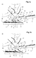
- FIG. 1a, b show an inventive device for Formation of a double scale formation in two snapshots, and that at the same time dropping one first and second printed products 4 and 5 (Fig. 1a), and half a period T later (Fig. 1b), where T the time between dropping two first or two second printed products 4, 5 indicates.
- the device according to the invention comprises an intermediate conveyor 1 with a plurality of rotating on one Drum 21 grippers 6 arranged along its circumference, 7.
- the grippers 6, 7 are arranged by stationary in the room Release elements 8, 9, 10, 16 opened or closed, when the gripper rotates on the drum 21 corresponding trigger organ passes.
- the trigger organs are, for example, suitably trained sets.
- Release member 10 With a first arranged at a receiving point 22 Release member 10 are passing grippers 7, 6 closed and so grab from a processing drum 12 upcoming printing products 4, 5.
- the first triggering element 10 can always be active to everyone at the reception point 22 to close past grippers 6, 7.
- the Printed products 4, 5 are now by means of the grippers 6, 7 circumferentially along a through the shape of the drum 21 predetermined approximately circular movement path U to a transfer area 15 in the lower part of the drum 21 promoted.
- the orientation of the printed products in the room can be changed by swiveling the grippers, e.g. also by means of suitable backdrops.
- In the transfer area 15 there is a first one below the drum 21
- the from Intermediate conveyor 1 funded first and second Printed products 4 and 5 filed.
- first release trigger element 8 For storing a first printed product 4 each on the conveyor belt or partially on the previous stack 24 a first release trigger element 8 is present, the temporary one Gripper 6, the first printed products 4 included ("first" gripper) at a first transfer point 13 releases by opening.
- the first transfer point 13 is at the lowest point of the orbit U.
- Das first release trigger 8 is controlled so that it only every second passing gripper 6, 7 opens, i.e. opens all first grippers 6 and all second Gripper 7 can be closed. This can be done by for example pneumatically or electrically controlled Movement of the corresponding opening backdrop into or can be realized from the trajectory. With that be on the first transfer point 13 only the first printed products 4 stored. All second print products 5 are moved on to a second transfer point 14 a second release trigger element 9 is arranged.
- the second release trigger member 9 can also be permanently active when only stack 24 is out two printed products are to be formed.
- the first Dispensing release element 8 is driven in a clocked manner so that only every second passing gripper opens.
- the release trigger elements 8, 9 can also be used can be controlled at the same time, so as to print products 4, 5 to release simultaneously. The next release then takes place two bars later.
- the conveying speed v 1 at which the grippers 6, 7 of the intermediate conveyor 1 rotate, the conveying speed v 2 of the conveyor belt 17 of the conveyor 2 and the distance between the first and second transfer points 13, 14 are matched to one another such that a second printed product 5 is possible as far as possible is placed exactly on a first, already stored printed product. It is particularly simple if the conveyor belt 17 moves at half the conveying speed of the intermediate conveyor.
- the transfer points 13, 14 are preferably at a distance D which corresponds approximately to the conveying distance d.
- the device shown in FIGS. 1a, 1b has one second conveyor 3 to form a backward scale formation on, in which the free end 26 one Printed product in the direction of conveyance of the second conveyor 3 and the end 27 gripped by the grippers 6, 7 is directed opposite.
- the second conveyor 3 is in the plane of the orbit U des Intermediate conveyor 1 laterally from the intermediate conveyor 1. He is in a position from the position shown movable in the in a further transfer area 16 a third transfer point 23 printed products 4, 5 the conveyor belt 20 of the conveyor 3 are placed can.
- the intermediate conveyor 1 has a third Dispensing trigger 18 on the middle of the Wheel 21 is arranged. Should print products 4, 5 the second conveyor 3 are handed over, that is third release trigger member 18 constantly activated.
- the additional conveyor 11 has at least one with twice the conveying speed like that Conveyor 3 revolving Aufschiebocken 19 on the takes every second incoming print product with it and picks it up postpones the previous first product.
- Such a Away conveyors are shown in more detail in FIGS. 2a, b and described.
- the conveyor 3 and the third release trigger 18 can also be in the upper area of the drum 21 may be arranged, the conveyor belt 20, as in the Fig. 2a, b shown, tangential to the trajectory of the Gripper 6, 7 runs.
- a conveyor can be used an additional conveyor 11 also in the lower area, i.e. be arranged below the intermediate conveyor 1.
- the conveyor 2 with a Additional conveyor to be equipped in the same First and second time intervals Pushes printed products in pairs on each other.
- a second release trigger element 9 to be dispensed with is dispensed with.
- Additional conveyor 11 can be dispensed with entirely. This is for example, the case when the device only for Switching between different conveying directions or Paths or to switch from forward to Backward scale formation is used.
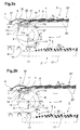
- FIGS. 2a, b show another device according to the invention with an intermediate conveyor 1 ', a first conveyor 2' (shown in dashed lines) and a further conveyor 3 '.
- the grippers 6 ', 7' run along a partially circular orbit U '.
- all the grippers 6', 7 ' are opened by a delivery trigger element 18' as they pass.
- the printed products 4, 5 are placed on a conveyor belt 20 'of the conveyor 3' which is tangential to the orbit in the transfer area 16 '. Every second printed product 5 is pushed with an additional conveyor 11 'onto the first printed product 4 placed in front of it.
- the additional conveyor 11 ' has a peripheral push-on cam 19' which projects into the plane of the conveyor belt 20 'and moves at twice the speed of the conveyor belt 20'.
- the additional conveyor 11 ' is arranged on the side of the conveyor belt 20'.
- the push-on cam 19 ' is fastened to a conveyor element, for example a belt 11a, which runs around two rollers 11b, 11c.
- a rearward double-scale formation 25' is formed, in which the gripped ends 27 of the printed products point against the direction of movement of the removal conveyor.
- the conveying speed v 2 of the conveyor 3 ' is approximately half the conveying speed v 1 of the intermediate conveyor 1' in the transfer area 16 '.
- the speed of the push-on cam 19 ' corresponds to the conveying speed v 1 .
- a further conveyor 2' is provided, which is shown in broken lines.
- the second release trigger element 9 ' is controlled in such a way that it only opens second grippers 7' which pass the second transfer point 14 '.
- the first discharge trigger element 8 ' which is arranged in the direction of rotation before the second discharge trigger element 9', preferably opens all the grippers and therefore leads to the discharge of first printed products 4 at the first transfer point 13 '.
- the conveyor belt 17 'of the conveyor 2' transports against the conveying direction of the intermediate conveyor.
- a second printed product 5 released at the second transfer point 14 ′ is thus placed on the first printed product 4 that has already been deposited.
- the conveying speeds v 1 , v 2 'and the distance D between the delivery release elements 8', 9 ' are matched to one another in such a way that two products are placed onto one another as precisely as possible.
- the conveying speed of the conveyor v 2 is half the conveying speed v 1 of the intermediate conveyor 1 ', and the distance between the first and second transfer points 13', 14 'is d / 2.
- first and second trigger elements are then corresponding to be arranged so that first and second printed products come to lie directly on top of each other.
- Trigger organs are, for example, opening scenes that in the trajectory of the gripper can be introduced and with Corresponding elements of the grippers work together to achieve the Open or close the gripper. Should from one continuous sequence of printed products just every second are released, the one that forms the triggering element Opening setting in the control unit Periodically introduced into the movement path or removed from it.
- FIG. 3a, b is the arrangement of Fig. 1a, b at Switch between a first one leading to the left Conveyor 2 and a second one leading to the right Conveyor 3 shown.
- the elements shown in the Device correspond to those of Fig. 1a, b and are with provided the same reference numerals.
- the lower conveyor 2 is operated when the third release trigger member 18 deactivated and one or both of the further release trigger organs 8, 9 are activated.
- the first and that second release trigger member 8, 9 are on top of each other matched activated or deactivated if a double scale should be formed, as shown in Fig. 1a, b. It is for the formation of a single flake as in Fig. 3a sufficient if one of the two delivery release elements 8, 9 is constantly active.
- the first Dispensing trigger 8 inactive, so that the printed products only released at the second transfer point 14 become. It can easily be on a double scale formation can be switched by the first release trigger 8 switched on at defined time intervals is using a second printed product at the same time a first printed product in the second transfer point 14 to release.
- the second conveyor 3 is located 3a in a rest position in which it is the Movement of the printed products 4, 5 in the intermediate conveyor 1 not disabled.
- the second conveyor 3 is active and at the Intermediate conveyor 1 moved up.
- the constantly active third delivery release member 18 becomes each gripper 6, 7, which passes the assigned transfer area 23 opened and places a printed product 4, 5 on the Conveyor 3 from.
- a single scale is formed by the additional conveyor 11 is inactive, as shown here. If you want to switch to a double scale formation, the additional conveyor 11 is activated and thus pushes two printed products 4, 5 on top of each other. Should basically no double scale can be formed the intermediate conveyor can also be dispensed with.
- FIG. 4a, b show the switching between the Conveying away with a first conveyor 2 'and one second conveyor 3 'to the left or right with the Arrangement from Fig. 2a, b.
- the third Dispensing trigger 18 ' By activating the third Dispensing trigger 18 'will turn on the printed products a third transfer point 23 'on the conveyor belt of the Away conveyor 3 'laid, see Fig. 4a.
- a double scale formation is formed by the additional conveyor 11 'is activated.
Landscapes
- Engineering & Computer Science (AREA)
- Mechanical Engineering (AREA)
- Separation, Sorting, Adjustment, Or Bending Of Sheets To Be Conveyed (AREA)
- Discharge By Other Means (AREA)
- Coating Apparatus (AREA)
- Developing Agents For Electrophotography (AREA)
Applications Claiming Priority (2)
| Application Number | Priority Date | Filing Date | Title |
|---|---|---|---|
| CH19312000 | 2000-10-02 | ||
| CH19312000 | 2000-10-02 |
Publications (2)
| Publication Number | Publication Date |
|---|---|
| EP1193201A1 true EP1193201A1 (fr) | 2002-04-03 |
| EP1193201B1 EP1193201B1 (fr) | 2004-01-28 |
Family
ID=4566824
Family Applications (1)
| Application Number | Title | Priority Date | Filing Date |
|---|---|---|---|
| EP01120926A Expired - Lifetime EP1193201B1 (fr) | 2000-10-02 | 2001-08-31 | Méthode et dispositif pour former une formation imbriquée double de produits imprimés |
Country Status (5)
| Country | Link |
|---|---|
| US (1) | US6619651B2 (fr) |
| EP (1) | EP1193201B1 (fr) |
| AT (1) | ATE258533T1 (fr) |
| DE (1) | DE50101385D1 (fr) |
| DK (1) | DK1193201T3 (fr) |
Cited By (1)
| Publication number | Priority date | Publication date | Assignee | Title |
|---|---|---|---|---|
| EP1364899A1 (fr) * | 2002-05-22 | 2003-11-26 | Ferag AG | Méthode pour transporter des produits plats et flexibles, et dispositif pour mettre en oeuvre la méthode |
Families Citing this family (11)
| Publication number | Priority date | Publication date | Assignee | Title |
|---|---|---|---|---|
| AU6888801A (en) * | 2000-07-24 | 2002-02-05 | Ferag Ag | Method and device for the stacking of flat objects |
| AU7953701A (en) * | 2000-08-18 | 2002-02-25 | Ferag Ag | Method and arrangement for the production of crossed stacks |
| CA2458384C (fr) * | 2001-10-05 | 2010-06-22 | Ferag Ag | Procede pour traiter des produits minces et dispositif pour mettre ledit procede en oeuvre |
| DE50207993D1 (de) * | 2001-12-21 | 2006-10-12 | Ferag Ag | Verfahren und Vorrichtung zum Födern von flächigen Produkten |
| AUPS061402A0 (en) * | 2002-02-19 | 2002-03-14 | Tna Australia Pty Limited | A device to aid packaging items |
| DK1340704T3 (da) * | 2002-03-01 | 2005-10-24 | Ferag Ag | Fremgangsmåde og indretning til transformation af en ström af holdt transporterede, flade genstande til en flageström med valgbar anordning af genstandene |
| FR2890333B1 (fr) * | 2005-09-07 | 2009-01-23 | Mag Systemes Soc Par Actions S | Dispositif d'alimentation automatique des enveloppes destinees a un atelier de mise sous pli de documents |
| EP1834913A1 (fr) * | 2006-03-17 | 2007-09-19 | Ferag AG | Dispositif pour ramasser et convoyer des produits plats |
| US7694949B2 (en) * | 2006-09-18 | 2010-04-13 | Goss International Americas, Inc | Custodial lapped stream mechanism |
| EP2100839B1 (fr) * | 2008-03-14 | 2012-12-19 | Müller Martini Holding AG | Dispositif de transport pour le prèlévement et la transmission de produits imprimés |
| CH701214A1 (de) * | 2009-06-03 | 2010-12-15 | Ferag Ag | Vorrichtung und Verfahren zum Verarbeiten von Druckereiprodukten. |
Citations (6)
| Publication number | Priority date | Publication date | Assignee | Title |
|---|---|---|---|---|
| FR2420499A1 (fr) * | 1978-03-23 | 1979-10-19 | Ferag Ag | Dispositif pour former une ligne derivee continue, a partir d'une ligne principale continue d'articles plats, en particulier d'imprimes |
| US4509703A (en) * | 1982-05-05 | 1985-04-09 | Grapha-Holding Ag | Method and apparatus for transporting and storing partially overlapping sheets |
| US4696464A (en) * | 1985-01-29 | 1987-09-29 | Gaemmerler Hagen | Method of and an apparatus for uniting at least two streams of shingled laid out products, particularly folded paper products |
| US4770407A (en) * | 1987-01-29 | 1988-09-13 | Craftsman Printing Company | Apparatus and method for merging two signature streams |
| US5028045A (en) * | 1989-07-10 | 1991-07-02 | Ferag Ag | Apparatus for taking over printing products from a rotatably driven paddle wheel of a printing machine |
| US5295679A (en) * | 1991-06-27 | 1994-03-22 | Ferag Ag | Method and apparatus for conveying away flat products supplied in scale flow, particularly printed products |
Family Cites Families (11)
| Publication number | Priority date | Publication date | Assignee | Title |
|---|---|---|---|---|
| DE3108681A1 (de) * | 1981-03-07 | 1982-09-30 | M.A.N.- Roland Druckmaschinen AG, 6050 Offenbach | "einrichtung zur entnahme von druckexemplaren aus den schaufelraedern eines falzapparates" |
| DE3404459A1 (de) * | 1984-02-08 | 1985-08-14 | Frankenthal Ag Albert | Verfahren und vorrichtung zur auslage bogenfoermiger produkte in form eines schuppenstromes |
| DE3545271A1 (de) * | 1985-12-20 | 1987-07-02 | Roland Man Druckmasch | Verfahren und vorrichtung zum abbremsen und auslegen von in einer druckmaschine bedruckten bogen oder bogenpaketen |
| EP0408902B1 (fr) | 1989-07-18 | 1993-09-01 | Ferag AG | Dispositif pour déposer des produits imprimés |
| RU2053184C1 (ru) * | 1990-08-06 | 1996-01-27 | Радуцкий Григорий Аврамович | Устройство для вывода газетной продукции из фальцаппарата рулонной ротационной машины |
| WO1994019268A1 (fr) * | 1993-02-26 | 1994-09-01 | Gutov Sergei K | Dispositif de sortie des journaux de la pieuse mecanique de la rotative a rouleaux |
| DE59502214D1 (de) * | 1994-04-15 | 1998-06-25 | Ferag Ag | Verfahren zum Speichern von flächigen Erzeugnissen |
| EP0686463B1 (fr) | 1994-06-08 | 1999-09-29 | Ferag AG | Dispositif pour couper des imprimés, notamment des journaux, des magazines ou des brochures, au moins des deux cotés |
| SE502958C2 (sv) * | 1994-08-19 | 1996-02-26 | Sten Wallsten Ind Ab | Anordning för avlämnande av utvalda exemplar av föremål från en transportbana |
| EP0753386B1 (fr) | 1995-07-11 | 2002-01-09 | Ferag AG | Dispositif pour couper des produits d'imprimerie pliés, tels que journaux, magazines, brochures et similaires |
| US5927712A (en) * | 1996-11-12 | 1999-07-27 | Heidelberg Harris | Sample signature delivery having alternate transport path away from deceleration device |
-
2001
- 2001-08-31 DK DK01120926T patent/DK1193201T3/da active
- 2001-08-31 EP EP01120926A patent/EP1193201B1/fr not_active Expired - Lifetime
- 2001-08-31 DE DE50101385T patent/DE50101385D1/de not_active Expired - Lifetime
- 2001-08-31 AT AT01120926T patent/ATE258533T1/de not_active IP Right Cessation
- 2001-09-26 US US09/968,413 patent/US6619651B2/en not_active Expired - Fee Related
Patent Citations (6)
| Publication number | Priority date | Publication date | Assignee | Title |
|---|---|---|---|---|
| FR2420499A1 (fr) * | 1978-03-23 | 1979-10-19 | Ferag Ag | Dispositif pour former une ligne derivee continue, a partir d'une ligne principale continue d'articles plats, en particulier d'imprimes |
| US4509703A (en) * | 1982-05-05 | 1985-04-09 | Grapha-Holding Ag | Method and apparatus for transporting and storing partially overlapping sheets |
| US4696464A (en) * | 1985-01-29 | 1987-09-29 | Gaemmerler Hagen | Method of and an apparatus for uniting at least two streams of shingled laid out products, particularly folded paper products |
| US4770407A (en) * | 1987-01-29 | 1988-09-13 | Craftsman Printing Company | Apparatus and method for merging two signature streams |
| US5028045A (en) * | 1989-07-10 | 1991-07-02 | Ferag Ag | Apparatus for taking over printing products from a rotatably driven paddle wheel of a printing machine |
| US5295679A (en) * | 1991-06-27 | 1994-03-22 | Ferag Ag | Method and apparatus for conveying away flat products supplied in scale flow, particularly printed products |
Cited By (1)
| Publication number | Priority date | Publication date | Assignee | Title |
|---|---|---|---|---|
| EP1364899A1 (fr) * | 2002-05-22 | 2003-11-26 | Ferag AG | Méthode pour transporter des produits plats et flexibles, et dispositif pour mettre en oeuvre la méthode |
Also Published As
| Publication number | Publication date |
|---|---|
| US6619651B2 (en) | 2003-09-16 |
| DE50101385D1 (de) | 2004-03-04 |
| ATE258533T1 (de) | 2004-02-15 |
| US20020038752A1 (en) | 2002-04-04 |
| EP1193201B1 (fr) | 2004-01-28 |
| DK1193201T3 (da) | 2004-03-08 |
Similar Documents
| Publication | Publication Date | Title |
|---|---|---|
| EP0330868B1 (fr) | Procédé et dispositif d'évacuation de produits imprimés, qui sont amenés en formation en écailles | |
| DE69117786T2 (de) | Maschine zum Sortieren von grafischen und/oder gedruckten Produkten | |
| EP0755783A2 (fr) | Machine d'impression avec guidage rectiligne d'un substrat et dispositifs de retournement | |
| CH688091A5 (de) | Flexibles Foerdersystem. | |
| EP1193201B1 (fr) | Méthode et dispositif pour former une formation imbriquée double de produits imprimés | |
| DE3135930C2 (fr) | ||
| EP1321410B1 (fr) | Méthode et dispositif pour transporter des produits plats | |
| DE3145491A1 (de) | "vorrichtung zum uebereinanderlegen von einzelnen flaechigen erzeugnissen, insbesondere druckprodukten" | |
| EP0368009A1 (fr) | Procédé et dispositif pour délivrer des articles d'imprimerie | |
| EP1057762B1 (fr) | Procédé et dispositif de transport d'objets arrivant en formation imbriquée | |
| EP0754642B1 (fr) | Méthode et dispositif de sortie de produits en forme de feuille | |
| EP0854105B1 (fr) | Méthode et dispositif pour traiter des produits imprimes plats, comme des journaux, des magazines, et des parties de cela | |
| EP1124747B1 (fr) | Procede et dispositif d'alimentation en imprimes | |
| EP0647582A1 (fr) | Dispositif pour ouvrir et transporter des produits imprimés | |
| DE2832660B2 (de) | Vorrichtung zum gruppenweisen Abteilen von geschuppt übereinanderliegend geförderten Werkstücken | |
| DE4116969A1 (de) | Vorrichtung zum foerdern von papierbogenstapeln | |
| EP0765247A1 (fr) | Procede et dispositif pour traiter des produits imprimes | |
| EP1509398B1 (fr) | Dispositif de reception d'une machine rotative a feuilles | |
| DE2717554A1 (de) | Verfahren und einrichtung zum ausrichten und zufuehren von bogen an druckmaschinen | |
| CH627997A5 (en) | Device for forming a continuous branch stream from a main stream of continuously occurring flat products, in particular printed products | |
| EP0806391A1 (fr) | Dispositif pour l'alimentation de produits imprimés vers un autre poste de travail | |
| EP1657199B1 (fr) | Système pour le traitement de produits plats, en particulier articles imprimés | |
| EP1227052A1 (fr) | Procédé et dispositif pour changer la position de saisie des objets plats, convoyés par des pinces | |
| EP1231173B1 (fr) | Dispositif pour composer des produits imprimés de feuilles imprimées superposeés dans un certain ordre | |
| EP1260471B1 (fr) | Dispositif pour le transport d'objets plats à l'état maintenu dans un courant serré |
Legal Events
| Date | Code | Title | Description |
|---|---|---|---|
| PUAI | Public reference made under article 153(3) epc to a published international application that has entered the european phase |
Free format text: ORIGINAL CODE: 0009012 |
|
| AK | Designated contracting states |
Kind code of ref document: A1 Designated state(s): AT BE CH CY DE DK ES FI FR GB GR IE IT LI LU MC NL PT SE TR |
|
| AX | Request for extension of the european patent |
Free format text: AL;LT;LV;MK;RO;SI |
|
| 17P | Request for examination filed |
Effective date: 20020311 |
|
| 17Q | First examination report despatched |
Effective date: 20021106 |
|
| AKX | Designation fees paid |
Free format text: AT BE CH CY DE DK ES FI FR GB GR IE IT LI LU MC NL PT SE TR |
|
| GRAH | Despatch of communication of intention to grant a patent |
Free format text: ORIGINAL CODE: EPIDOS IGRA |
|
| GRAS | Grant fee paid |
Free format text: ORIGINAL CODE: EPIDOSNIGR3 |
|
| GRAA | (expected) grant |
Free format text: ORIGINAL CODE: 0009210 |
|
| AK | Designated contracting states |
Kind code of ref document: B1 Designated state(s): AT BE CH CY DE DK ES FI FR GB GR IE IT LI LU MC NL PT SE TR |
|
| PG25 | Lapsed in a contracting state [announced via postgrant information from national office to epo] |
Ref country code: FI Free format text: LAPSE BECAUSE OF FAILURE TO SUBMIT A TRANSLATION OF THE DESCRIPTION OR TO PAY THE FEE WITHIN THE PRESCRIBED TIME-LIMIT Effective date: 20040128 Ref country code: TR Free format text: LAPSE BECAUSE OF FAILURE TO SUBMIT A TRANSLATION OF THE DESCRIPTION OR TO PAY THE FEE WITHIN THE PRESCRIBED TIME-LIMIT Effective date: 20040128 Ref country code: IE Free format text: LAPSE BECAUSE OF FAILURE TO SUBMIT A TRANSLATION OF THE DESCRIPTION OR TO PAY THE FEE WITHIN THE PRESCRIBED TIME-LIMIT Effective date: 20040128 Ref country code: CY Free format text: LAPSE BECAUSE OF FAILURE TO SUBMIT A TRANSLATION OF THE DESCRIPTION OR TO PAY THE FEE WITHIN THE PRESCRIBED TIME-LIMIT Effective date: 20040128 |
|
| REG | Reference to a national code |
Ref country code: GB Ref legal event code: FG4D Free format text: NOT ENGLISH |
|
| REG | Reference to a national code |
Ref country code: CH Ref legal event code: EP |
|
| REG | Reference to a national code |
Ref country code: CH Ref legal event code: NV Representative=s name: PATENTANWAELTE SCHAAD, BALASS, MENZL & PARTNER AG |
|
| REG | Reference to a national code |
Ref country code: SE Ref legal event code: TRGR |
|
| GBT | Gb: translation of ep patent filed (gb section 77(6)(a)/1977) |
Effective date: 20040128 |
|
| REG | Reference to a national code |
Ref country code: IE Ref legal event code: FG4D Free format text: GERMAN |
|
| REF | Corresponds to: |
Ref document number: 50101385 Country of ref document: DE Date of ref document: 20040304 Kind code of ref document: P |
|
| REG | Reference to a national code |
Ref country code: DK Ref legal event code: T3 |
|
| PG25 | Lapsed in a contracting state [announced via postgrant information from national office to epo] |
Ref country code: GR Free format text: LAPSE BECAUSE OF FAILURE TO SUBMIT A TRANSLATION OF THE DESCRIPTION OR TO PAY THE FEE WITHIN THE PRESCRIBED TIME-LIMIT Effective date: 20040428 |
|
| PG25 | Lapsed in a contracting state [announced via postgrant information from national office to epo] |
Ref country code: ES Free format text: LAPSE BECAUSE OF FAILURE TO SUBMIT A TRANSLATION OF THE DESCRIPTION OR TO PAY THE FEE WITHIN THE PRESCRIBED TIME-LIMIT Effective date: 20040509 |
|
| REG | Reference to a national code |
Ref country code: IE Ref legal event code: FD4D |
|
| PG25 | Lapsed in a contracting state [announced via postgrant information from national office to epo] |
Ref country code: MC Free format text: LAPSE BECAUSE OF NON-PAYMENT OF DUE FEES Effective date: 20040831 Ref country code: LU Free format text: LAPSE BECAUSE OF NON-PAYMENT OF DUE FEES Effective date: 20040831 Ref country code: BE Free format text: LAPSE BECAUSE OF NON-PAYMENT OF DUE FEES Effective date: 20040831 Ref country code: AT Free format text: LAPSE BECAUSE OF NON-PAYMENT OF DUE FEES Effective date: 20040831 |
|
| ET | Fr: translation filed | ||
| PLBE | No opposition filed within time limit |
Free format text: ORIGINAL CODE: 0009261 |
|
| STAA | Information on the status of an ep patent application or granted ep patent |
Free format text: STATUS: NO OPPOSITION FILED WITHIN TIME LIMIT |
|
| 26N | No opposition filed |
Effective date: 20041029 |
|
| REG | Reference to a national code |
Ref country code: CH Ref legal event code: PFA Owner name: FERAG AG Free format text: FERAG AG#ZUERICHSTRASSE 74#8340 HINWIL (CH) -TRANSFER TO- FERAG AG#PATENTABTEILUNG Z. H. MARKUS FELIX ZUERICHSTRASSE 74#8340 HINWIL (CH) |
|
| BERE | Be: lapsed |
Owner name: *FERAG A.G. Effective date: 20040831 |
|
| PGFP | Annual fee paid to national office [announced via postgrant information from national office to epo] |
Ref country code: FR Payment date: 20050812 Year of fee payment: 5 Ref country code: NL Payment date: 20050812 Year of fee payment: 5 |
|
| PG25 | Lapsed in a contracting state [announced via postgrant information from national office to epo] |
Ref country code: NL Free format text: LAPSE BECAUSE OF NON-PAYMENT OF DUE FEES Effective date: 20070301 |
|
| NLV4 | Nl: lapsed or anulled due to non-payment of the annual fee |
Effective date: 20070301 |
|
| REG | Reference to a national code |
Ref country code: FR Ref legal event code: ST Effective date: 20070430 |
|
| BERE | Be: lapsed |
Owner name: *FERAG A.G. Effective date: 20040831 |
|
| PG25 | Lapsed in a contracting state [announced via postgrant information from national office to epo] |
Ref country code: PT Free format text: LAPSE BECAUSE OF NON-PAYMENT OF DUE FEES Effective date: 20040628 |
|
| PG25 | Lapsed in a contracting state [announced via postgrant information from national office to epo] |
Ref country code: FR Free format text: LAPSE BECAUSE OF NON-PAYMENT OF DUE FEES Effective date: 20060831 |
|
| PGFP | Annual fee paid to national office [announced via postgrant information from national office to epo] |
Ref country code: DK Payment date: 20110822 Year of fee payment: 11 |
|
| PGFP | Annual fee paid to national office [announced via postgrant information from national office to epo] |
Ref country code: GB Payment date: 20110819 Year of fee payment: 11 |
|
| PGFP | Annual fee paid to national office [announced via postgrant information from national office to epo] |
Ref country code: IT Payment date: 20110825 Year of fee payment: 11 |
|
| PGFP | Annual fee paid to national office [announced via postgrant information from national office to epo] |
Ref country code: SE Payment date: 20120821 Year of fee payment: 12 |
|
| GBPC | Gb: european patent ceased through non-payment of renewal fee |
Effective date: 20120831 |
|
| PG25 | Lapsed in a contracting state [announced via postgrant information from national office to epo] |
Ref country code: IT Free format text: LAPSE BECAUSE OF NON-PAYMENT OF DUE FEES Effective date: 20120831 |
|
| PG25 | Lapsed in a contracting state [announced via postgrant information from national office to epo] |
Ref country code: GB Free format text: LAPSE BECAUSE OF NON-PAYMENT OF DUE FEES Effective date: 20120831 |
|
| REG | Reference to a national code |
Ref country code: DK Ref legal event code: EBP Effective date: 20130831 |
|
| REG | Reference to a national code |
Ref country code: SE Ref legal event code: EUG |
|
| PG25 | Lapsed in a contracting state [announced via postgrant information from national office to epo] |
Ref country code: SE Free format text: LAPSE BECAUSE OF NON-PAYMENT OF DUE FEES Effective date: 20130901 |
|
| PG25 | Lapsed in a contracting state [announced via postgrant information from national office to epo] |
Ref country code: DK Free format text: LAPSE BECAUSE OF NON-PAYMENT OF DUE FEES Effective date: 20130831 |
|
| PGFP | Annual fee paid to national office [announced via postgrant information from national office to epo] |
Ref country code: DE Payment date: 20140821 Year of fee payment: 14 |
|
| PGFP | Annual fee paid to national office [announced via postgrant information from national office to epo] |
Ref country code: CH Payment date: 20141029 Year of fee payment: 14 |
|
| REG | Reference to a national code |
Ref country code: DE Ref legal event code: R119 Ref document number: 50101385 Country of ref document: DE |
|
| REG | Reference to a national code |
Ref country code: CH Ref legal event code: PL |
|
| PG25 | Lapsed in a contracting state [announced via postgrant information from national office to epo] |
Ref country code: CH Free format text: LAPSE BECAUSE OF NON-PAYMENT OF DUE FEES Effective date: 20150831 Ref country code: LI Free format text: LAPSE BECAUSE OF NON-PAYMENT OF DUE FEES Effective date: 20150831 |
|
| PG25 | Lapsed in a contracting state [announced via postgrant information from national office to epo] |
Ref country code: DE Free format text: LAPSE BECAUSE OF NON-PAYMENT OF DUE FEES Effective date: 20160301 |