EP1193407A1 - Distanzschraube - Google Patents
Distanzschraube Download PDFInfo
- Publication number
- EP1193407A1 EP1193407A1 EP01119664A EP01119664A EP1193407A1 EP 1193407 A1 EP1193407 A1 EP 1193407A1 EP 01119664 A EP01119664 A EP 01119664A EP 01119664 A EP01119664 A EP 01119664A EP 1193407 A1 EP1193407 A1 EP 1193407A1
- Authority
- EP
- European Patent Office
- Prior art keywords
- thread
- section
- threaded section
- screw
- screw according
- Prior art date
- Legal status (The legal status is an assumption and is not a legal conclusion. Google has not performed a legal analysis and makes no representation as to the accuracy of the status listed.)
- Granted
Links
- 125000006850 spacer group Chemical group 0.000 claims abstract description 38
- 230000003014 reinforcing effect Effects 0.000 claims description 14
- 230000007704 transition Effects 0.000 claims description 14
- 238000010079 rubber tapping Methods 0.000 claims description 6
- 239000002023 wood Substances 0.000 claims description 5
- 239000011093 chipboard Substances 0.000 claims description 4
- 238000005728 strengthening Methods 0.000 abstract 2
- 230000000694 effects Effects 0.000 description 4
- 239000000463 material Substances 0.000 description 4
- 229910001369 Brass Inorganic materials 0.000 description 3
- 239000010951 brass Substances 0.000 description 3
- 229910052782 aluminium Inorganic materials 0.000 description 2
- XAGFODPZIPBFFR-UHFFFAOYSA-N aluminium Chemical compound [Al] XAGFODPZIPBFFR-UHFFFAOYSA-N 0.000 description 2
- 230000006378 damage Effects 0.000 description 2
- 229910052751 metal Inorganic materials 0.000 description 2
- 239000002184 metal Substances 0.000 description 2
- HCHKCACWOHOZIP-UHFFFAOYSA-N Zinc Chemical compound [Zn] HCHKCACWOHOZIP-UHFFFAOYSA-N 0.000 description 1
- 229910045601 alloy Inorganic materials 0.000 description 1
- 239000000956 alloy Substances 0.000 description 1
- 230000004323 axial length Effects 0.000 description 1
- 238000000576 coating method Methods 0.000 description 1
- 230000007797 corrosion Effects 0.000 description 1
- 238000005260 corrosion Methods 0.000 description 1
- 238000006073 displacement reaction Methods 0.000 description 1
- 238000005553 drilling Methods 0.000 description 1
- 230000037431 insertion Effects 0.000 description 1
- 238000003780 insertion Methods 0.000 description 1
- 238000009434 installation Methods 0.000 description 1
- 238000004519 manufacturing process Methods 0.000 description 1
- 239000006223 plastic coating Substances 0.000 description 1
- -1 polytetrafluoroethylene Polymers 0.000 description 1
- 229920001343 polytetrafluoroethylene Polymers 0.000 description 1
- 239000004810 polytetrafluoroethylene Substances 0.000 description 1
- 230000003716 rejuvenation Effects 0.000 description 1
- 239000000126 substance Substances 0.000 description 1
- 229910052725 zinc Inorganic materials 0.000 description 1
- 239000011701 zinc Substances 0.000 description 1
Images
Classifications
-
- F—MECHANICAL ENGINEERING; LIGHTING; HEATING; WEAPONS; BLASTING
- F16—ENGINEERING ELEMENTS AND UNITS; GENERAL MEASURES FOR PRODUCING AND MAINTAINING EFFECTIVE FUNCTIONING OF MACHINES OR INSTALLATIONS; THERMAL INSULATION IN GENERAL
- F16B—DEVICES FOR FASTENING OR SECURING CONSTRUCTIONAL ELEMENTS OR MACHINE PARTS TOGETHER, e.g. NAILS, BOLTS, CIRCLIPS, CLAMPS, CLIPS OR WEDGES; JOINTS OR JOINTING
- F16B25/00—Screws that cut thread in the body into which they are screwed, e.g. wood screws
- F16B25/0036—Screws that cut thread in the body into which they are screwed, e.g. wood screws characterised by geometric details of the screw
- F16B25/0042—Screws that cut thread in the body into which they are screwed, e.g. wood screws characterised by geometric details of the screw characterised by the geometry of the thread, the thread being a ridge wrapped around the shaft of the screw
- F16B25/0073—Screws that cut thread in the body into which they are screwed, e.g. wood screws characterised by geometric details of the screw characterised by the geometry of the thread, the thread being a ridge wrapped around the shaft of the screw characterised by its pitch, e.g. a varying pitch
-
- F—MECHANICAL ENGINEERING; LIGHTING; HEATING; WEAPONS; BLASTING
- F16—ENGINEERING ELEMENTS AND UNITS; GENERAL MEASURES FOR PRODUCING AND MAINTAINING EFFECTIVE FUNCTIONING OF MACHINES OR INSTALLATIONS; THERMAL INSULATION IN GENERAL
- F16B—DEVICES FOR FASTENING OR SECURING CONSTRUCTIONAL ELEMENTS OR MACHINE PARTS TOGETHER, e.g. NAILS, BOLTS, CIRCLIPS, CLAMPS, CLIPS OR WEDGES; JOINTS OR JOINTING
- F16B25/00—Screws that cut thread in the body into which they are screwed, e.g. wood screws
- F16B25/001—Screws that cut thread in the body into which they are screwed, e.g. wood screws characterised by the material of the body into which the screw is screwed
- F16B25/0031—Screws that cut thread in the body into which they are screwed, e.g. wood screws characterised by the material of the body into which the screw is screwed the screw being designed to be screwed into different materials, e.g. a layered structure or through metallic and wooden parts
-
- F—MECHANICAL ENGINEERING; LIGHTING; HEATING; WEAPONS; BLASTING
- F16—ENGINEERING ELEMENTS AND UNITS; GENERAL MEASURES FOR PRODUCING AND MAINTAINING EFFECTIVE FUNCTIONING OF MACHINES OR INSTALLATIONS; THERMAL INSULATION IN GENERAL
- F16B—DEVICES FOR FASTENING OR SECURING CONSTRUCTIONAL ELEMENTS OR MACHINE PARTS TOGETHER, e.g. NAILS, BOLTS, CIRCLIPS, CLAMPS, CLIPS OR WEDGES; JOINTS OR JOINTING
- F16B25/00—Screws that cut thread in the body into which they are screwed, e.g. wood screws
- F16B25/0036—Screws that cut thread in the body into which they are screwed, e.g. wood screws characterised by geometric details of the screw
- F16B25/0042—Screws that cut thread in the body into which they are screwed, e.g. wood screws characterised by geometric details of the screw characterised by the geometry of the thread, the thread being a ridge wrapped around the shaft of the screw
- F16B25/0057—Screws that cut thread in the body into which they are screwed, e.g. wood screws characterised by geometric details of the screw characterised by the geometry of the thread, the thread being a ridge wrapped around the shaft of the screw the screw having distinct axial zones, e.g. multiple axial thread sections with different pitch or thread cross-sections
-
- F—MECHANICAL ENGINEERING; LIGHTING; HEATING; WEAPONS; BLASTING
- F16—ENGINEERING ELEMENTS AND UNITS; GENERAL MEASURES FOR PRODUCING AND MAINTAINING EFFECTIVE FUNCTIONING OF MACHINES OR INSTALLATIONS; THERMAL INSULATION IN GENERAL
- F16B—DEVICES FOR FASTENING OR SECURING CONSTRUCTIONAL ELEMENTS OR MACHINE PARTS TOGETHER, e.g. NAILS, BOLTS, CIRCLIPS, CLAMPS, CLIPS OR WEDGES; JOINTS OR JOINTING
- F16B25/00—Screws that cut thread in the body into which they are screwed, e.g. wood screws
- F16B25/0036—Screws that cut thread in the body into which they are screwed, e.g. wood screws characterised by geometric details of the screw
- F16B25/0042—Screws that cut thread in the body into which they are screwed, e.g. wood screws characterised by geometric details of the screw characterised by the geometry of the thread, the thread being a ridge wrapped around the shaft of the screw
- F16B25/0057—Screws that cut thread in the body into which they are screwed, e.g. wood screws characterised by geometric details of the screw characterised by the geometry of the thread, the thread being a ridge wrapped around the shaft of the screw the screw having distinct axial zones, e.g. multiple axial thread sections with different pitch or thread cross-sections
- F16B25/0063—Screws that cut thread in the body into which they are screwed, e.g. wood screws characterised by geometric details of the screw characterised by the geometry of the thread, the thread being a ridge wrapped around the shaft of the screw the screw having distinct axial zones, e.g. multiple axial thread sections with different pitch or thread cross-sections with a non-threaded portion on the shaft of the screw
-
- F—MECHANICAL ENGINEERING; LIGHTING; HEATING; WEAPONS; BLASTING
- F16—ENGINEERING ELEMENTS AND UNITS; GENERAL MEASURES FOR PRODUCING AND MAINTAINING EFFECTIVE FUNCTIONING OF MACHINES OR INSTALLATIONS; THERMAL INSULATION IN GENERAL
- F16B—DEVICES FOR FASTENING OR SECURING CONSTRUCTIONAL ELEMENTS OR MACHINE PARTS TOGETHER, e.g. NAILS, BOLTS, CIRCLIPS, CLAMPS, CLIPS OR WEDGES; JOINTS OR JOINTING
- F16B25/00—Screws that cut thread in the body into which they are screwed, e.g. wood screws
- F16B25/10—Screws performing an additional function to thread-forming, e.g. drill screws or self-piercing screws
-
- F—MECHANICAL ENGINEERING; LIGHTING; HEATING; WEAPONS; BLASTING
- F16—ENGINEERING ELEMENTS AND UNITS; GENERAL MEASURES FOR PRODUCING AND MAINTAINING EFFECTIVE FUNCTIONING OF MACHINES OR INSTALLATIONS; THERMAL INSULATION IN GENERAL
- F16B—DEVICES FOR FASTENING OR SECURING CONSTRUCTIONAL ELEMENTS OR MACHINE PARTS TOGETHER, e.g. NAILS, BOLTS, CIRCLIPS, CLAMPS, CLIPS OR WEDGES; JOINTS OR JOINTING
- F16B35/00—Screw-bolts; Stay-bolts; Screw-threaded studs; Screws; Set screws
- F16B35/04—Screw-bolts; Stay-bolts; Screw-threaded studs; Screws; Set screws with specially-shaped head or shaft in order to fix the bolt on or in an object
- F16B35/041—Specially-shaped shafts
Definitions
- the invention relates to a spacer screw with a recess Inserting one tool, with two, from a threadless section separate threaded sections, the nominal diameter of the Screw in the area of the front thread section and the threadless Section is smaller than in the area of the rear, tool-side Thread section and wherein the screw in the area of the transition from the rear threaded portion is tapered towards the unthreaded portion rejuvenated.
- Such commercially available spacer screws are used to attach Components such as B. panels, frames, door and window frames and the like Walls, floors and ceilings are used, with the front threaded section in the wall, floor or ceiling is anchored using a dowel, while the rear threaded section is laying down the one to be fastened Component at a defined, but changeable or adjustable distance from serves the surface of the part of the building.
- Components such as B. panels, frames, door and window frames and the like
- Walls, floors and ceilings are used, with the front threaded section in the wall, floor or ceiling is anchored using a dowel, while the rear threaded section is laying down the one to be fastened Component at a defined, but changeable or adjustable distance from serves the surface of the part of the building.
- spacers z.
- B. Door frames used in the wall openings provided and exactly be aligned, even if the wall opening as a whole is large or if the boundary surfaces of the wall opening are not exact run at
- This cutting edge causes the hole where the screw is inserted to be machined is expanded and the thicker, rear screw part penetrates into it Borehole easier without the material displacing effect of the thicker Screw end to damage or destroy the surface of the material or component in which the borehole is located.
- EP-B-267 153 is a spacer screw with a recess for Inserting one tool, with two, from a threadless, cylindrical Section of separate threaded sections, known in which the Nominal diameter of the screw in the area of the front thread section and of the threadless section is smaller than in the area of the rear, tool-side threaded portion and the screw in the area of Transition from the rear threaded section to the unthreaded section tapered towards.
- both thread sections have same thread heights
- the rear thread section is with a sharp-edged cutting thread, preferably a chipboard screw thread or a high-low thread.
- EP-B-314 950 is a spacer screw of the type mentioned Genus known with which higher pull-out and pull-out values are achieved can be used as with the distance and double thread screws described above and at the same time on special cutting edges in the area of tapered transition between the rear, thicker and the front, thinner screw part or between the two threaded sections can be dispensed with without the risk that the Material displacement of the rear, thicker part of the surface of the fastening component is damaged.
- this known spacer screw the thread of the rear thread section is cut deeper and has steeper and more pointed thread flanks than the thread of the front thread section.
- the invention is therefore based on the object, distance screws to develop the genre mentioned at the outset so that the risk of tearing off of the front thread section at least significantly reduced, preferably is completely eliminated.
- This task is done with a spacer screw of the type mentioned Genus according to the invention solved in that at least two reinforcing ribs are attached to the core of the front threaded section, starting from the front end of the threadless section parallel to The longitudinal axis of the screw runs in the direction of the screw tip.
- Preferably three to six reinforcing ribs are evenly above the Distributed circumference of the core of the front thread section.
- the height of the reinforcing ribs is preferably somewhat less than the nominal diameter of the spacer screw corresponds to that Screwing in the screw does not hinder and the torque does not increase enlarge.
- the threads of the rear and front threads can be identical or different. Preferably, however, the thread of the rear thread section cut deeper and has steeper and more pointed Thread flanks on than the thread of the front thread section.
- the thread of the rear thread section is preferably self-tapping educated.
- a particularly simple, inexpensive to manufacture embodiment of the invention is characterized in that the thread of the front threaded portion Wood screw thread, the thread of the rear threaded section Chipboard screw or sheet metal screw thread is.
- the wood screw thread preferably corresponds to DIN standard 7998.
- the tapping screw thread is suitable for the rear threaded section Spacer screw especially for spaced installation of window frames and Frames made of aluminum or other metal parts.
- the self-tapping effect of the thread of the rear thread section is particularly well developed if the flank angle of the thread is smaller than 50 ° and preferably 40 ⁇ 4 °.
- Spacer screw is on the tool-side end of the rear Threaded section formed a brass knuckle, which allows the screw if desired or required, so far with a hammer or another Hammer in tool until the front thread section has a certain hold in the wall or in a dowel without the risk that the Recess for inserting a tool or the rear threaded section damaged by the hammer blows.
- the recess for inserting a screwdriver, Key or bit in the form of a cross or cross slot, one Internal polygon, e.g. B. a hexagon socket, or an insert rosette.
- the thread of the front thread section (A) can additionally extend at least partially over the central section (B).
- the entire distance screw or at least one of the two different thread sections with a die Plastic coating reducing sliding friction e.g. B. made of polytetrafluoroethylene
- the screw or individual areas of the screw can also metallic coatings, for. B. made of zinc or aluminum or suitable alloys that carry the mechanical, electrical, chemical and / or magnetic properties of the screw in a manner known per se can influence, for example, serve to protect against corrosion.
- the two different thread sections and / or the tool side Recess or brass knuckles with different colored covers be provided to certain nominal diameters or certain forms of Mark recess and thus the selection of different Screw sizes or screw types or the assignment of the different Recesses for the various matching tools facilitate.
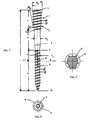
- the spacer screw 1 has, over its axial length L, essentially three different sections, namely a front threaded section A with a wood thread according to DIN 7998, a middle, threadless section B and a rear, tool-side threaded section C with a chipboard screw thread, which is cut deeper and steeper and more pointed thread flanks F 2 than the wood screw thread of the front thread section A with its flatter and rounder thread flanks F 1 .
- the spacer screw 1 has a recess 3 in the form of a Torx® drive for inserting a suitable tool.
- a brass knuckle 2 is formed an integral part of the entire spacer screw.
- the central, threadless section B is, apart from its conical transition to the front threaded section A, cylindrical and has the nominal diameter N 1 of the spacer screw 1.
- the imaginary cylinder touching the thread flank F 1 of the front threaded section A also has the nominal diameter N 1 .
- the thread flanks F 2 of the rear, tool-side threaded section C lie on the inner surface of an imaginary, rewritable cylinder 4 with the larger diameter N 2 than N 1 .
- the screw tapers conically, and with a cone angle ⁇ of - in the illustrated embodiment - about 10 °
- the flank angle ⁇ of the thread of the rear thread section C is less than 50 °; preferably, as in the illustrated embodiment, it is 40 ⁇ 4 °.
- the flank angle of the thread of the front thread section A according to DIN 7998 is 60 ⁇ 6 °.
- the thread flanks F 2 are thus steeper and more pointed than the thread flanks F 1 .
- the thread of the rear thread section C runs for unthreaded Section B out at the point labeled 5 with sharp edges.
- reinforcing ribs 6 are attached, which are evenly distributed over the circumference of the core 8 and, starting from the front end 9 of the non-threaded section B, run parallel to the longitudinal axis 7 of the screw in the direction of the screw tip 10.
- the length of the reinforcing ribs 6 is limited to approximately half the length of the front threaded section A. In the radial direction, the height of the reinforcing ribs 6 is somewhat less than the nominal diameter N 1 of the screw 1.
Landscapes
- Engineering & Computer Science (AREA)
- General Engineering & Computer Science (AREA)
- Mechanical Engineering (AREA)
- Physics & Mathematics (AREA)
- Geometry (AREA)
- Connection Of Plates (AREA)
- Mechanical Pencils And Projecting And Retracting Systems Therefor, And Multi-System Writing Instruments (AREA)
- Materials For Medical Uses (AREA)
- Valve Device For Special Equipments (AREA)
- Steroid Compounds (AREA)
- Color Television Image Signal Generators (AREA)
- Magnetic Heads (AREA)
- Mutual Connection Of Rods And Tubes (AREA)
- Milling Processes (AREA)
Abstract
Description
Claims (17)
- Distanzschraube mit einer Ausnehmung zum Einstecken eines Werkzeugs, mit zwei, von einem gewindelosen Abschnitt voneinander getrennten Gewindeabschnitten, wobei der Nenndurchmesser der Schraube im Bereich des vorderen Gewindeabschnitts und des gewindelosen Abschnitts kleiner ist als im Bereich des hinteren, werkzeugseitigen Gewindeabschnitts und wobei sich die Schraube im Bereich des Übergangs von dem hinteren Gewindeabschnitt zu dem gewindelosen Abschnitt hin konisch verjüngt, dadurch gekennzeichnet, daß mindestens zwei Verstärkungsrippen (6) auf dem Kern (8) des vorderen Gewindeabschnitts (A) angebracht sind, die, ausgehend vom vorderen Ende (9) des gewindelosen Abschnitts (B), parallel zur Schraubenlängsachse (7) in Richtung Schraubenspitze (10) verlaufen.
- Distanzschraube nach Anspruch 1, dadurch gekennzeichnet, daß drei bis sechs Verstärkungsrippen (6) gleichmäßig über den Umfang des Kerns (8) des vorderen Gewindeabschnitts (A) verteilt sind.
- Distanzschraube nach Anspruch 1 oder 2, dadurch gekennzeichnet, daß die Länge der Verstärkungsrippen (6) auf einen Teil der Länge des vorderen Gewindeabschnitts (A) begrenzt ist.
- Distanzschraube nach einem der Ansprüche 1 bis 3, dadurch gekennzeichnet, daß die Höhe der Verstärkungsrippen in radialer Richtung geringer ist als dem Nenndurchmesser (N1) der Schraube (1) entspricht.
- Distanzschraube nach einem der Ansprüche 1 bis 4, dadurch gekennzeichnet, daß das Gewinde des hinteren Gewindeabschnitts (C) tiefer geschnitten ist und steilere und spitzere Gewindeflanken (F2) aufweist als das Gewinde des vorderen Gewindeabschnitts (A).
- Distanzschraube nach einem der Ansprüche 1 bis 5, dadurch gekennzeichnet, daß das Gewinde des hinteren Gewindeabschnitts (C) selbstschneidend ausgebildet ist.
- Distanzschraube nach einem der Ansprüche 1 bis 6, dadurch gekennzeichnet, daß das Gewinde des vorderen Gewindeabschnitts (A) ein Holzschraubengewinde, das Gewinde des hinteren Gewindeabschnitts (C) ein Spanplattenschrauben- oder Blechschraubengewinde ist.
- Distanzschraube nach einem der Ansprüche 1 bis 7, dadurch gekennzeichnet, daß der Flankenwinkel (α) des Gewindes des hinteren Gewindeabschnitts (C) kleiner ist als 50°.
- Distanzschraube nach Anspruch 8, dadurch gekennzeichnet, daß der Flankenwinkel (α) 40 ± 4° beträgt.
- Distanzschraube nach einem der Ansprüche 1 bis 9, dadurch gekennzeichnet, daß die Flanken (F2) des Gewindes des hinteren Gewindeabschnitts (C) einsatzgehärtet sind.
- Distanzschraube nach einem der Ansprüche 1 bis 10, dadurch gekennzeichnet, daß der Konuswinkel (β) im Bereich des Übergangs vom hinteren Gewindeabschnitt (C) zum gewindelosen Abschnitt (B) weniger als 25° beträgt.
- Distanzschraube nach Anspruch 11, dadurch gekennzeichnet, daß der Konuswinkel (β) 10 ± 2° beträgt.
- Distanzschraube nach einem der Ansprüche 1 bis 12, dadurch gekennzeichnet, daß der Gewindegang des hinteren Gewindeabschnitts (C) zum gewindelosen Abschnitt (B) hin scharfkantig ausläuft.
- Distanzschraube nach einem der Ansprüche 1 bis 13, dadurch gekennzeichnet, daß alle Gewinde etwa gleiche Ganghöhe (H1, H2) und gleichsinnige Drehrichtung aufweisen.
- Distanzschraube nach einem der Ansprüche 1 bis 14, dadurch gekennzeichnet, daß auf dem werkzeugseitigen Ende des hinteren Gewindeabschnitts (C) ein Schlagring (2) gebildet ist.
- Distanzschraube nach einem der Ansprüche 1 bis 15, dadurch gekennzeichnet, daß sie als Ausnehmung (3) einen Querschlitz oder Kreuzschlitz, einen Innenvielkant oder eine Einsteckrosette zum Einstecken eines Schraubendrehers, Schlüssels oder Bits aufweist.
- Distanzschraube nach einem der Ansprüche 1 bis 16, dadurch gekennzeichnet, daß sich das Gewinde des vorderen Gewindeabschnitts (A) zusätzlich mindestens teilweise über den Mittelabschnitt (B) erstreckt.
Applications Claiming Priority (2)
| Application Number | Priority Date | Filing Date | Title |
|---|---|---|---|
| DE20014869U DE20014869U1 (de) | 2000-08-28 | 2000-08-28 | Distanzschraube |
| DE20014869U | 2000-08-28 |
Publications (2)
| Publication Number | Publication Date |
|---|---|
| EP1193407A1 true EP1193407A1 (de) | 2002-04-03 |
| EP1193407B1 EP1193407B1 (de) | 2003-12-17 |
Family
ID=7945759
Family Applications (1)
| Application Number | Title | Priority Date | Filing Date |
|---|---|---|---|
| EP01119664A Expired - Lifetime EP1193407B1 (de) | 2000-08-28 | 2001-08-22 | Distanzschraube |
Country Status (5)
| Country | Link |
|---|---|
| EP (1) | EP1193407B1 (de) |
| AT (1) | ATE256824T1 (de) |
| DE (2) | DE20014869U1 (de) |
| DK (1) | DK1193407T3 (de) |
| PT (1) | PT1193407E (de) |
Cited By (1)
| Publication number | Priority date | Publication date | Assignee | Title |
|---|---|---|---|---|
| DE202004019037U1 (de) * | 2004-12-08 | 2006-04-20 | Sfs Intec Holding Ag | Befestigung für einen Beschlag |
Families Citing this family (3)
| Publication number | Priority date | Publication date | Assignee | Title |
|---|---|---|---|---|
| DE20014869U1 (de) * | 2000-08-28 | 2000-11-23 | Berner GmbH, 74653 Künzelsau | Distanzschraube |
| DE102013100140A1 (de) * | 2013-01-09 | 2014-07-10 | Dr. Ing. H.C. F. Porsche Aktiengesellschaft | Schraube |
| DE102013210554A1 (de) * | 2013-06-06 | 2014-12-11 | Adolf Würth GmbH & Co. KG | Schraube |
Citations (6)
| Publication number | Priority date | Publication date | Assignee | Title |
|---|---|---|---|---|
| US3124031A (en) * | 1964-03-10 | Screw fastener | ||
| EP0267153A1 (de) * | 1986-11-03 | 1988-05-11 | Ferronorm AG | Schraube zur Abstandsbefestigung von Bauteilen |
| EP0314950A1 (de) * | 1987-10-15 | 1989-05-10 | Berner GmbH | Distanzschraube |
| US5273383A (en) * | 1991-04-04 | 1993-12-28 | Research Engineering & Manufacturing, Inc. | Threaded fastener for use in thermoplastics and roll die for producing same |
| FR2784722A1 (fr) * | 1998-10-19 | 2000-04-21 | Vynex Sa | Vis a bois |
| DE20014869U1 (de) * | 2000-08-28 | 2000-11-23 | Berner GmbH, 74653 Künzelsau | Distanzschraube |
-
2000
- 2000-08-28 DE DE20014869U patent/DE20014869U1/de not_active Expired - Lifetime
-
2001
- 2001-08-22 DE DE50101178T patent/DE50101178D1/de not_active Expired - Lifetime
- 2001-08-22 EP EP01119664A patent/EP1193407B1/de not_active Expired - Lifetime
- 2001-08-22 DK DK01119664T patent/DK1193407T3/da active
- 2001-08-22 PT PT01119664T patent/PT1193407E/pt unknown
- 2001-08-22 AT AT01119664T patent/ATE256824T1/de not_active IP Right Cessation
Patent Citations (6)
| Publication number | Priority date | Publication date | Assignee | Title |
|---|---|---|---|---|
| US3124031A (en) * | 1964-03-10 | Screw fastener | ||
| EP0267153A1 (de) * | 1986-11-03 | 1988-05-11 | Ferronorm AG | Schraube zur Abstandsbefestigung von Bauteilen |
| EP0314950A1 (de) * | 1987-10-15 | 1989-05-10 | Berner GmbH | Distanzschraube |
| US5273383A (en) * | 1991-04-04 | 1993-12-28 | Research Engineering & Manufacturing, Inc. | Threaded fastener for use in thermoplastics and roll die for producing same |
| FR2784722A1 (fr) * | 1998-10-19 | 2000-04-21 | Vynex Sa | Vis a bois |
| DE20014869U1 (de) * | 2000-08-28 | 2000-11-23 | Berner GmbH, 74653 Künzelsau | Distanzschraube |
Cited By (2)
| Publication number | Priority date | Publication date | Assignee | Title |
|---|---|---|---|---|
| DE202004019037U1 (de) * | 2004-12-08 | 2006-04-20 | Sfs Intec Holding Ag | Befestigung für einen Beschlag |
| EP1669533A3 (de) * | 2004-12-08 | 2011-05-11 | SFS intec Holding AG | Befestigung für einen Beschlag |
Also Published As
| Publication number | Publication date |
|---|---|
| ATE256824T1 (de) | 2004-01-15 |
| EP1193407B1 (de) | 2003-12-17 |
| DK1193407T3 (da) | 2004-04-13 |
| PT1193407E (pt) | 2004-04-30 |
| DE50101178D1 (de) | 2004-01-29 |
| DE20014869U1 (de) | 2000-11-23 |
Similar Documents
| Publication | Publication Date | Title |
|---|---|---|
| EP0102605B1 (de) | Holzschraube | |
| DE1500798B1 (de) | Bohr- und Gewindeformschraube | |
| EP2326848A1 (de) | Schraube | |
| EP0314950B1 (de) | Distanzschraube | |
| EP3482092B1 (de) | Dübelschraube | |
| EP1305529B1 (de) | Dübel für leichtbaustoffe und verwendung eines schraubendreherbits zum einschrauben eines solchen dübels | |
| DE69101679T2 (de) | Einsatzteil mit Gewinde für die Anwendung an einer Trockenmauer. | |
| EP3882475A1 (de) | Gipskartondübel und kombination des gipskartondübels mit einem bohr- und drehwerkzeug | |
| EP3006748A1 (de) | Bohrschraube | |
| DE10200964B4 (de) | System zum Verbinden zweier Profilstäbe | |
| EP3199824B1 (de) | Befestigungsanordnung und verwendung einer befestigungsanordnung | |
| DE19846993A1 (de) | Selbstschneidende Schraube, insbesondere Betonschraube | |
| WO2010040607A1 (de) | Bohrschraube mit schneidender scheibe | |
| EP1193407B1 (de) | Distanzschraube | |
| DE19652318C1 (de) | Schraube zur gegenseitigen Befestigung von wenigstens zwei Bauteilen | |
| DE29711128U1 (de) | Selbstbohrendes und gewindeformendes Verbindungselement | |
| EP0388694B1 (de) | Spreizdübel | |
| EP0284894A1 (de) | Befestigungseinrichtung mit Schraube und Impulswerkzeug für universelle Befestigungen | |
| EP2039845B1 (de) | Befestigungselement für die Befestigung von Dämmstoffplatten an einer Unterkonstruktion | |
| EP0799386B1 (de) | Loch- und gewindeformende schraube sowie verfahren zum eindrehen derselben | |
| EP0930438A1 (de) | Gewindeschneidende Schraube | |
| DE19506081A1 (de) | Befestigungselement | |
| DE202015100333U1 (de) | Gewindeformende Schraube | |
| EP3001045B1 (de) | Selbstschneidende schraube zum einschrauben in ein bohrloch in einem werkstoff, anordnung mit einer derartigen schraube und verfahren zum einschrauben einer derartigen schraube in ein bohrloch | |
| DE10357550A1 (de) | Selbstschneidende Schraube für Composit-Materialien |
Legal Events
| Date | Code | Title | Description |
|---|---|---|---|
| PUAI | Public reference made under article 153(3) epc to a published international application that has entered the european phase |
Free format text: ORIGINAL CODE: 0009012 |
|
| AK | Designated contracting states |
Kind code of ref document: A1 Designated state(s): AT BE CH CY DE DK ES FI FR GB GR IE IT LI LU MC NL PT SE TR |
|
| AX | Request for extension of the european patent |
Free format text: AL;LT;LV;MK;RO;SI |
|
| 17P | Request for examination filed |
Effective date: 20020712 |
|
| AKX | Designation fees paid |
Free format text: AT BE CH CY DE DK ES FI FR GB GR IE IT LI LU MC NL PT SE TR |
|
| GRAH | Despatch of communication of intention to grant a patent |
Free format text: ORIGINAL CODE: EPIDOS IGRA |
|
| GRAS | Grant fee paid |
Free format text: ORIGINAL CODE: EPIDOSNIGR3 |
|
| GRAA | (expected) grant |
Free format text: ORIGINAL CODE: 0009210 |
|
| AK | Designated contracting states |
Kind code of ref document: B1 Designated state(s): AT BE CH CY DE DK ES FI FR GB GR IE IT LI LU MC NL PT SE TR |
|
| PG25 | Lapsed in a contracting state [announced via postgrant information from national office to epo] |
Ref country code: GB Free format text: LAPSE BECAUSE OF FAILURE TO SUBMIT A TRANSLATION OF THE DESCRIPTION OR TO PAY THE FEE WITHIN THE PRESCRIBED TIME-LIMIT Effective date: 20031217 Ref country code: IE Free format text: LAPSE BECAUSE OF FAILURE TO SUBMIT A TRANSLATION OF THE DESCRIPTION OR TO PAY THE FEE WITHIN THE PRESCRIBED TIME-LIMIT Effective date: 20031217 Ref country code: TR Free format text: LAPSE BECAUSE OF FAILURE TO SUBMIT A TRANSLATION OF THE DESCRIPTION OR TO PAY THE FEE WITHIN THE PRESCRIBED TIME-LIMIT Effective date: 20031217 Ref country code: FI Free format text: LAPSE BECAUSE OF FAILURE TO SUBMIT A TRANSLATION OF THE DESCRIPTION OR TO PAY THE FEE WITHIN THE PRESCRIBED TIME-LIMIT Effective date: 20031217 Ref country code: CY Free format text: LAPSE BECAUSE OF FAILURE TO SUBMIT A TRANSLATION OF THE DESCRIPTION OR TO PAY THE FEE WITHIN THE PRESCRIBED TIME-LIMIT Effective date: 20031217 |
|
| RAP1 | Party data changed (applicant data changed or rights of an application transferred) |
Owner name: BERNER GMBH |
|
| REG | Reference to a national code |
Ref country code: GB Ref legal event code: FG4D Free format text: NOT ENGLISH |
|
| REG | Reference to a national code |
Ref country code: CH Ref legal event code: EP |
|
| REG | Reference to a national code |
Ref country code: IE Ref legal event code: FG4D Free format text: GERMAN |
|
| REF | Corresponds to: |
Ref document number: 50101178 Country of ref document: DE Date of ref document: 20040129 Kind code of ref document: P |
|
| PG25 | Lapsed in a contracting state [announced via postgrant information from national office to epo] |
Ref country code: GR Free format text: LAPSE BECAUSE OF FAILURE TO SUBMIT A TRANSLATION OF THE DESCRIPTION OR TO PAY THE FEE WITHIN THE PRESCRIBED TIME-LIMIT Effective date: 20040317 Ref country code: SE Free format text: LAPSE BECAUSE OF FAILURE TO SUBMIT A TRANSLATION OF THE DESCRIPTION OR TO PAY THE FEE WITHIN THE PRESCRIBED TIME-LIMIT Effective date: 20040317 |
|
| PG25 | Lapsed in a contracting state [announced via postgrant information from national office to epo] |
Ref country code: ES Free format text: LAPSE BECAUSE OF FAILURE TO SUBMIT A TRANSLATION OF THE DESCRIPTION OR TO PAY THE FEE WITHIN THE PRESCRIBED TIME-LIMIT Effective date: 20040328 |
|
| REG | Reference to a national code |
Ref country code: CH Ref legal event code: NV Representative=s name: TROESCH SCHEIDEGGER WERNER AG |
|
| REG | Reference to a national code |
Ref country code: DK Ref legal event code: T3 |
|
| REG | Reference to a national code |
Ref country code: PT Ref legal event code: SC4A Free format text: AVAILABILITY OF NATIONAL TRANSLATION Effective date: 20040220 |
|
| GBV | Gb: ep patent (uk) treated as always having been void in accordance with gb section 77(7)/1977 [no translation filed] |
Effective date: 20031217 |
|
| REG | Reference to a national code |
Ref country code: IE Ref legal event code: FD4D |
|
| ET | Fr: translation filed | ||
| PG25 | Lapsed in a contracting state [announced via postgrant information from national office to epo] |
Ref country code: MC Free format text: LAPSE BECAUSE OF NON-PAYMENT OF DUE FEES Effective date: 20040831 |
|
| PLBE | No opposition filed within time limit |
Free format text: ORIGINAL CODE: 0009261 |
|
| STAA | Information on the status of an ep patent application or granted ep patent |
Free format text: STATUS: NO OPPOSITION FILED WITHIN TIME LIMIT |
|
| 26N | No opposition filed |
Effective date: 20040920 |
|
| PGFP | Annual fee paid to national office [announced via postgrant information from national office to epo] |
Ref country code: DK Payment date: 20080820 Year of fee payment: 8 Ref country code: LU Payment date: 20080826 Year of fee payment: 8 Ref country code: NL Payment date: 20080826 Year of fee payment: 8 Ref country code: PT Payment date: 20080814 Year of fee payment: 8 |
|
| PGFP | Annual fee paid to national office [announced via postgrant information from national office to epo] |
Ref country code: AT Payment date: 20080826 Year of fee payment: 8 Ref country code: IT Payment date: 20080823 Year of fee payment: 8 |
|
| REG | Reference to a national code |
Ref country code: PT Ref legal event code: MM4A Free format text: LAPSE DUE TO NON-PAYMENT OF FEES Effective date: 20100222 |
|
| REG | Reference to a national code |
Ref country code: NL Ref legal event code: V1 Effective date: 20100301 |
|
| REG | Reference to a national code |
Ref country code: DK Ref legal event code: EBP |
|
| PG25 | Lapsed in a contracting state [announced via postgrant information from national office to epo] |
Ref country code: PT Free format text: LAPSE BECAUSE OF NON-PAYMENT OF DUE FEES Effective date: 20100222 |
|
| PG25 | Lapsed in a contracting state [announced via postgrant information from national office to epo] |
Ref country code: AT Free format text: LAPSE BECAUSE OF NON-PAYMENT OF DUE FEES Effective date: 20090822 |
|
| PG25 | Lapsed in a contracting state [announced via postgrant information from national office to epo] |
Ref country code: NL Free format text: LAPSE BECAUSE OF NON-PAYMENT OF DUE FEES Effective date: 20100301 Ref country code: DK Free format text: LAPSE BECAUSE OF NON-PAYMENT OF DUE FEES Effective date: 20090831 |
|
| PG25 | Lapsed in a contracting state [announced via postgrant information from national office to epo] |
Ref country code: IT Free format text: LAPSE BECAUSE OF NON-PAYMENT OF DUE FEES Effective date: 20090822 |
|
| PG25 | Lapsed in a contracting state [announced via postgrant information from national office to epo] |
Ref country code: LU Free format text: LAPSE BECAUSE OF NON-PAYMENT OF DUE FEES Effective date: 20090822 |
|
| REG | Reference to a national code |
Ref country code: DE Ref legal event code: R082 Ref document number: 50101178 Country of ref document: DE Representative=s name: PRINZ & PARTNER PATENTANWAELTE RECHTSANWAELTE, DE |
|
| REG | Reference to a national code |
Ref country code: DE Ref legal event code: R081 Ref document number: 50101178 Country of ref document: DE Owner name: BERNER TRADING HOLDING GMBH, DE Free format text: FORMER OWNER: BERNER GMBH, 74653 KUENZELSAU, DE Effective date: 20120215 Ref country code: DE Ref legal event code: R082 Ref document number: 50101178 Country of ref document: DE Representative=s name: PRINZ & PARTNER PATENTANWAELTE RECHTSANWAELTE, DE Effective date: 20120215 Ref country code: DE Ref legal event code: R082 Ref document number: 50101178 Country of ref document: DE Representative=s name: PRINZ & PARTNER MBB PATENTANWAELTE RECHTSANWAE, DE Effective date: 20120215 |
|
| REG | Reference to a national code |
Ref country code: CH Ref legal event code: PUE Owner name: BERNER TRADING HOLDING GMBH Free format text: BERNER GMBH#BERNERSTRASSE 6#74653 KUENZELSAU (DE) -TRANSFER TO- BERNER TRADING HOLDING GMBH#BERNERSTRASSE 6#74653 KUENZELSAU (DE) |
|
| BECH | Be: change of holder |
Owner name: BERNER TRADING HOLDING G.M.B.H. Effective date: 20121031 |
|
| BECN | Be: change of holder's name |
Owner name: BERNER TRADING HOLDING G.M.B.H. Effective date: 20121031 |
|
| REG | Reference to a national code |
Ref country code: FR Ref legal event code: TP Owner name: BERNER TRADING HOLDING GMBH, DE Effective date: 20121011 Ref country code: FR Ref legal event code: CJ Effective date: 20121011 |
|
| REG | Reference to a national code |
Ref country code: FR Ref legal event code: PLFP Year of fee payment: 15 |
|
| REG | Reference to a national code |
Ref country code: FR Ref legal event code: PLFP Year of fee payment: 16 |
|
| REG | Reference to a national code |
Ref country code: FR Ref legal event code: PLFP Year of fee payment: 17 |
|
| REG | Reference to a national code |
Ref country code: FR Ref legal event code: PLFP Year of fee payment: 18 |
|
| PGFP | Annual fee paid to national office [announced via postgrant information from national office to epo] |
Ref country code: FR Payment date: 20190822 Year of fee payment: 19 Ref country code: DE Payment date: 20190816 Year of fee payment: 19 |
|
| PGFP | Annual fee paid to national office [announced via postgrant information from national office to epo] |
Ref country code: BE Payment date: 20190821 Year of fee payment: 19 |
|
| PGFP | Annual fee paid to national office [announced via postgrant information from national office to epo] |
Ref country code: CH Payment date: 20190821 Year of fee payment: 19 |
|
| REG | Reference to a national code |
Ref country code: DE Ref legal event code: R119 Ref document number: 50101178 Country of ref document: DE |
|
| REG | Reference to a national code |
Ref country code: CH Ref legal event code: PL |
|
| PG25 | Lapsed in a contracting state [announced via postgrant information from national office to epo] |
Ref country code: CH Free format text: LAPSE BECAUSE OF NON-PAYMENT OF DUE FEES Effective date: 20200831 Ref country code: LI Free format text: LAPSE BECAUSE OF NON-PAYMENT OF DUE FEES Effective date: 20200831 |
|
| REG | Reference to a national code |
Ref country code: BE Ref legal event code: MM Effective date: 20200831 |
|
| PG25 | Lapsed in a contracting state [announced via postgrant information from national office to epo] |
Ref country code: FR Free format text: LAPSE BECAUSE OF NON-PAYMENT OF DUE FEES Effective date: 20200831 Ref country code: DE Free format text: LAPSE BECAUSE OF NON-PAYMENT OF DUE FEES Effective date: 20210302 |
|
| PG25 | Lapsed in a contracting state [announced via postgrant information from national office to epo] |
Ref country code: BE Free format text: LAPSE BECAUSE OF NON-PAYMENT OF DUE FEES Effective date: 20200831 |