EP1194985B1 - Prise male de raccordement avec prise femelle de type rca ou phono - Google Patents
Prise male de raccordement avec prise femelle de type rca ou phono Download PDFInfo
- Publication number
- EP1194985B1 EP1194985B1 EP00906041A EP00906041A EP1194985B1 EP 1194985 B1 EP1194985 B1 EP 1194985B1 EP 00906041 A EP00906041 A EP 00906041A EP 00906041 A EP00906041 A EP 00906041A EP 1194985 B1 EP1194985 B1 EP 1194985B1
- Authority
- EP
- European Patent Office
- Prior art keywords
- socket
- plug
- rca
- return conductor
- pin
- Prior art date
- Legal status (The legal status is an assumption and is not a legal conclusion. Google has not performed a legal analysis and makes no representation as to the accuracy of the status listed.)
- Expired - Lifetime
Links
Images


Classifications
-
- H—ELECTRICITY
- H01—ELECTRIC ELEMENTS
- H01R—ELECTRICALLY-CONDUCTIVE CONNECTIONS; STRUCTURAL ASSOCIATIONS OF A PLURALITY OF MUTUALLY-INSULATED ELECTRICAL CONNECTING ELEMENTS; COUPLING DEVICES; CURRENT COLLECTORS
- H01R24/00—Two-part coupling devices, or either of their cooperating parts, characterised by their overall structure
- H01R24/38—Two-part coupling devices, or either of their cooperating parts, characterised by their overall structure having concentrically or coaxially arranged contacts
- H01R24/40—Two-part coupling devices, or either of their cooperating parts, characterised by their overall structure having concentrically or coaxially arranged contacts specially adapted for high frequency
- H01R24/56—Two-part coupling devices, or either of their cooperating parts, characterised by their overall structure having concentrically or coaxially arranged contacts specially adapted for high frequency specially adapted to a specific shape of cables, e.g. corrugated cables, twisted pair cables, cables with two screens or hollow cables
Definitions
- This invention relates to a plug for connection to an RCA or phono type socket.
- This invention has particular but not exclusive application to audio electrical connections, and for illustrative purpose reference will be made to such application.
- the RCA plug and socket connection system (a generic name for a phono type plug and socket connection system) has been criticized by electronic engineers and audio enthusiasts as being an inferior connection for high quality audio.
- the RCA plug and socket connection system was originally designed as a means of connecting antenna cables to televisions. It was never considered the best solution for audio applications but has become the de facto world standard plug and socket connection system as used in consumer electronic components worldwide; see e.g. US-A-5 222 149.
- the RCA plug is prone to capacitive and oxidative effects because of the poor fitting of some plug designs and due to the wide-ranging size of RCA sockets (7.95mm to 8.55mm diameter). It is also believed that the large amount of metal used in the construction of many RCA plugs is a cause of inductive and capacitive distortion, which in turn adversely affects sound reproduction.
- cylindrical conductive band connection system used in typical RCA plugs to surround and make contact with the outer casing of an RCA socket tends to disperse the flow of electrons. As a result the transmitted current flows through many different entry points, resulting in interfering eddy currents and consequent distortion.
- the present invention aims to alleviate the above disadvantages and to provide a plug for connection to an RCA socket which will offer better sound and will be reliable and efficient in use.
- this invention as claimed resides broadly in a plug for connection to an RCA socket having an external casing that is constructed from an electrically conductive material and an internal bore that is also lined with an electrically conductive material, said conductive materials being separated from each other by suitable insulation, said plug including; a signal pin that is frictionally locatable within the bore, a return conductor of pin-like construction which is adapted to make contact with the casing when said pin is located within the bore, and spacing means for maintaining said pin and said return conductor in an operative spaced relationship within an electrically non-conductive material, for example a plastic polymer such as Teflon, polyphenylene sulfide (PPS) etc.
- PPS polyphenylene sulfide
- the plug also includes retaining means that is intended to retain the return conductor in electrical contact with the casing.
- the retaining means may include a spring that urges the return conductor towards the casing.
- the retaining means may include a recess having a continuous side wall, or a plurality of circumferentially spaced wall portions, which support the return conductor and retain the return conductor in contact with the casing when an end portion of the casing is frictionally located within said recess.
- the side wall of the casing may further include one or more breaks formed therein that allow the recess to engage sockets that exhibit minor variations in respect of the external diameter of the casing.
- the return conductor in the form of said pin makes contact with the outside casing of an RCA socket by means of a raised contact area at the front portion of the pin that may include but is not limited to shapes such as an ellipse, a sphere, a cylinder etc.
- One advantage of the return conductor of the present invention is the fact that it comprises far less conductive metal material than the return conductor embodied in a typical RCA plug, thereby reducing distortion.
- the return conductor may be constructed from a variety of electrically conductive materials, such as various brass, nickel, silver and copper alloys.
- the return conductor may also include at least one site along its length where the free end of an electrical wire may be soldered thereto.
- the trailing end portion of the return conductor may include a seat extending rearwardly therefrom.
- the signal pin may also be constructed from a variety of electrically conductive materials, such as various brass, nickel, silver and copper alloys.
- the signal pin may be of solid or hollow construction.
- the signal pin may be tubular and generally of constant transverse cross-section.
- the signal pin may include at least one site along its length where the free end of an electrical wire may be soldered thereto.
- the trailing end portion of the signal pin may include a seat extending rearwardly therefrom.
- Selected portions of the signal pin, return conductor and spacing means may be enclosed within a housing that may be constructed from a variety of materials including various electrically non-conductive materials and heat resistant materials, such as plastic polymer and Teflon materials.
- the housing may be provided with one or more apertures therein through which electrical wires and/or cable may extend and whereby in use the housing may provide protection for the connections between the wires and the signal pin and the return conductor.
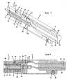
- Figures 7 and 8 show longitudinal cross-sectional views of a plug 10 that is operatively connected to an RCA socket 11 having an external casing 12, that is constructed from an electrically conductive material, and an internal bore 13, that is also lined with an electrically conductive material, said casing 12 and said bore 13 being separated from each other by suitable insulation 14.
- the plug 10 includes a signal pin 15 that is frictionally locatable within the bore 13, a return conductor 16 which makes electrical contact with the casing 12 when the signal pin 15 is located within said bore, and spacing means 17 that maintains said signal pin 15 and said return conductor 16 in an operative spaced relationship.
- the signal pin 15 is constructed from a suitable electrically conductive material, such as various brass, nickel, silver or copper alloys.
- the signal pin 15 consists of a cylindrical tube having a bore 15a of constant transverse cross-section and a rearwardly extending, channel shaped seat 18.
- the return conductor 16 consists of a cylindrical pin constructed from a suitable electrically conductive material, such as various brass, nickel, silver or copper alloys, and includes a rearwardly extending, channel shaped seat 19.
- the spacing means 17 is constructed from an electrically non-conductive material, such as plastic polymer or Teflon.
- the spacing means 17 includes a generally cylindrically shaped head portion 20 having an axially located, cylindrically shaped recess 21 that is defined by a substantially continuous internal side wall 22.
- the side wall 22 includes four equally spaced splits 23 that allow partial relative movement of the constituent wall portions 24 thereby enabling the recess 21 to frictionally receive a variety of RCA sockets 11 each having a cylindrically shaped end portion 25 of differing external diameter.
- the head portion 20 also includes a centrally located, longitudinally extending through bore 26, formed in an intermediate base wall 26a through which a portion of the signal pin 15 extends.
- the signal pin 15 includes a holding lug 35 which protrudes perpendicularly from a position along the length of signal pin 15 to support and prevent movement of signal pin 15 within spacing means 17.
- the return conductor 16 includes a holding lug 36 which protrudes perpendicularly from a position along the length of return conductor 16 to support and prevent movement of return conductor 16 within spacing means 17.
- the return conductor 16 extends through an aperture 40 formed in the base wall whereby an elliptical shaped contact portion 41 of the return conductor 16 lies flush with, and protrudes marginally from the internal side wall 22 to make contact with the cylindrically shaped end portion 25 of an RCA socket.
- the plug 10 also includes a cylindrically shaped, tubular housing 29 which is partially closed at one end by rear wall 30 which is provided with a centrally located aperture 31.
- a piece of cable 32 containing two or more electrical wires 33 and 34 is threaded through the aperture 31 prior to the placement of the housing 29 in it's operative position whereby it shrouds the rearward portions of both the signal pin 15 and the return conductor 16.
- the cable 32 is secured by use of grub screw 27 located through aperture 28 thereby making contact with the outer sleeve of appropriately sized cable 32.
- the free exposed end portion 37 of the signal wire 33 may be supported by the seat 18, as illustrated in FIGURES 1 and 2, and subsequently connected thereto using a suitable electrical solder.
- the free exposed end portion 37 of the signal wire 33 may be extended through the bore 15a and subsequently soldered to a side wall of said bore adjacent to the tip 38, as illustrated in FIGURES 7 and 8.
- the free exposed end portion 39 of the return wire 34 may be supported by the seat 19, as illustrated in FIGURES 1 and 2, and subsequently connected thereto using a suitable electrical solder.
- the signal pin 15 When the plug 10 is operatively connected to an RCA socket 11, the signal pin 15 is frictionally located within the bore 13 and the contact portion 41 of the return conductor 16 bears against and thereby makes electrical contact with the adjacent casing 12 as illustrated in FIGURES 7 and 8.
Landscapes
- Details Of Connecting Devices For Male And Female Coupling (AREA)
- Connector Housings Or Holding Contact Members (AREA)
- Coupling Device And Connection With Printed Circuit (AREA)
- Mechanical Coupling Of Light Guides (AREA)
- Dowels (AREA)
Claims (2)
- Fiche pour réaliser une connexion à une prise RCA ou phono, ladite prise (11) ayant un boítier de terre externe (12) qui est construit à partir d'un matériau électriquement conducteur avec un alésage de signal interne (13) qui est également recouvert d'un matériau électriquement conducteur, lesdits matériaux conducteurs étant séparés l'un de l'autre par un isolant approprié (14), ladite fiche (10) comprenant :une broche de signal (15) destinée à être mise en place par frottement dans ledit alésage de prise ;un conducteur de retour ou de terre (16) d'une construction similaire à la broche et maintenu en relation espacée opérante par rapport la broche de signal au moyen d'un matériau non conducteur (17) tel qu'un polymère plastique, et adapté à réaliser un contact électrique avec le boítier de terre externe de la fiche lorsque la broche de signal est positionnée à l'intérieur de l'alésage de signal interne de la prise ; et des moyens de maintien qui, lorsque l'extension de collier (20) de la fiche dudit matériau non conducteur vient en prise avec le boítier de terre externe de la prise, exerce une pression sur et pousse ledit conducteur de retour ou de terre contre le boítier de terre externe de la prise.
- Fiche selon la revendication 1, dans laquelle les parties arrière de ladite broche de signal et dudit conducteur de retour peuvent accepter une connexion aux fils de signal et de retour respectifs d'un câble électrique.
Applications Claiming Priority (5)
| Application Number | Priority Date | Filing Date | Title |
|---|---|---|---|
| AUPQ042999 | 1999-05-18 | ||
| AUPQ0429A AUPQ042999A0 (en) | 1999-05-18 | 1999-05-18 | A plug for connection to an rca type socket |
| AUPQ5251A AUPQ525100A0 (en) | 2000-01-27 | 2000-01-27 | A plug for connection to an rca or phono type socket |
| AUPQ525100 | 2000-01-27 | ||
| PCT/AU2000/000064 WO2000070717A1 (fr) | 1999-05-18 | 2000-02-04 | Prise male de raccordement avec prise femelle de type rca ou phono |
Publications (4)
| Publication Number | Publication Date |
|---|---|
| EP1194985A1 EP1194985A1 (fr) | 2002-04-10 |
| EP1194985A4 EP1194985A4 (fr) | 2002-10-23 |
| EP1194985B1 true EP1194985B1 (fr) | 2004-06-30 |
| EP1194985B2 EP1194985B2 (fr) | 2009-09-16 |
Family
ID=25646062
Family Applications (1)
| Application Number | Title | Priority Date | Filing Date |
|---|---|---|---|
| EP00906041A Expired - Lifetime EP1194985B2 (fr) | 1999-05-18 | 2000-02-04 | Prise male de raccordement avec prise femelle de type rca ou phono |
Country Status (8)
| Country | Link |
|---|---|
| US (1) | US6604962B1 (fr) |
| EP (1) | EP1194985B2 (fr) |
| CN (1) | CN1210849C (fr) |
| AT (1) | ATE270466T1 (fr) |
| AU (1) | AU2783000A (fr) |
| DE (1) | DE60011903T3 (fr) |
| TW (1) | TW480777B (fr) |
| WO (1) | WO2000070717A1 (fr) |
Cited By (1)
| Publication number | Priority date | Publication date | Assignee | Title |
|---|---|---|---|---|
| DE202006000041U1 (de) * | 2006-01-03 | 2007-05-16 | Audio Int'l Vertriebsgesellschaft Mbh | Stecker |
Families Citing this family (9)
| Publication number | Priority date | Publication date | Assignee | Title |
|---|---|---|---|---|
| DE10258689B3 (de) * | 2002-12-13 | 2004-07-08 | Wolfgang B. THÖRNER | Koaxiale Steckverbindung |
| US6939181B2 (en) * | 2003-10-31 | 2005-09-06 | Medtronic, Inc. | Assembly and method for connecting electrical medical components |
| USD516510S1 (en) * | 2005-02-02 | 2006-03-07 | Metra Electronics Corporation | Audio connector cable with twisted mold and plated tip |
| US7160149B1 (en) * | 2005-06-24 | 2007-01-09 | John Mezzalingua Associates, Inc. | Coaxial connector and method of connecting a two-wire cable to a coaxial connector |
| TWI458196B (zh) * | 2011-06-20 | 2014-10-21 | Hon Hai Prec Ind Co Ltd | 線纜連接器 |
| CN103427212B (zh) * | 2012-05-22 | 2015-11-25 | 富士康(昆山)电脑接插件有限公司 | 线缆连接器 |
| EP2994922A4 (fr) * | 2013-05-08 | 2016-12-28 | Nordost Corp | Connecteur phono |
| CN105322306A (zh) * | 2015-10-12 | 2016-02-10 | 何翔 | 一种不用焊接的音频视频接头 |
| CN107195381A (zh) * | 2017-07-13 | 2017-09-22 | 南昌广音源科技有限公司 | 高保真视频、音频复合电源线 |
Family Cites Families (17)
| Publication number | Priority date | Publication date | Assignee | Title |
|---|---|---|---|---|
| US2520739A (en) † | 1947-09-09 | 1950-08-29 | Harvey L Shaw | Electric coupling |
| DE1922154A1 (de) * | 1969-04-25 | 1970-11-05 | Siemens Ag | Steckanschluss fuer Koaxialpaare |
| US3600531A (en) † | 1970-05-08 | 1971-08-17 | Nat Tel Tronics Corp | Self-shorting phono plug |
| US3893743A (en) * | 1974-01-30 | 1975-07-08 | Perfection Enterprises Inc | Solid shell phonoconnectors |
| US4397516A (en) * | 1981-05-26 | 1983-08-09 | The Bendix Corporation | Cable termination apparatus |
| DE3613770A1 (de) † | 1986-04-23 | 1987-10-29 | Holger Grage | Stecker fuer eine elektrische verbindung, insbesondere cinch-stecker |
| EP0696089B1 (fr) † | 1989-09-25 | 2002-04-10 | Murata Manufacturing Co., Ltd. | Connecteur |
| DE8915171U1 (de) † | 1989-12-23 | 1990-04-26 | WBT Wolfgang B. Thörner GmbH, 4300 Essen | Cinch-Stecker |
| FR2660489B1 (fr) † | 1990-03-30 | 1994-05-06 | Raymond Caillot | Connecteur pour cable coaxial. |
| US5222149A (en) * | 1991-11-15 | 1993-06-22 | Palmer Donald E | Damping terminator for high fidelity audio signals |
| US5413503A (en) * | 1993-04-01 | 1995-05-09 | Wireworld By David Salz, Inc. | Phono plug |
| GB9320575D0 (en) * | 1993-10-06 | 1993-11-24 | Amp Gmbh | Coaxial connector having improved locking mechanism |
| US5376022A (en) † | 1993-12-06 | 1994-12-27 | Safco Corporation | Electrical connector |
| DE4419023C2 (de) * | 1994-05-31 | 1998-02-19 | Ifm Electronic Gmbh | Einbaustecker |
| IT1270305B (it) * | 1994-06-03 | 1997-04-29 | Elettromedia Sas | Connettore compatibile con linee di trasmissione audio, bilanciate e non. |
| US5564942A (en) * | 1995-02-21 | 1996-10-15 | Monster Cable International, Ltd. | Connector for an electrical signal transmitting cable |
| DE19528678C1 (de) † | 1995-07-19 | 1997-01-23 | Ifm Electronic Gmbh | Einbaustecker |
-
2000
- 2000-02-04 US US09/744,204 patent/US6604962B1/en not_active Expired - Fee Related
- 2000-02-04 DE DE60011903T patent/DE60011903T3/de not_active Expired - Lifetime
- 2000-02-04 AT AT00906041T patent/ATE270466T1/de not_active IP Right Cessation
- 2000-02-04 AU AU27830/00A patent/AU2783000A/en not_active Abandoned
- 2000-02-04 WO PCT/AU2000/000064 patent/WO2000070717A1/fr not_active Ceased
- 2000-02-04 CN CNB008075921A patent/CN1210849C/zh not_active Expired - Fee Related
- 2000-02-04 EP EP00906041A patent/EP1194985B2/fr not_active Expired - Lifetime
- 2000-03-30 TW TW089106005A patent/TW480777B/zh not_active IP Right Cessation
Cited By (1)
| Publication number | Priority date | Publication date | Assignee | Title |
|---|---|---|---|---|
| DE202006000041U1 (de) * | 2006-01-03 | 2007-05-16 | Audio Int'l Vertriebsgesellschaft Mbh | Stecker |
Also Published As
| Publication number | Publication date |
|---|---|
| CN1352817A (zh) | 2002-06-05 |
| ATE270466T1 (de) | 2004-07-15 |
| CN1210849C (zh) | 2005-07-13 |
| DE60011903D1 (de) | 2004-08-05 |
| TW480777B (en) | 2002-03-21 |
| EP1194985A1 (fr) | 2002-04-10 |
| DE60011903T3 (de) | 2010-04-22 |
| WO2000070717A1 (fr) | 2000-11-23 |
| AU2783000A (en) | 2000-12-05 |
| EP1194985A4 (fr) | 2002-10-23 |
| DE60011903T2 (de) | 2005-08-25 |
| EP1194985B2 (fr) | 2009-09-16 |
| US6604962B1 (en) | 2003-08-12 |
Similar Documents
| Publication | Publication Date | Title |
|---|---|---|
| US6609937B2 (en) | Cable and phone plug assembly and method for producing it | |
| US7311566B2 (en) | Electrical connectors | |
| US8016615B2 (en) | Phone plug connector device | |
| CA1242008A (fr) | Connecteur de cable coaxial | |
| US20020025729A1 (en) | RCA-type electrical plug connector | |
| US3980382A (en) | Matched impedance coaxial cable to printed circuit board terminator | |
| GB1077332A (en) | An electrical contact socket | |
| MY110075A (en) | Connector for coaxial cables. | |
| JP2004342571A (ja) | 同軸ケーブルのコネクタ | |
| EP1194985B1 (fr) | Prise male de raccordement avec prise femelle de type rca ou phono | |
| US6193559B1 (en) | Jack plug | |
| US7001220B2 (en) | Coaxial plug-and-socket connection | |
| US5580261A (en) | Coaxial electrical connector also performing a switching function | |
| JPS60236476A (ja) | ダイオード コネクタ | |
| US20020002005A1 (en) | Electrical connection and connectors | |
| EP1642362A1 (fr) | Connecteur coaxial | |
| HK26195A (en) | High-voltage connection device, particularly for a high-voltage transformer | |
| JPS5848776Y2 (ja) | 同軸ケ−ブル用コンタクト | |
| US20030040220A1 (en) | Input/output port having a tubular conductive terminal holder for use in a directional tap | |
| CN206742503U (zh) | 一种配接超细半硬电缆的连接器 | |
| US20160006144A1 (en) | Phono connector | |
| TH844C3 (th) | ตัวเสียบหูฟังชนิดหลายช่องเสียง | |
| TH843A3 (th) | ตัวเสียบหูฟังชนิดหลายช่องเสียง | |
| GB989432A (en) | Improvements in connectors for co-axial electric cables | |
| GB2568221A (en) | Gekko RCA Connector |
Legal Events
| Date | Code | Title | Description |
|---|---|---|---|
| PUAI | Public reference made under article 153(3) epc to a published international application that has entered the european phase |
Free format text: ORIGINAL CODE: 0009012 |
|
| 17P | Request for examination filed |
Effective date: 20011206 |
|
| AK | Designated contracting states |
Kind code of ref document: A1 Designated state(s): AT BE CH CY DE DK ES FI FR GB GR IE IT LI LU MC NL PT SE |
|
| A4 | Supplementary search report drawn up and despatched |
Effective date: 20020910 |
|
| AK | Designated contracting states |
Kind code of ref document: A4 Designated state(s): AT BE CH CY DE DK ES FI FR GB GR IE IT LI LU MC NL PT SE |
|
| GRAP | Despatch of communication of intention to grant a patent |
Free format text: ORIGINAL CODE: EPIDOSNIGR1 |
|
| GRAS | Grant fee paid |
Free format text: ORIGINAL CODE: EPIDOSNIGR3 |
|
| GRAA | (expected) grant |
Free format text: ORIGINAL CODE: 0009210 |
|
| AK | Designated contracting states |
Kind code of ref document: B1 Designated state(s): AT BE CH CY DE DK ES FI FR GB GR IE IT LI LU MC NL PT SE |
|
| PG25 | Lapsed in a contracting state [announced via postgrant information from national office to epo] |
Ref country code: IT Free format text: LAPSE BECAUSE OF FAILURE TO SUBMIT A TRANSLATION OF THE DESCRIPTION OR TO PAY THE FEE WITHIN THE PRESCRIBED TIME-LIMIT;WARNING: LAPSES OF ITALIAN PATENTS WITH EFFECTIVE DATE BEFORE 2007 MAY HAVE OCCURRED AT ANY TIME BEFORE 2007. THE CORRECT EFFECTIVE DATE MAY BE DIFFERENT FROM THE ONE RECORDED. Effective date: 20040630 Ref country code: BE Free format text: LAPSE BECAUSE OF FAILURE TO SUBMIT A TRANSLATION OF THE DESCRIPTION OR TO PAY THE FEE WITHIN THE PRESCRIBED TIME-LIMIT Effective date: 20040630 Ref country code: NL Free format text: LAPSE BECAUSE OF FAILURE TO SUBMIT A TRANSLATION OF THE DESCRIPTION OR TO PAY THE FEE WITHIN THE PRESCRIBED TIME-LIMIT Effective date: 20040630 Ref country code: CH Free format text: LAPSE BECAUSE OF FAILURE TO SUBMIT A TRANSLATION OF THE DESCRIPTION OR TO PAY THE FEE WITHIN THE PRESCRIBED TIME-LIMIT Effective date: 20040630 Ref country code: FR Free format text: LAPSE BECAUSE OF FAILURE TO SUBMIT A TRANSLATION OF THE DESCRIPTION OR TO PAY THE FEE WITHIN THE PRESCRIBED TIME-LIMIT Effective date: 20040630 Ref country code: AT Free format text: LAPSE BECAUSE OF FAILURE TO SUBMIT A TRANSLATION OF THE DESCRIPTION OR TO PAY THE FEE WITHIN THE PRESCRIBED TIME-LIMIT Effective date: 20040630 Ref country code: FI Free format text: LAPSE BECAUSE OF FAILURE TO SUBMIT A TRANSLATION OF THE DESCRIPTION OR TO PAY THE FEE WITHIN THE PRESCRIBED TIME-LIMIT Effective date: 20040630 Ref country code: LI Free format text: LAPSE BECAUSE OF FAILURE TO SUBMIT A TRANSLATION OF THE DESCRIPTION OR TO PAY THE FEE WITHIN THE PRESCRIBED TIME-LIMIT Effective date: 20040630 |
|
| REG | Reference to a national code |
Ref country code: GB Ref legal event code: FG4D Ref country code: CH Ref legal event code: EP |
|
| PLBQ | Unpublished change to opponent data |
Free format text: ORIGINAL CODE: EPIDOS OPPO |
|
| PLBI | Opposition filed |
Free format text: ORIGINAL CODE: 0009260 |
|
| REG | Reference to a national code |
Ref country code: IE Ref legal event code: FG4D |
|
| REF | Corresponds to: |
Ref document number: 60011903 Country of ref document: DE Date of ref document: 20040805 Kind code of ref document: P |
|
| 26 | Opposition filed |
Opponent name: WBT-INDUSTRIE ELEKTROMECHANISCHE PRODUKTE GMBH Effective date: 20040702 |
|
| PG25 | Lapsed in a contracting state [announced via postgrant information from national office to epo] |
Ref country code: SE Free format text: LAPSE BECAUSE OF FAILURE TO SUBMIT A TRANSLATION OF THE DESCRIPTION OR TO PAY THE FEE WITHIN THE PRESCRIBED TIME-LIMIT Effective date: 20040930 Ref country code: DK Free format text: LAPSE BECAUSE OF FAILURE TO SUBMIT A TRANSLATION OF THE DESCRIPTION OR TO PAY THE FEE WITHIN THE PRESCRIBED TIME-LIMIT Effective date: 20040930 Ref country code: GR Free format text: LAPSE BECAUSE OF FAILURE TO SUBMIT A TRANSLATION OF THE DESCRIPTION OR TO PAY THE FEE WITHIN THE PRESCRIBED TIME-LIMIT Effective date: 20040930 |
|
| NLR1 | Nl: opposition has been filed with the epo |
Opponent name: WBT-INDUSTRIE ELEKTROMECHANISCHE PRODUKTE GMBH |
|
| PG25 | Lapsed in a contracting state [announced via postgrant information from national office to epo] |
Ref country code: ES Free format text: LAPSE BECAUSE OF FAILURE TO SUBMIT A TRANSLATION OF THE DESCRIPTION OR TO PAY THE FEE WITHIN THE PRESCRIBED TIME-LIMIT Effective date: 20041011 |
|
| NLV1 | Nl: lapsed or annulled due to failure to fulfill the requirements of art. 29p and 29m of the patents act | ||
| REG | Reference to a national code |
Ref country code: CH Ref legal event code: PL |
|
| PG25 | Lapsed in a contracting state [announced via postgrant information from national office to epo] |
Ref country code: CY Free format text: LAPSE BECAUSE OF FAILURE TO SUBMIT A TRANSLATION OF THE DESCRIPTION OR TO PAY THE FEE WITHIN THE PRESCRIBED TIME-LIMIT Effective date: 20050204 Ref country code: LU Free format text: LAPSE BECAUSE OF NON-PAYMENT OF DUE FEES Effective date: 20050204 Ref country code: IE Free format text: LAPSE BECAUSE OF NON-PAYMENT OF DUE FEES Effective date: 20050204 |
|
| PG25 | Lapsed in a contracting state [announced via postgrant information from national office to epo] |
Ref country code: MC Free format text: LAPSE BECAUSE OF NON-PAYMENT OF DUE FEES Effective date: 20050228 |
|
| PLAX | Notice of opposition and request to file observation + time limit sent |
Free format text: ORIGINAL CODE: EPIDOSNOBS2 |
|
| PLAQ | Examination of admissibility of opposition: information related to despatch of communication + time limit deleted |
Free format text: ORIGINAL CODE: EPIDOSDOPE2 |
|
| PLAR | Examination of admissibility of opposition: information related to receipt of reply deleted |
Free format text: ORIGINAL CODE: EPIDOSDOPE4 |
|
| PLBQ | Unpublished change to opponent data |
Free format text: ORIGINAL CODE: EPIDOS OPPO |
|
| PLAB | Opposition data, opponent's data or that of the opponent's representative modified |
Free format text: ORIGINAL CODE: 0009299OPPO |
|
| PLBP | Opposition withdrawn |
Free format text: ORIGINAL CODE: 0009264 |
|
| EN | Fr: translation not filed | ||
| REG | Reference to a national code |
Ref country code: GB Ref legal event code: 732E |
|
| REG | Reference to a national code |
Ref country code: GB Ref legal event code: 732E |
|
| REG | Reference to a national code |
Ref country code: IE Ref legal event code: MM4A |
|
| PLBB | Reply of patent proprietor to notice(s) of opposition received |
Free format text: ORIGINAL CODE: EPIDOSNOBS3 |
|
| PLAZ | Examination of admissibility of opposition: despatch of communication + time limit |
Free format text: ORIGINAL CODE: EPIDOSNOPE2 |
|
| PLBA | Examination of admissibility of opposition: reply received |
Free format text: ORIGINAL CODE: EPIDOSNOPE4 |
|
| PG25 | Lapsed in a contracting state [announced via postgrant information from national office to epo] |
Ref country code: PT Free format text: LAPSE BECAUSE OF NON-PAYMENT OF DUE FEES Effective date: 20041130 |
|
| PLAQ | Examination of admissibility of opposition: information related to despatch of communication + time limit deleted |
Free format text: ORIGINAL CODE: EPIDOSDOPE2 |
|
| PLAR | Examination of admissibility of opposition: information related to receipt of reply deleted |
Free format text: ORIGINAL CODE: EPIDOSDOPE4 |
|
| PLAY | Examination report in opposition despatched + time limit |
Free format text: ORIGINAL CODE: EPIDOSNORE2 |
|
| PLBC | Reply to examination report in opposition received |
Free format text: ORIGINAL CODE: EPIDOSNORE3 |
|
| PUAH | Patent maintained in amended form |
Free format text: ORIGINAL CODE: 0009272 |
|
| STAA | Information on the status of an ep patent application or granted ep patent |
Free format text: STATUS: PATENT MAINTAINED AS AMENDED |
|
| 27A | Patent maintained in amended form |
Effective date: 20090916 |
|
| AK | Designated contracting states |
Kind code of ref document: B2 Designated state(s): AT BE CH CY DE DK ES FI FR GB GR IE IT LI LU MC NL PT SE |
|
| REG | Reference to a national code |
Ref country code: ES Ref legal event code: FD2A Effective date: 20050205 |
|
| PGFP | Annual fee paid to national office [announced via postgrant information from national office to epo] |
Ref country code: DE Payment date: 20110223 Year of fee payment: 12 |
|
| PGFP | Annual fee paid to national office [announced via postgrant information from national office to epo] |
Ref country code: GB Payment date: 20110224 Year of fee payment: 12 |
|
| GBPC | Gb: european patent ceased through non-payment of renewal fee |
Effective date: 20120204 |
|
| REG | Reference to a national code |
Ref country code: DE Ref legal event code: R119 Ref document number: 60011903 Country of ref document: DE Effective date: 20120901 |
|
| PG25 | Lapsed in a contracting state [announced via postgrant information from national office to epo] |
Ref country code: GB Free format text: LAPSE BECAUSE OF NON-PAYMENT OF DUE FEES Effective date: 20120204 |
|
| PG25 | Lapsed in a contracting state [announced via postgrant information from national office to epo] |
Ref country code: DE Free format text: LAPSE BECAUSE OF NON-PAYMENT OF DUE FEES Effective date: 20120901 |