EP1195151B1 - Beweglicher finger für eine prothese und finger für eine prothese der oberen extremität - Google Patents
Beweglicher finger für eine prothese und finger für eine prothese der oberen extremität Download PDFInfo
- Publication number
- EP1195151B1 EP1195151B1 EP00929803A EP00929803A EP1195151B1 EP 1195151 B1 EP1195151 B1 EP 1195151B1 EP 00929803 A EP00929803 A EP 00929803A EP 00929803 A EP00929803 A EP 00929803A EP 1195151 B1 EP1195151 B1 EP 1195151B1
- Authority
- EP
- European Patent Office
- Prior art keywords
- intermediate portion
- support shaft
- finger
- fingertip
- base
- Prior art date
- Legal status (The legal status is an assumption and is not a legal conclusion. Google has not performed a legal analysis and makes no representation as to the accuracy of the status listed.)
- Expired - Lifetime
Links
- 210000001364 upper extremity Anatomy 0.000 title claims description 54
- 238000005452 bending Methods 0.000 claims abstract description 47
- 230000007246 mechanism Effects 0.000 claims abstract description 41
- 210000003811 finger Anatomy 0.000 claims description 188
- 238000004804 winding Methods 0.000 claims description 30
- 210000003813 thumb Anatomy 0.000 claims description 8
- 230000003183 myoelectrical effect Effects 0.000 description 13
- 230000002068 genetic effect Effects 0.000 description 6
- 238000013459 approach Methods 0.000 description 5
- 210000004932 little finger Anatomy 0.000 description 4
- 230000006870 function Effects 0.000 description 3
- 238000004891 communication Methods 0.000 description 2
- 230000000694 effects Effects 0.000 description 2
- 238000000034 method Methods 0.000 description 2
- 238000012545 processing Methods 0.000 description 2
- 238000011160 research Methods 0.000 description 2
- 229920000049 Carbon (fiber) Polymers 0.000 description 1
- 230000003044 adaptive effect Effects 0.000 description 1
- 238000013473 artificial intelligence Methods 0.000 description 1
- 239000004917 carbon fiber Substances 0.000 description 1
- 235000019504 cigarettes Nutrition 0.000 description 1
- 238000011161 development Methods 0.000 description 1
- 230000005057 finger movement Effects 0.000 description 1
- 210000005224 forefinger Anatomy 0.000 description 1
- 210000003141 lower extremity Anatomy 0.000 description 1
- 239000002184 metal Substances 0.000 description 1
- 230000007935 neutral effect Effects 0.000 description 1
- 230000000391 smoking effect Effects 0.000 description 1
- 239000000126 substance Substances 0.000 description 1
- 210000000707 wrist Anatomy 0.000 description 1
Images





Classifications
-
- B—PERFORMING OPERATIONS; TRANSPORTING
- B25—HAND TOOLS; PORTABLE POWER-DRIVEN TOOLS; MANIPULATORS
- B25J—MANIPULATORS; CHAMBERS PROVIDED WITH MANIPULATION DEVICES
- B25J15/00—Gripping heads and other end effectors
- B25J15/0009—Gripping heads and other end effectors comprising multi-articulated fingers, e.g. resembling a human hand
-
- A—HUMAN NECESSITIES
- A61—MEDICAL OR VETERINARY SCIENCE; HYGIENE
- A61F—FILTERS IMPLANTABLE INTO BLOOD VESSELS; PROSTHESES; DEVICES PROVIDING PATENCY TO, OR PREVENTING COLLAPSING OF, TUBULAR STRUCTURES OF THE BODY, e.g. STENTS; ORTHOPAEDIC, NURSING OR CONTRACEPTIVE DEVICES; FOMENTATION; TREATMENT OR PROTECTION OF EYES OR EARS; BANDAGES, DRESSINGS OR ABSORBENT PADS; FIRST-AID KITS
- A61F2/00—Filters implantable into blood vessels; Prostheses, i.e. artificial substitutes or replacements for parts of the body; Appliances for connecting them with the body; Devices providing patency to, or preventing collapsing of, tubular structures of the body, e.g. stents
- A61F2/50—Prostheses not implantable in the body
- A61F2/54—Artificial arms or hands or parts thereof
- A61F2/58—Elbows; Wrists ; Other joints; Hands
- A61F2/583—Hands; Wrist joints
-
- A—HUMAN NECESSITIES
- A61—MEDICAL OR VETERINARY SCIENCE; HYGIENE
- A61F—FILTERS IMPLANTABLE INTO BLOOD VESSELS; PROSTHESES; DEVICES PROVIDING PATENCY TO, OR PREVENTING COLLAPSING OF, TUBULAR STRUCTURES OF THE BODY, e.g. STENTS; ORTHOPAEDIC, NURSING OR CONTRACEPTIVE DEVICES; FOMENTATION; TREATMENT OR PROTECTION OF EYES OR EARS; BANDAGES, DRESSINGS OR ABSORBENT PADS; FIRST-AID KITS
- A61F2/00—Filters implantable into blood vessels; Prostheses, i.e. artificial substitutes or replacements for parts of the body; Appliances for connecting them with the body; Devices providing patency to, or preventing collapsing of, tubular structures of the body, e.g. stents
- A61F2/50—Prostheses not implantable in the body
- A61F2/54—Artificial arms or hands or parts thereof
- A61F2/58—Elbows; Wrists ; Other joints; Hands
- A61F2/583—Hands; Wrist joints
- A61F2/586—Fingers
-
- A—HUMAN NECESSITIES
- A61—MEDICAL OR VETERINARY SCIENCE; HYGIENE
- A61F—FILTERS IMPLANTABLE INTO BLOOD VESSELS; PROSTHESES; DEVICES PROVIDING PATENCY TO, OR PREVENTING COLLAPSING OF, TUBULAR STRUCTURES OF THE BODY, e.g. STENTS; ORTHOPAEDIC, NURSING OR CONTRACEPTIVE DEVICES; FOMENTATION; TREATMENT OR PROTECTION OF EYES OR EARS; BANDAGES, DRESSINGS OR ABSORBENT PADS; FIRST-AID KITS
- A61F2/00—Filters implantable into blood vessels; Prostheses, i.e. artificial substitutes or replacements for parts of the body; Appliances for connecting them with the body; Devices providing patency to, or preventing collapsing of, tubular structures of the body, e.g. stents
- A61F2/50—Prostheses not implantable in the body
- A61F2/68—Operating or control means
- A61F2/70—Operating or control means electrical
-
- A—HUMAN NECESSITIES
- A61—MEDICAL OR VETERINARY SCIENCE; HYGIENE
- A61F—FILTERS IMPLANTABLE INTO BLOOD VESSELS; PROSTHESES; DEVICES PROVIDING PATENCY TO, OR PREVENTING COLLAPSING OF, TUBULAR STRUCTURES OF THE BODY, e.g. STENTS; ORTHOPAEDIC, NURSING OR CONTRACEPTIVE DEVICES; FOMENTATION; TREATMENT OR PROTECTION OF EYES OR EARS; BANDAGES, DRESSINGS OR ABSORBENT PADS; FIRST-AID KITS
- A61F2/00—Filters implantable into blood vessels; Prostheses, i.e. artificial substitutes or replacements for parts of the body; Appliances for connecting them with the body; Devices providing patency to, or preventing collapsing of, tubular structures of the body, e.g. stents
- A61F2/50—Prostheses not implantable in the body
- A61F2/68—Operating or control means
- A61F2/70—Operating or control means electrical
- A61F2/72—Bioelectric control, e.g. myoelectric
-
- A—HUMAN NECESSITIES
- A61—MEDICAL OR VETERINARY SCIENCE; HYGIENE
- A61F—FILTERS IMPLANTABLE INTO BLOOD VESSELS; PROSTHESES; DEVICES PROVIDING PATENCY TO, OR PREVENTING COLLAPSING OF, TUBULAR STRUCTURES OF THE BODY, e.g. STENTS; ORTHOPAEDIC, NURSING OR CONTRACEPTIVE DEVICES; FOMENTATION; TREATMENT OR PROTECTION OF EYES OR EARS; BANDAGES, DRESSINGS OR ABSORBENT PADS; FIRST-AID KITS
- A61F2/00—Filters implantable into blood vessels; Prostheses, i.e. artificial substitutes or replacements for parts of the body; Appliances for connecting them with the body; Devices providing patency to, or preventing collapsing of, tubular structures of the body, e.g. stents
- A61F2/02—Prostheses implantable into the body
- A61F2/30—Joints
- A61F2002/30001—Additional features of subject-matter classified in A61F2/28, A61F2/30 and subgroups thereof
- A61F2002/30316—The prosthesis having different structural features at different locations within the same prosthesis; Connections between prosthetic parts; Special structural features of bone or joint prostheses not otherwise provided for
- A61F2002/30317—The prosthesis having different structural features at different locations within the same prosthesis
- A61F2002/30322—The prosthesis having different structural features at different locations within the same prosthesis differing in surface structures
-
- A—HUMAN NECESSITIES
- A61—MEDICAL OR VETERINARY SCIENCE; HYGIENE
- A61F—FILTERS IMPLANTABLE INTO BLOOD VESSELS; PROSTHESES; DEVICES PROVIDING PATENCY TO, OR PREVENTING COLLAPSING OF, TUBULAR STRUCTURES OF THE BODY, e.g. STENTS; ORTHOPAEDIC, NURSING OR CONTRACEPTIVE DEVICES; FOMENTATION; TREATMENT OR PROTECTION OF EYES OR EARS; BANDAGES, DRESSINGS OR ABSORBENT PADS; FIRST-AID KITS
- A61F2/00—Filters implantable into blood vessels; Prostheses, i.e. artificial substitutes or replacements for parts of the body; Appliances for connecting them with the body; Devices providing patency to, or preventing collapsing of, tubular structures of the body, e.g. stents
- A61F2/02—Prostheses implantable into the body
- A61F2/30—Joints
- A61F2002/30001—Additional features of subject-matter classified in A61F2/28, A61F2/30 and subgroups thereof
- A61F2002/30316—The prosthesis having different structural features at different locations within the same prosthesis; Connections between prosthetic parts; Special structural features of bone or joint prostheses not otherwise provided for
- A61F2002/30329—Connections or couplings between prosthetic parts, e.g. between modular parts; Connecting elements
- A61F2002/30518—Connections or couplings between prosthetic parts, e.g. between modular parts; Connecting elements with possibility of relative movement between the prosthetic parts
- A61F2002/30523—Connections or couplings between prosthetic parts, e.g. between modular parts; Connecting elements with possibility of relative movement between the prosthetic parts by means of meshing gear teeth
-
- A—HUMAN NECESSITIES
- A61—MEDICAL OR VETERINARY SCIENCE; HYGIENE
- A61F—FILTERS IMPLANTABLE INTO BLOOD VESSELS; PROSTHESES; DEVICES PROVIDING PATENCY TO, OR PREVENTING COLLAPSING OF, TUBULAR STRUCTURES OF THE BODY, e.g. STENTS; ORTHOPAEDIC, NURSING OR CONTRACEPTIVE DEVICES; FOMENTATION; TREATMENT OR PROTECTION OF EYES OR EARS; BANDAGES, DRESSINGS OR ABSORBENT PADS; FIRST-AID KITS
- A61F2/00—Filters implantable into blood vessels; Prostheses, i.e. artificial substitutes or replacements for parts of the body; Appliances for connecting them with the body; Devices providing patency to, or preventing collapsing of, tubular structures of the body, e.g. stents
- A61F2/02—Prostheses implantable into the body
- A61F2/30—Joints
- A61F2002/30001—Additional features of subject-matter classified in A61F2/28, A61F2/30 and subgroups thereof
- A61F2002/30316—The prosthesis having different structural features at different locations within the same prosthesis; Connections between prosthetic parts; Special structural features of bone or joint prostheses not otherwise provided for
- A61F2002/30329—Connections or couplings between prosthetic parts, e.g. between modular parts; Connecting elements
- A61F2002/30518—Connections or couplings between prosthetic parts, e.g. between modular parts; Connecting elements with possibility of relative movement between the prosthetic parts
- A61F2002/30523—Connections or couplings between prosthetic parts, e.g. between modular parts; Connecting elements with possibility of relative movement between the prosthetic parts by means of meshing gear teeth
- A61F2002/30525—Worm gears
-
- A—HUMAN NECESSITIES
- A61—MEDICAL OR VETERINARY SCIENCE; HYGIENE
- A61F—FILTERS IMPLANTABLE INTO BLOOD VESSELS; PROSTHESES; DEVICES PROVIDING PATENCY TO, OR PREVENTING COLLAPSING OF, TUBULAR STRUCTURES OF THE BODY, e.g. STENTS; ORTHOPAEDIC, NURSING OR CONTRACEPTIVE DEVICES; FOMENTATION; TREATMENT OR PROTECTION OF EYES OR EARS; BANDAGES, DRESSINGS OR ABSORBENT PADS; FIRST-AID KITS
- A61F2/00—Filters implantable into blood vessels; Prostheses, i.e. artificial substitutes or replacements for parts of the body; Appliances for connecting them with the body; Devices providing patency to, or preventing collapsing of, tubular structures of the body, e.g. stents
- A61F2/50—Prostheses not implantable in the body
- A61F2002/5072—Prostheses not implantable in the body having spring elements
-
- A—HUMAN NECESSITIES
- A61—MEDICAL OR VETERINARY SCIENCE; HYGIENE
- A61F—FILTERS IMPLANTABLE INTO BLOOD VESSELS; PROSTHESES; DEVICES PROVIDING PATENCY TO, OR PREVENTING COLLAPSING OF, TUBULAR STRUCTURES OF THE BODY, e.g. STENTS; ORTHOPAEDIC, NURSING OR CONTRACEPTIVE DEVICES; FOMENTATION; TREATMENT OR PROTECTION OF EYES OR EARS; BANDAGES, DRESSINGS OR ABSORBENT PADS; FIRST-AID KITS
- A61F2/00—Filters implantable into blood vessels; Prostheses, i.e. artificial substitutes or replacements for parts of the body; Appliances for connecting them with the body; Devices providing patency to, or preventing collapsing of, tubular structures of the body, e.g. stents
- A61F2/50—Prostheses not implantable in the body
- A61F2/68—Operating or control means
- A61F2/70—Operating or control means electrical
- A61F2002/701—Operating or control means electrical operated by electrically controlled means, e.g. solenoids or torque motors
-
- A—HUMAN NECESSITIES
- A61—MEDICAL OR VETERINARY SCIENCE; HYGIENE
- A61F—FILTERS IMPLANTABLE INTO BLOOD VESSELS; PROSTHESES; DEVICES PROVIDING PATENCY TO, OR PREVENTING COLLAPSING OF, TUBULAR STRUCTURES OF THE BODY, e.g. STENTS; ORTHOPAEDIC, NURSING OR CONTRACEPTIVE DEVICES; FOMENTATION; TREATMENT OR PROTECTION OF EYES OR EARS; BANDAGES, DRESSINGS OR ABSORBENT PADS; FIRST-AID KITS
- A61F2/00—Filters implantable into blood vessels; Prostheses, i.e. artificial substitutes or replacements for parts of the body; Appliances for connecting them with the body; Devices providing patency to, or preventing collapsing of, tubular structures of the body, e.g. stents
- A61F2/50—Prostheses not implantable in the body
- A61F2/68—Operating or control means
- A61F2/70—Operating or control means electrical
- A61F2002/704—Operating or control means electrical computer-controlled, e.g. robotic control
-
- A—HUMAN NECESSITIES
- A61—MEDICAL OR VETERINARY SCIENCE; HYGIENE
- A61F—FILTERS IMPLANTABLE INTO BLOOD VESSELS; PROSTHESES; DEVICES PROVIDING PATENCY TO, OR PREVENTING COLLAPSING OF, TUBULAR STRUCTURES OF THE BODY, e.g. STENTS; ORTHOPAEDIC, NURSING OR CONTRACEPTIVE DEVICES; FOMENTATION; TREATMENT OR PROTECTION OF EYES OR EARS; BANDAGES, DRESSINGS OR ABSORBENT PADS; FIRST-AID KITS
- A61F2220/00—Fixations or connections for prostheses classified in groups A61F2/00 - A61F2/26 or A61F2/82 or A61F9/00 or A61F11/00 or subgroups thereof
- A61F2220/0025—Connections or couplings between prosthetic parts, e.g. between modular parts; Connecting elements
-
- A—HUMAN NECESSITIES
- A61—MEDICAL OR VETERINARY SCIENCE; HYGIENE
- A61F—FILTERS IMPLANTABLE INTO BLOOD VESSELS; PROSTHESES; DEVICES PROVIDING PATENCY TO, OR PREVENTING COLLAPSING OF, TUBULAR STRUCTURES OF THE BODY, e.g. STENTS; ORTHOPAEDIC, NURSING OR CONTRACEPTIVE DEVICES; FOMENTATION; TREATMENT OR PROTECTION OF EYES OR EARS; BANDAGES, DRESSINGS OR ABSORBENT PADS; FIRST-AID KITS
- A61F2250/00—Special features of prostheses classified in groups A61F2/00 - A61F2/26 or A61F2/82 or A61F9/00 or A61F11/00 or subgroups thereof
- A61F2250/0014—Special features of prostheses classified in groups A61F2/00 - A61F2/26 or A61F2/82 or A61F9/00 or A61F11/00 or subgroups thereof having different values of a given property or geometrical feature, e.g. mechanical property or material property, at different locations within the same prosthesis
- A61F2250/0026—Special features of prostheses classified in groups A61F2/00 - A61F2/26 or A61F2/82 or A61F9/00 or A61F11/00 or subgroups thereof having different values of a given property or geometrical feature, e.g. mechanical property or material property, at different locations within the same prosthesis differing in surface structures
Definitions
- This invention relates to a movable finger for a prosthesis and, more particularly, to a movable finger for an upper extremity prosthesis and an upper extremity prosthesis using the movable finger. Details of a controller for the movable finger are given to illustrate use of the invention.
- a movable finger for an active upper extremity prosthesis As a movable finger for an upper extremity prosthesis, a movable finger for an active upper extremity prosthesis has generally been known.
- bases of three or five fingers which are formed to be slightly bent in fixed shapes respectively, are swingably supported on the back or the palm of an upper extremity prosthesis.
- These fingers are connected to a linkage mechanism provided inside the back and the palm of the hand, a control lead made of wire is set around the back of a person wearing the upper extremity prosthesis, one end of the control lead being connected to the linkage mechanism.
- the other end of the control lead is connected to an arm of a side opposite to the side of fixing the upper extremity prosthesis.
- the control lead is pulled or loosened by moving the arm, and accordingly the three or five fingers are bent or returned by simultaneously swinging all the fingers at the bases thereof by the linkage mechanism.
- the movable finger for an active upper extremity prosthesis cannot perform any operations other than the simple one of simultaneous bending or returning of the three or five fingers by swinging only at their bases. Consequently, there is a problem that the degree of freedom is too low compared with that of a real hand. In addition, since it is necessary to keep the control lead made of wire attached to the back of the person in wearing the upper extremity prosthesis, there is also a problem that uncomfortableness is felt at the back.
- US 4 986 723 shows a finger prosthesis with the features of the preamble of claim 1.
- the movable finger for a prosthesis of the invention is for at least one of a plurality of fingers of the prosthesis, and comprises: a base disposed between a back and a palm of a hand, or between an instep and a sole of a foot; a first intermediate portion having a rear end swingably connected to a tip of the base through a first support shaft; a second intermediate portion having a rear end swingably connected to a tip of the first intermediate portion through a second support shaft; and a fingertip having a rear end swingably connected to a tip of the second intermediate portion through a third support shaft.
- the movable finger is characterized in that an actuator is disposed in the base to pull one end of a first thin string member; an eccentric member is disposed in a connected portion between the base and the first intermediate portion, the eccentric member being rotatably supported by the first support shaft with respect to the base and the first intermediate portion, and having a winding portion of an inconstant distance from the first support shaft; the first thin string member is passed through a finger inner side of the first support shaft and wound on the winding portion of the eccentric member, the other end of the first thin string member is connected to a portion of the eccentric member on a side where the winding portion is greatly separated from the first support shaft; the portion of the eccentric member is connected to a portion of the first intermediate portion closer to a tip than the first support shaft through a first intermediate portion pulling spring, and a first intermediate portion straightening spring is inserted between the first intermediate portion and the base to always urge or force the first intermediate portion to take a straightened posture with respect to the base, thus constituting a first intermediate portion bending mechanism
- the actuator disposed in the base of the first intermediate portion pulls one end of the first thin string member, which is passed through the finger inner side (same side as the palm of the hand) of the eccentric member supported by the first support shaft connecting the base with the first intermediate portion and wound on the winding portion of the eccentric member, and thus draw the first thin string member to the base side
- the first thin string member pulls the portion of the eccentric member on the side where the winding portion is greatly separated from the first support shaft to rotate the eccentric member with respect to the base so as to direct the portion toward the finger inner side.
- the first intermediate portion where the portion thereof closer to the tip than the first support shaft is connected to the portion of the eccentric member through the first intermediate portion pulling spring, is rotated toward the finger inner side (direction toward the palm of the hand) to take a bend posture with respect to the base while opposing the first intermediate portion straightening spring inserted between the first intermediate portion and the base.
- the first intermediate portion when no resistance is applied to the rotation of the first intermediate portion, the first intermediate portion is rotated together with the rotation of the eccentric member with respect to the base. Accordingly, at first of rotation, the first thin string member wound on the portion of the winding portion, not greatly separated from the first support shaft, is pulled, resulting in fast rotation of the first intermediate portion.
- the eccentric member When the first intermediate portion is abutted on a given object to apply resistance to its rotation, the eccentric member is rotated extending the first intermediate portion pulling spring, and the portion of the winding portion of the eccentric member greatly separated from the first support shaft is rotated to the finger inner side.
- the driving torque of the first intermediate portion is increased with respect to the same tensile force of the first thin string member, and the first intermediate portion holds down the object by a strong force. If the first intermediate portion is not rotated even by the increased torque, then by the rotation of the eccentric member with respect to the base, only the second intermediate portion and the fingertip are rotated toward the finger inner side as described later.
- One end of the third thin string member is increased for tension more than the second thin member by the pulley, and passed through the finger inner side of the second support shaft to strongly pull the portion of the second intermediate portion closer to the tip than the second support shaft. Accordingly, the second intermediate portion is rotated toward the finger inner side to take a bent posture with respect to the first intermediate portion while opposing the second intermediate portion straightening spring inserted between the second intermediate portion and the first intermediate portion.
- the actuator disposed in the base loosens one end of the first thin string member to return the first thin string member from a state where the portion of the eccentric member on the side where the winding portion is greatly separated from the first support shaft, is rotated toward the finger inner side, or from a state where the first intermediate portion is thereby rotated and bent with respect to the base
- the first intermediate portion straightening spring inserted between the first intermediate portion and the base urges the first intermediate portion by an elastic force. Accordingly, the first intermediate portion is rotated toward the finger outer side so as to take a straightened posture with respect to the base.
- the second thin string member is loosened, and the pulley wound with the second thin string member thereon becomes capable of being moved in the longitudinal direction of the first intermediate portion to approach the fingertip.
- the third thin string member having one end connected to the support shaft of the pulley is loosened, and the second intermediate portion straightening spring inserted between the second intermediate portion and the first intermediate portion urges the second intermediate portion by an elastic force. Accordingly, the second intermediate portion is rotated toward the finger outer side so as to take a straightened posture with respect to the first intermediate portion.
- the swinging of the first intermediate portion with respect to the base disposed between the back and the palm of the hand, or between the instep and the sole of the foot, the swinging of the second intermediate portion with respect to the first intermediate portion, and the swinging of the fingertip with respect to the second intermediate portion are carried out in synchronization with one another, by the bending mechanism constructed to be slim and compact so as to be contained within the size of a human finger by using the thin string members.
- the finger can be bent and straightened.
- the rotational torque of the first intermediate portion is automatically increased by the eccentric member, making it possible to firmly grip the object.
- the first intermediate portion is not rotated at all or rotated only slightly and stopped due to resistance, the second intermediate portion and the fingertip are continuously rotated to set the entire finger around the object.
- the object can be firmly gripped by the entire finger, being assisted by the action of increasing force by the pulley of the first intermediate portion.
- one end of the second thin string member of the second intermediate portion bending mechanism may be connected to the first intermediate portion in place of the eccentric member.
- it is not allowed to rotate only the second intermediate portion and the fingertip toward the finger inner side.
- the first intermediate portion is rotated to a certain extent, the second intermediate portion and the fingertip are rotated in synchronization therewith, the entire finger is set around the object, and thus the object can be firmly gripped, being assisted by the action of increasing force by the pulley of the first intermediate portion.
- a fingertip straightening spring may be provided to be inserted between the fingertip and the second intermediate portion to always urge the fingertip to take a straightened posture with respect to the second intermediate portion.
- a fingertip straightening spring may be provided to be inserted between the fingertip and the second intermediate portion to always urge the fingertip to take a straightened posture with respect to the second intermediate portion.
- the first intermediate portion bending mechanism may include, instead of the eccentric member, a pulley having a winding portion of a constant distance from the first support shaft.
- the upper extremity prosthesis of the invention comprises: a back of a hand, alternatively a palm of a hand.
- the bases of the movable fingers for a prosthesis used for a plurality of fingers excluding a thumb are attached to the back of the hand, alternatively the palm of the hand in a curved arrangement to have a center of curvature in the palm of the hand.
- a plurality of movable fingers can be disposed roughly in parallel with each other in straightened states, and the fingertips of the movable fingers can be disposed close to each other in bent states of the fingers.
- the bases may be attached to the back of the hand, alternatively the palm of the hand in the curved arrangement to be elastically swung.
- the base is swung to release a pressing force applied to the fingertip by the abutment.
- a movable finger controller may be used for controlling operations of the actuators for a plurality of the movable fingers for a prosthesis, the controller is not part of the current invention but details are included for information.
- the controller comprises: a plurality of sensors respectively provided in a plurality of places of a body of a human wearing the prosthesis in order to detect an electric signal flowing through the human body by consciousness of moving a plurality of fingers caused by the human; a programmable logic device for receiving signals from the plurality of sensors, learning a combination pattern of the signals based on a genetic algorithm, and outputting an operation command signal according to the combination pattern; and a programmable controller for receiving the operation command signal from the programmable logic device and a changing signal from an operation mode changing means operated by the human wearing the prosthesis, and outputting a driving signal to each of the actuators based on the signals and a program pregiven according to a combination of the signals.
- the sensors provided in the plurality of places of the human body wearing the upper extremity prosthesis detect electric signals such as myoelectric signals flowing through the human body by the consciousness of moving the plurality of fingers caused by the human, and output the signals.
- the programmable logic device receives the signals from the sensors, learns a combination pattern of the signals based on a genetic algorithm, and outputs an operation command signal according to the combination pattern.
- the programmable controller receives the operation command signal from the programmable logic device and a changing signal from the operation mode changing means operated by the human, and outputs driving signals to the respective actuators of the plurality of movable fingers of the prosthesis based on the received signals and a program pregiven based on the combination of these signals.
- the movable fingers of the upper extremity prosthesis can be respectively operated.
- plural kinds of operations such as object gripping, hand opening, pointing, and the like, can be carried out by the upper extremity prosthesis.
- the programmable logic device automatically changes the combination of logical circuits based on the genetic algorithm, and learns adaptability between the combination pattern of the signals and the operational state of each movable finger, and output an operation command signal according to the combination pattern of the signals currently outputted from the plurality of sensors.
- the controller can learn the combination pattern of the signals within a very short time so as to cause the upper extremity prosthesis to carry out a desired operation.
- a program of a plurality of operation modes can be provided for one combination pattern beforehand to the programmable controller. Then, by operating the operation mode changing means such as a switch provided on the prosthesis, with respect to e.g. a combination pattern for holding an object, the human wearing the upper extremity prosthesis can switch an operation mode to be currently used among a plurality of operation modes, e.g., the operation mode of a plurality of fingers when a portable telephone set is held, the operation mode of a plurality of fingers when a pencil is held, and so on.
- the operation mode changing means such as a switch provided on the prosthesis
- a complex operation suited to the use condition of the upper extremity prosthesis can be carried out by a plurality of movable fingers.
- the plurality of fingers can carry out time-sequential operations, such as successive bending of fingers in operation of the fingers.
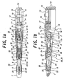
- FIG. 1a is a plan view showing a movable finger for a prosthesis according to an embodiment of the invention
- FIG. 1b is a vertical sectional view of the movable finger for a prosthesis of the embodiment.
- the movable finger for a prosthesis of the embodiment is used as at least one of a plurality of fingers of an upper extremity prosthesis as a prosthesis, and includes: a base 1 disposed between the back and the palm of a not shown hand; a first intermediate portion 3 having a rear end swingably connected to the tip of the base 1 through a first support shaft 2; a second intermediate portion 5 having a rear end swingably connected to the tip of the first intermediate tip 3 through a second support shaft 4; and a fingertip 7 having a rear end swingably connected to the tip of the second intermediate portion 5 through a third support shaft 6.
- the movable finger of the embodiment includes an electric-motorized linear driving device 12 disposed in the base 1 to serve as an actuator for pulling one end of each of two first wires 11 as first thin string members.
- the electric-motorized linear driving device 12 has an electric servo motor 13 incorporating a rotary encoder, a screw shaft 15 rotatably supported on the base 1 and coupled to be driven to an output shaft of the servo motor 13 through a gear combination 14 as a gear train, and a slider 16 engaged with the screw shaft 15 and slidably fitted to the base 1.
- One end of each of the two wires 11 is connected to the slider 16.
- two eccentric members 17 are disposed, which are supported by the first support shaft 2 so as to be rotated with respect to the base 1 and the first intermediate portion 3 and have winding portions 17a inconstant in distances from the first support shaft 2.
- Each of the first wires 11 is wound on each of pulleys 18 rotatably supported on the base 1, then passed through the finger inner side (lower side in FIG. 1b) of the first support shaft 2 to be wound on the winding portion 17a of each eccentric member 17.
- the other end of the first wire 11 is connected to the portion of the eccentric member 17 on a side, where the winding portion 17a is separated greatly from the first support shaft 2 (in the rotational position of the eccentric member 17 where the movable finger is straightened as shown in FIGS. 1a and 1b, the portion is located in a direction away from the base 1, i.e., in the left side of the first support shaft 2 in FIGS. 1a and 1b).
- the above mentioned portion of each eccentric member 17 is connected to a pin 3a fixed to the portion of the first intermediate portion 3 closer to the tip than the first support shaft 2 through a first intermediate portion pulling spring 19 and a connecting wire 20.
- a first intermediate portion straightening spring 21 is inserted between the first intermediate portion 3 and the base 1, to always urge the first intermediate portion 3 to take a straightened posture with respect to the base 1 as shown in FIGS. a and 1b, thus constituting a first intermediate portion bending mechanism 22.
- a pulley 24 having a second wire 23 wound as a second thin string member is disposed in the first intermediate portion 3 so as to be moved in the longitudinal direction of the first intermediate portion 3 by being guided by an oblong hole 3b formed in the first intermediate portion 3 to be extended in the longitudinal direction thereof.
- One end of the second wire 23 is connected to a pin 1a fixed to the base 1, through a guiding hole of a first guiding pulley 25 supported by the first support shaft 2 so as not to be rotated with respect to the base 1, the guiding hole being located in a finger outer side (upper side in FIG. 1b) with respect to the first support shaft 2.
- the other end of the second wire 23 is connected to a pin 17b fixed to the portion of the eccentric member 17 on a side greatly separated from the first support shaft 2.
- a second intermediate portion straightening spring 29 is inserted to always urge the second intermediate portion 5 to take a straightened posture with respect to the first intermediate portion 3 as shown in FIGS. 1a and 1b, thus constituting a second intermediate portion bending mechanism 30.
- the other end of the fourth wire 32 is wound on the finger inner side (lower side in FIG. 1b) of a fourth guiding pulley 33, which is rotatably supported by the third support shaft 6, and connected to the portion of the fingertip 7 closer to the tip than the third support shaft 6.
- a fifth wire 34 as a fifth thin string member wound on the finger inner side (lower side in FIG. 1b) of the third guiding pulley 31 is connected to the pin 3a of the first intermediate portion 3.
- the other end of the fifth wire 34 is wound on the finger outer side (upper side in FIG. 1b) of the fourth guiding pulley 33 and connected to the portion of the fingertip 7 closer to the tip than the third support shaft 6.
- a fingertip straightening spring 35 is provided between the fingertip 7 and the second intermediate portion 5, to always urge the fingertip 7 to take a straightened posture with respect to the second intermediate portion 5 as shown in FIGS. 1a and 1b, thus constituting a fingertip bending mechanism 36.
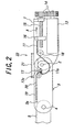
- FIG. 2 schematically shows the first intermediate portion bending mechanism 22 of the movable finger for a prosthesis of the embodiment.
- the first intermediate portion 3 having a portion closer to the tip than the first support shaft 2, the portion being connected to the portion 17c of the eccentric member 17 through the first intermediate portion pulling spring 19 and the connecting wire 20, is rotated toward the finger inner side (toward the palm of the hand) so as to take a bent posture with respect to the base 1 while opposing the first intermediate portion straightening spring 21 inserted between the first intermediate portion 3 and the base 1.
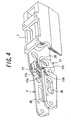
- FIGS. 4 and 5 are perspective views, each thereof showing only the base 1, the first intermediate portion 3, the eccentric member 17, and the first guiding pulley 25 in the movable finger of the embodiment, partially cutting away the base 1 and the first intermediate portion 3.
- FIG. 4 shows an initial straightened state of the first intermediate portion 3 with respect to the base 1 shown in FIGS. 1a, 1b and 2; and FIG. 5 a bent state of the first intermediate portion 3 with respect to the base 1 by rotation with the eccentric member 17, which is realized because the first intermediate portion 3 is not abutted on any objects and dose not receive resistance.
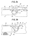
- the first intermediate portion 3 is rotated together with the eccentric member 17 with respect to the base 1. Accordingly, as shown in FIG. 3a, initially in the rotation, the first wire 11 wound on the portion (portion of a distance L1) of the winding portion 17a, which is not greatly separated from the first support shaft 2, is pulled, resulting in fast rotation of the first intermediate portion 3.
- first intermediate portion 3 is not rotated even by the increased torque, then by the rotation of the eccentric member 17 with respect to the base 1, only the second intermediate portion 5 and the fingertip 7 are rotated toward the finger inner side to a certain extent as described later with reference to FIG. 8b.
- a flat portion 17d is formed in the eccentric member 17, and an abutting portion 3c is protrudingly formed in the first intermediate portion 3.
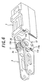
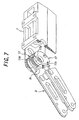
- FIGS. 6 and 7 are perspective views, each thereof showing only the base 1, the first intermediate portion 3, the eccentric member 17, and the first guiding pulley 25 in the movable finger of the embodiment, partially cutting away the base and the first intermediate portion 3.
- FIG. 6 shows a state shown in FIG. 3b that only the eccentric member 17 is rotated while the first intermediate portion 3 is not rotated; and
- FIG. 7 a bent state of the first intermediate portion 3 with respect to the base 1, which is set by abutting the flat portion 17d of the eccentric member 17 on the abutting portion 3c of the first intermediate portion 3 and forcibly rotating the first intermediate portion 3 by the eccentric member 17.
- FIG. 8a schematically shows the second intermediate portion bending mechanism 30 and the fingertip bending mechanism 36 of the movable finger for a prosthesis of the embodiment in a state where the second intermediate portion 5 is straightened with respect to the first intermediate portion 3, and the fingertip 7 is straightened with respect to the second intermediate portion 5;
- FIG. 8b schematically shows the second intermediate portion bending mechanism 30 and the fingertip bending mechanism 36 in a state where the second intermediate portion 5 is rotated to be bent with respect to the first intermediate portion 3, and the fingertip 7 is rotated to be bent with respect to the second intermediate portion 5.
- the first intermediate portion 3 is rotated toward the finger outer side so as to take a straightened posture with respect to the base 1 as shown in FIGS. 1a and 1b and FIG. 4.
- the first intermediate portion pulling spring 19 which is inserted between the pin 3a in the portion of the first intermediate portion 3 closer to the tip than the first support shaft 2 and the portion 17c of the eccentric member 17 on the side, where the winding portion 17a is greatly separated from the first support shaft 2, pulls the portion 17c of the eccentric member 17, and the eccentric member 17 is rotated with respect to the base 1 such that the portion 17c can be rotated toward the finger outer side to return to the original position thereof.
- the swinging of the first intermediate portion 3 with respect to the base 1 disposed between the back and the palm of the hand, the swinging of the second intermediate portion 5 with respect to the first intermediate portion 3, and the swinging of the fingertip 7 with respect to the second intermediate portion 5 are carried out in synchronization with one another, by the bending mechanism constructed to be slim and compact so as to be within the size of a human finger by using the wires.
- the finger can be bent and straightened.
- the rotational torque of the first intermediate portion 3 is automatically increased by the eccentric member 17, making it possible to firmly grip the object.
- the first intermediate portion 3 is not rotated at all or slightly rotated to stop due to resistance, only the second intermediate portion 5 and the fingertip 7 are continuously rotated to set the entire finger around the object.
- the object can be firmly gripped by the entire finger, being assisted by an action of increasing force by the pulley 24 of the first intermediate portion 3.
- FIG. 9 schematically shows a modified example of the movable finger for a prosthesis of the foregoing embodiment.
- one end of the second wire 23 of the second intermediate portion bending mechanism 30 is connected to a pin 3d fixed to the first intermediate portion 3 in place of the eccentric member 17.
- it is not allowed to rotate only the second intermediate portion 5 and the fingertip 7 toward the finger inner side.
- the first intermediate portion 3 is rotated to a certain extent, the second intermediate portion 5 and the fingertip 7 can be rotated in synchronization therewith, the entire finger is set around the object, and thus the object can be firmly gripped, being assisted by the action of increasing force by the pulley 24 of the first intermediate portion 3.
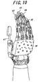
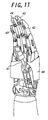
- FIGS. 10 and 11 are perspective views, each thereof showing an example of an upper extremity prosthesis or a prosthetic hand, to which the movable finger of the embodiment is applied, when seen from the back side or the palm side of the hand.
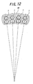
- four fingers excluding a thumb 41, i.e., a forefinger 42, a middle finger 43, a ring finger 44 and a little finger 45, are set as movable fingers of the embodiment, and the bases 1 of the movable fingers are housed in a sleeve 46 of a square-cylindrical section, which is slightly curved to have a center of curvature in the palm side of the hand and forms the back and the palm portions of the upper extremity prosthesis, by respectively having spaces around and being arranged to match the curved shapes of the back and the palm portions of the hand, as shown in FIG. 12.
- respective bending mechanisms are omitted.
- FIGS. 13a and 13b show a method of attaching the base 1 to the sleeve 46.
- attaching holes 47a to the sleeve 46 are bored in the center of a spring plate 47
- attaching holes 47b to the base 1 are bored in both sides of the spring plate 47.
- the spring plate 47 is attached to the sleeve 46 through the attaching holes 47a in the center of the spring plate 47
- the spring plate 47 is attached to the base through the attaching holes 47b in both sides of the spring plate 47.
- the thumb 41 of the upper extremity prosthesis of the applied example is provided with a base swingably supported by a support shaft extended roughly in parallel to the bases 1 of the other fingers 42 to 45, and a fingertip swingably supported on the base.
- the base is swung around the support shaft by a not-shown swing driving device provided in the sleeve 46 and driven by a not-shown normal electric servo motor.
- the fingertip is swung in directions toward and away from the other fingers 42 to 45 by a not-shown wire pulled by a linear driving device similar to the above-described electric-motorized linear driving device 12, and a not-shown spring provided in the base. Accordingly, the thumb 41 can function as a movable finger.
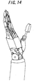
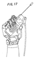
- each movable finger by properly operating each movable finger from the thumb 41 to the little finger 45, it is possible to achieve various states, e.g., a hand-open state shown in FIG. 14, a state in smoking cigarette or the like shown in FIG. 15, a pen-holding state shown in FIG. 16, a portable telephone holding state shown in FIG. 17.
- various states e.g., a hand-open state shown in FIG. 14, a state in smoking cigarette or the like shown in FIG. 15, a pen-holding state shown in FIG. 16, a portable telephone holding state shown in FIG. 17.
- the bending mechanisms are also omitted.
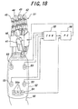
- FIG. 18 illustrates the constitution of a movable finger controller, which is suitably used for integral control of the five movable fingers from the thumb 41 to the little finger 45 of the upper extremity prosthesis 51 of the foregoing applied example.
- the controller of the embodiment includes: electrodes 53 as sensors provided in a plurality of places around a cylindrical holder 52, which is connected to the wrist of the upper extremity prosthesis 51 to put the upper extremity prosthesis 51 on a human arm 50 of no hand, so as to be brought into close contact with the skin of the arm 50 inserted into the holder 52, the electrodes 53 being adapted to detect a myoelectric signal flowing in the arm 50 by consciousness of the human with the arm 50 wearing the holder 52 to move a plurality of fingers; a touch type switch 54 as an operation mode changing means, having a plurality of touch panels 54a provided on the holder 52 to enable the human wearing the upper extremity prosthesis 51 to operate the plurality of touch panels 54a by the other hand or the like; known evolvable hardware
- the EHW 55 receives the myoelectric signals, learns the combination pattern of the myoelectric signals based on a genetic algorithm, and outputs an operation command signal according to the combination pattern.
- the PC 56 receives the operation command signal from the EHW 55, and a changing signal from the touch type switch 54 operated by the human, and carries out the feedback-control of the operation of the respective servo motors of the five movable fingers of the upper extremity prosthesis 51 based on the received signals and a program pregiven according to the combination of these signals.
- the controller of the embodiment only by the consciousness of the human wearing the upper extremity prosthesis 51 to move the fingers, the five movable fingers of the upper extremity prosthesis 51 can be respectively operated.
- plural kinds of operations such as object gripping, hand opening, pointing, for example like those shown in FIGS. 14 to 17, can be carried out by the upper extremity prosthesis 51.
- the programmable logic device automatically changes the combination of logical circuits based on the genetic algorithm, and learns adaptability between the combination pattern of the myoelectric signals and the operational state of each movable finger in such a way as to receive an input of adaptability determination from the human wearing the upper extremity prosthesis 51, and output an operation command signal according to the combination pattern of the myoelectric signals outputted from the plurality of electrodes 53.
- the controller can learn the combination pattern of the signals within a very short time so as to cause the upper extremity prosthesis 51 to carry out a desired operation.
- a program having a plurality of operation modes for one combination pattern can be beforehand provided to the PC 56.
- an operation mode to be currently used can be changed among a plurality of operation modes, e.g., the operation mode of a plurality of fingers when a portable telephone set is held, the operation mode of a plurality of fingers when a pencil is held, and so on, with respect to e.g. a combination pattern for holding an object.
- the plurality of movable fingers can carry out time-sequential operations, such as sequential bending of fingers.
- the movable finger of the invention may be used for all, or two or three of the fingers of the upper extremity prosthesis.
- the movable finger of the invention can be used for a lower extremity prosthesis, if necessary.
- the first intermediate portion bending mechanism of the movable finger of the invention may be provided with a pulley having a winding portion of a constant distance from the first support shaft, instead of the eccentric member. Even in such a case, the foregoing operations and effects excluding the torque increase of the eccentric member can be provided.
- the actuator of the movable finger of the invention may be a hydraulic cylinder or a pneumatic cylinder operated by a pressure supplied from a pressure source such as an electric pump and an accumulator.
- some of the first to fifth thin string members of the movable finger of the invention may be thread-like substances made of, e.g., carbon fibers or the like, instead of metal wires, as long as they have limited elongation, but good flexibility and sufficient durability.
- the sensor in the movable finger controller of the invention may be one directly adhered to the arm or the other part of the human wearing the prosthesis, and such a sensor may be adapted to detect a signal other than myoelectric one, e.g., the specific movement of the arm.
- the operation mode changing means may be one to change an operation mode not by the foregoing touch type switch but by a normal push type or a slide type switch, or a voice input.
- control of the movable finger of the invention may be carried out by omitting the foregoing sensor and the programmable logic device and entering operation changing from the operation changing switch directly operated or operated by a voice input or the like to the normal programmable controller (PC).
- PC normal programmable controller
- the bending operations and the straitening operations of the movable fingers may be carried out by being switched, separately by a plurality of changing switches corresponding to the plurality of movable fingers, or together by one switch of plural circuits and plural contacts assembling the functions of the changing switches.
- the present invention provides an upper extremity prosthesis capable of carrying out complex operations, and enables the upper extremity prosthesis to carry out complex operations easily.
Landscapes
- Health & Medical Sciences (AREA)
- Engineering & Computer Science (AREA)
- Transplantation (AREA)
- Orthopedic Medicine & Surgery (AREA)
- Life Sciences & Earth Sciences (AREA)
- Public Health (AREA)
- Heart & Thoracic Surgery (AREA)
- Vascular Medicine (AREA)
- Oral & Maxillofacial Surgery (AREA)
- Animal Behavior & Ethology (AREA)
- General Health & Medical Sciences (AREA)
- Biomedical Technology (AREA)
- Veterinary Medicine (AREA)
- Cardiology (AREA)
- Robotics (AREA)
- Mechanical Engineering (AREA)
- Prostheses (AREA)
- Manipulator (AREA)
- Gloves (AREA)
Claims (3)
- Beweglicher Finger für mindestens einen einer Vielzahl von Fingern einer Prothese, der aufweist:worin ein Betätigungselement (12) für das Ziehen eines Endes eines ersten dünnen Schnurelementes (11) in der Basis (1) angeordnet ist, dadurch gekennzeichnet, daß ein exzentrisches Element (17) oder anstelle des exzentrischen Elementes (17) eine Rolle mit einem Wickelabschnitt mit einem konstanten Abstand von der ersten Trägerwelle (2) in einem verbundenen Abschnitt zwischen der Basis (1) und dem ersten Zwischenabschnitt (3) angeordnet ist, wobei das exzentrische Element oder Rolle (17) durch die erste Trägerwelle (2) so getragen wird, daß es mit Bezugnahme auf die Basis (1) und den ersten Zwischenabschnitt (3) drehbar ist und einen Wickelabschnitt (17a) mit einem nicht konstanten Abstand von der ersten Trägerwelle (2) aufweist, wobei das erste dünne Schnurelement (11) durch eine Fingerinnenseite der ersten Trägerwelle (2) geführt und auf den Wickelabschnitt (17a) des exzentrischen Elementes (17) gewickelt wird, wobei das andere Ende des ersten dünnen Schnurelementes (11) mit einem Abschnitt des exzentrischen Elementes (17) verbunden wird, wobei das andere Ende des ersten dünnen Schnurelementes (11) mit einem Abschnitt des exzentrischen Elementes oder Rolle (17) auf einer Seite verbunden wird, wo der Wickelabschnitt (17a) in starkem Maß von der ersten Trägerwelle (2) getrennt ist, wobei der Abschnitt des exzentrischen Elementes (17) mit einem Abschnitt des ersten Zwischenabschnittes (3) näher an einem äußersten Ende des ersten Zwischenabschnittes (3) als die erste Trägerwelle (2) mittels einer ersten Zwischenabschnittszugfeder (19) verbunden wird, und wobei eine erste Zwischenabschnittsrichtfeder (21) zwischen dem ersten Zwischenabschnitt (3) und der Basis (1) eingesetzt wird, um den ersten Zwischenabschnitt (3) immer zu zwingen, eine ausgerichtete Haltung mit Bezugnahme auf die Basis (1) einzunehmen, wodurch ein erster Zwischenabschnittsbiegemechanismus (22) gebildet wird;eine Basis (1), die zwischen einem Handrücken und einem Handteller oder zwischen einem Spann und einer Sohle eines Fußes angeordnet wird;einen ersten Zwischenabschnitt (3) mit einem hinteren Ende, das schwenkbar mit einem äußersten Ende der Basis (1) mittels einer ersten Trägerwelle (2) verbunden ist;einen zweiten Zwischenabschnitt (5) mit einem hinteren Ende, das schwenkbar mit einem äußersten Ende des ersten Zwischenabschnittes (3) mittels einer zweiten Trägerwelle (4) verbunden ist; undeine Fingerspitze (7) mit einem hinteren Ende, das schwenkbar mit einem äußersten Ende des zweiten Zwischenabschnittes (5) mittels einer dritten Trägerwelle (6) verbunden ist,
eine Rolle (24), die mit einem zweiten dünnen Schnurelement (23) umwickelt wird, angeordnet im ersten Zwischenabschnitt (3), um so in einer Längsrichtung davon beweglich zu sein, wobei ein Ende des zweiten dünnen Schnurelementes (23) mit der Basis (1) mittels einer Fingeraußenseite der ersten Trägerwelle (2) verbunden wird, wobei das andere Ende des zweiten dünnen Schnurelementes (23) mit dem Abschnitt des exzentrischen Elementes (17) auf einer Seite verbunden wird, die in starkem Maß von der ersten Trägerwelle getrennt ist, oder mit dem ersten Zwischenabschnitt (3) anstelle des exzentrischen Elementes (17) verbunden wird, wobei ein Ende eines dritten dünnen Schnurelementes (27) - das andere Ende davon ist dabei mit einer Trägerwelle der Rolle (24) verbunden - mittels der Fingerinnenseite der zweiten Trägerwelle (4) mit einem Abschnitt des zweiten Zwischenabschnittes (5) näher an einem äußersten Ende davon als die zweite Trägerwelle (4) verbunden wird, und wobei eine zweite Zwischenabschnittsrichtfeder (29) zwischen dem zweiten Zwischenabschnitt (5) und dem ersten Zwischenabschnitt (3) eingesetzt wird, um den zweiten Zwischenabschnitt (5) immer zu zwingen, eine ausgerichtete Haltung mit Bezugnahme auf den ersten Zwischenabschnitt (3) einzunehmen, wodurch ein zweiter Zwischenabschnittsbiegemechanismus (30) gebildet wird; und
wobei ein Ende eines vierten dünnen Schnurelementes (32) - das andere Ende davon wird dabei mittels einer Fingeraußenseite der zweiten Trägerwelle (4) mit dem Abschnitt des ersten Zwischenabschnittes (3) verbunden, der näher an dessen hinteren Ende ist als die zweite Trägerwelle (4) - mittels einer Fingerinnenseite einer dritten Trägerwelle (6) mit einem Abschnitt der Fingerspitze (7) verbunden wird, der näher an einem äußersten Ende der Fingerspitze (7) als die dritte Trägerwelle (6) ist, und
wobei ein Ende eines fünften dünnen Schnurelementes (34) - das andere Ende davon wird dabei mittels einer Fingerinnenseite der zweiten Trägerwelle (4) mit dem Abschnitt des ersten Zwischenabschnittes (3) verbunden, der näher an dessen hinteren Ende ist als die zweite Trägerwelle (4) - mittels einer Fingeraußenseite der dritten Trägerwelle (6) mit einem Abschnitt der Fingerspitze (7) verbunden wird, die näher am äußeren Ende davon ist als die dritte Trägerwelle (6), wodurch ein Fingerspitzenbiegemechanismus (36) gebildet wird,
wobei anstelle des oder zusätzlich zum fünften dünnen Schnurelement (34) eine Fingerspitzenrichtfeder (35) zwischen der Fingerspitze (7) und dem zweiten Zwischenabschnitt (5) eingesetzt wird, um die Fingerspitze (7) immer zu zwingen, eine ausgerichtete Haltung mit Bezugnahme auf den zweiten Zwischenabschnitt (5) einzunehmen. - Prothese der oberen Extremität bei Verwendung eines beweglichen Fingers (42, 43, 44, 45) für eine Prothese, die im Anspruch 1 spezifiziert wird, die eines von Handrücken und Handteller aufweist;
worin die Basen (1) der beweglichen Finger (42, 43, 44, 45) für eine Prothese, die für eine Vielzahl von Fingern ausschließlich eines Daumens (41) verwendet werden, am Handrücken oder Handteller in einer gebogenen Anordnung befestigt werden, um einen Krümmungsmittelpunkt in einer Handtellerseite zu haben. - Prothese der oberen Extremität nach Anspruch 2, bei der die Basen (1) am Handrücken oder Handteller in der gebogenen Anordnung befestigt werden, damit sie elastisch geschwenkt werden können.
Applications Claiming Priority (3)
| Application Number | Priority Date | Filing Date | Title |
|---|---|---|---|
| JP11139150A JP3086452B1 (ja) | 1999-05-19 | 1999-05-19 | 義肢用可動指、その可動指を用いた義手、およびその可動指用制御装置 |
| JP13915099 | 1999-05-19 | ||
| PCT/JP2000/003219 WO2000071060A1 (en) | 1999-05-19 | 2000-05-19 | Movable finger for prostheses, upper extremity prostheses using this movable finger, and movable finger controller |
Publications (3)
| Publication Number | Publication Date |
|---|---|
| EP1195151A1 EP1195151A1 (de) | 2002-04-10 |
| EP1195151A4 EP1195151A4 (de) | 2003-04-02 |
| EP1195151B1 true EP1195151B1 (de) | 2005-10-12 |
Family
ID=15238738
Family Applications (1)
| Application Number | Title | Priority Date | Filing Date |
|---|---|---|---|
| EP00929803A Expired - Lifetime EP1195151B1 (de) | 1999-05-19 | 2000-05-19 | Beweglicher finger für eine prothese und finger für eine prothese der oberen extremität |
Country Status (8)
| Country | Link |
|---|---|
| US (1) | US6896704B1 (de) |
| EP (1) | EP1195151B1 (de) |
| JP (1) | JP3086452B1 (de) |
| AT (1) | ATE306234T1 (de) |
| CA (1) | CA2371919C (de) |
| DE (1) | DE60023142T2 (de) |
| HK (1) | HK1043299B (de) |
| WO (1) | WO2000071060A1 (de) |
Cited By (1)
| Publication number | Priority date | Publication date | Assignee | Title |
|---|---|---|---|---|
| DE102008056520A1 (de) * | 2008-11-08 | 2010-06-02 | Schulz, Stefan | Fingerelement |
Families Citing this family (131)
| Publication number | Priority date | Publication date | Assignee | Title |
|---|---|---|---|---|
| JP4545331B2 (ja) * | 2000-04-04 | 2010-09-15 | 本田技研工業株式会社 | 多指ハンド装置 |
| KR100802429B1 (ko) * | 2000-12-06 | 2008-02-13 | 혼다 기켄 고교 가부시키가이샤 | 다지 핸드 장치 |
| SE0102832D0 (sv) * | 2001-08-27 | 2001-08-27 | Bergomed Ab | Anordning vid en mellanhandsprotes |
| JP3793785B2 (ja) * | 2001-08-31 | 2006-07-05 | 広島県 | 多指可動ロボットハンド及びその把持制御方法 |
| GB2386886A (en) * | 2002-03-25 | 2003-10-01 | Shadow Robot Company Ltd | Humanoid type robotic hand |
| KR100511202B1 (ko) * | 2002-11-26 | 2005-08-31 | 한국과학기술원 | 케이블 메카니즘을 이용한 로봇 그리퍼 |
| JP2004180817A (ja) * | 2002-12-02 | 2004-07-02 | National Institute Of Advanced Industrial & Technology | 生体信号を利用した作業支援マニピュレータシステム |
| US8074559B2 (en) | 2007-02-06 | 2011-12-13 | Deka Products Limited Partnership | Dynamic support apparatus and system |
| US8956421B2 (en) | 2007-02-06 | 2015-02-17 | Deka Products Limited Partnership | Dynamic support apparatus and system |
| US7516678B2 (en) | 2005-03-10 | 2009-04-14 | Motorola, Inc. | Model hand for electromagnetic testing |
| JP4365341B2 (ja) * | 2005-03-31 | 2009-11-18 | 独立行政法人科学技術振興機構 | ロボットハンド |
| DE102005061266A1 (de) * | 2005-12-20 | 2007-08-16 | Otto Bock Healthcare Ip Gmbh & Co. Kg | Handprothese sowie Kraftübertragungseinrichtung |
| DE102005061312A1 (de) * | 2005-12-20 | 2007-08-16 | Otto Bock Healthcare Ip Gmbh & Co. Kg | Handprothese |
| DE102005061265A1 (de) | 2005-12-20 | 2007-06-21 | Otto Bock Healthcare Ip Gmbh & Co. Kg | Fingerprothese sowie Handprothese |
| DE102005061313A1 (de) * | 2005-12-20 | 2007-08-16 | Otto Bock Healthcare Ip Gmbh & Co. Kg | Handprothese |
| US20070198098A1 (en) * | 2006-02-17 | 2007-08-23 | Roston Gerald P | Fluid-powered prosthetic apparatus |
| ES2291112B1 (es) * | 2006-03-03 | 2008-12-16 | Corporacion Sanitaria Parc Tauli | Instrumento quirurgico para cirugia endoscopica. |
| JP4355781B2 (ja) * | 2006-07-12 | 2009-11-04 | 国立大学法人東京工業大学 | 把持装置 |
| JP5224227B2 (ja) * | 2006-07-16 | 2013-07-03 | 浩史 横井 | 全指可動型義手 |
| WO2008030419A2 (en) * | 2006-09-05 | 2008-03-13 | Mark Hunter | A modular mechanical device resembling a human arm and hand |
| DE102007005858A1 (de) * | 2007-02-01 | 2008-08-14 | Otto Bock Healthcare Products Gmbh | Prothesenfinger |
| US8979943B2 (en) | 2007-02-06 | 2015-03-17 | Deka Products Limited Partnership | Arm prosthetic device |
| US8870970B2 (en) * | 2007-02-06 | 2014-10-28 | Deka Products Limited Partnership | Dynamic support apparatus |
| WO2008098059A2 (en) * | 2007-02-06 | 2008-08-14 | Deka Integrated Solutions Corp. | Method and apparatus for control of a prosthetic |
| US8864845B2 (en) * | 2007-02-06 | 2014-10-21 | DEKA Limited Partnership | System for control of a prosthetic device |
| US8449624B2 (en) * | 2007-02-06 | 2013-05-28 | Deka Products Limited Partnership | Arm prosthetic device |
| US10426638B2 (en) | 2007-02-06 | 2019-10-01 | Deka Products Limited Partnership | Arm prosthetic device |
| EP2114315B1 (de) * | 2007-02-06 | 2016-05-18 | DEKA Products Limited Partnership | Armprothesenvorrichtung |
| US11779476B2 (en) | 2007-02-06 | 2023-10-10 | Deka Products Limited Partnership | Arm prosthetic device |
| US9381099B2 (en) | 2007-02-06 | 2016-07-05 | Deka Products Limited Partnership | Arm prosthetic device |
| US9114030B2 (en) | 2007-02-06 | 2015-08-25 | Deka Products Limited Partnership | System for control of a prosthetic device |
| DE102007013660A1 (de) * | 2007-03-19 | 2008-09-25 | Genesis Adaptive Systeme Deutschland Gmbh | Exoprothese |
| JP5301930B2 (ja) | 2008-09-11 | 2013-09-25 | パナソニック株式会社 | 指用動作補助装置 |
| KR100895872B1 (ko) * | 2008-10-31 | 2009-04-30 | 이승호 | 전자 의수 |
| US8060250B2 (en) * | 2008-12-15 | 2011-11-15 | GM Global Technology Operations LLC | Joint-space impedance control for tendon-driven manipulators |
| US8052185B2 (en) * | 2009-04-09 | 2011-11-08 | Disney Enterprises, Inc. | Robot hand with humanoid fingers |
| EP2419057B1 (de) * | 2009-04-13 | 2014-10-01 | DEKA Products Limited Partnership | System und gerät zur orientierungskontrolle |
| JP5500921B2 (ja) * | 2009-09-10 | 2014-05-21 | 本田技研工業株式会社 | 多指ハンド装置 |
| WO2011001136A2 (en) * | 2009-07-02 | 2011-01-06 | Rslsteeper Group Limited | Prosthetic apparatus |
| GB2496335A (en) * | 2009-07-22 | 2013-05-08 | Shadow Robot Company Ltd | Finger digit for robotic hand |
| US9265625B2 (en) | 2009-08-20 | 2016-02-23 | Vanderbilt University | Jointed mechanical devices |
| EP2467101B1 (de) * | 2009-08-20 | 2016-04-06 | Vanderbilt University | Steuersystem für gelenkige mechanische vorrichtungen |
| JP5341681B2 (ja) * | 2009-09-01 | 2013-11-13 | 本田技研工業株式会社 | 義指装置 |
| US8467903B2 (en) * | 2009-09-22 | 2013-06-18 | GM Global Technology Operations LLC | Tendon driven finger actuation system |
| EP2480173B1 (de) | 2009-09-22 | 2016-11-23 | Memic Innovative Surgery Ltd. | Mechanischem finger |
| EP2512758B1 (de) | 2009-12-14 | 2017-09-13 | HDT Expeditionary Systems, Inc. | Einzelmotor-fingermechanismus |
| RU2427349C1 (ru) * | 2010-02-16 | 2011-08-27 | Федеральное государственное учреждение "Санкт-Петербургский научно-практический центр медико-социальной экспертизы, протезирования и реабилитации инвалидов им. Г.А. Альбрехта Федерального агентства по здравоохранению и социальному развитию" (ФГУ "СПбНЦЭР им. Альбрехта Росздрава") | Многофункциональный активный протез руки |
| WO2011118646A1 (ja) | 2010-03-24 | 2011-09-29 | 株式会社安川電機 | ロボットハンド及びロボット装置 |
| US9844447B2 (en) | 2010-04-09 | 2017-12-19 | Deka Products Limited Partnership | System and apparatus for robotic device and methods of using thereof |
| CN101829993B (zh) * | 2010-04-30 | 2012-05-02 | 清华大学 | 齿条曲柄滑块式并联耦合欠驱动机器人手指装置 |
| WO2012039479A1 (ja) * | 2010-09-24 | 2012-03-29 | 国立大学法人岐阜大学 | 人間型電動ハンド |
| US8776632B2 (en) * | 2011-08-19 | 2014-07-15 | GM Global Technology Operations LLC | Low-stroke actuation for a serial robot |
| JP5767563B2 (ja) * | 2011-11-02 | 2015-08-19 | 本田技研工業株式会社 | 多指型ハンド装置 |
| CN102528814A (zh) * | 2012-02-15 | 2012-07-04 | 清华大学 | 拨杆滑槽式间接欠驱动机器人手指装置 |
| US8573663B1 (en) * | 2012-04-30 | 2013-11-05 | Precision Machinery Research & Development Center | Finger-gesticulation hand device |
| RU2506931C2 (ru) * | 2012-05-03 | 2014-02-20 | ФЕДЕРАЛЬНОЕ ГОСУДАРСТВЕННОЕ БЮДЖЕТНОЕ УЧРЕЖДЕНИЕ "САНКТ-ПЕТЕРБУРГСКИЙ НАУЧНО-ПРАКТИЧЕСКИЙ ЦЕНТР МЕДИКО-СОЦИАЛЬНОЙ ЭКСПЕРТИЗЫ, ПРОТЕЗИРОВАНИЯ И РЕАБИЛИТАЦИИ ИНВАЛИДОВ ИМ. Г.А. АЛЬБРЕХТА ФЕДЕРАЛЬНОГО МЕДИКО-БИОЛОГИЧЕСКОГО АГЕНТСТВА" (ФГБУ СПб НЦЭПР им. Г.А. Альбрехта ФМБА России) | Протез кисти |
| US8922150B1 (en) | 2012-07-18 | 2014-12-30 | The Johns Hopkins University | Differential serial driver |
| CN102825610A (zh) * | 2012-08-15 | 2012-12-19 | 清华大学 | 双电机协同复合抓取机器人手指装置 |
| CN102814820A (zh) * | 2012-08-24 | 2012-12-12 | 清华大学 | 锥齿轮系双电机协同复合抓取机器人手指装置 |
| CN102806561A (zh) * | 2012-08-27 | 2012-12-05 | 清华大学 | 分轴式双电机协同复合抓取机器人手指装置 |
| CN102873687B (zh) * | 2012-09-06 | 2014-12-24 | 清华大学 | 分布式多电机协同复合抓取机器人手指装置 |
| US10132336B1 (en) | 2013-04-22 | 2018-11-20 | Vecna Technologies, Inc. | Actuator for rotating members |
| JP2014073222A (ja) * | 2012-10-04 | 2014-04-24 | Sony Corp | 運動補助装置及び運動補助方法 |
| ITPI20130004A1 (it) * | 2013-01-16 | 2014-07-17 | Machinale S R L Fab | Struttura protesica per amputazione mano |
| DE102013007539A1 (de) * | 2013-05-03 | 2014-11-06 | Otto Bock Healthcare Products Gmbh | Künstlicher Finger |
| US9440361B1 (en) * | 2013-06-28 | 2016-09-13 | Daniel Theobald | Activation element and method |
| GB201403265D0 (en) | 2014-02-25 | 2014-04-09 | Touch Emas Ltd | Prosthetic digit for use with touchscreen devices |
| JP6284438B2 (ja) * | 2014-06-12 | 2018-02-28 | オリンパス株式会社 | マニピュレータ |
| CN104139811B (zh) * | 2014-07-18 | 2016-04-13 | 华中科技大学 | 一种欠驱动的仿生四足机器人 |
| JP6479376B2 (ja) * | 2014-09-09 | 2019-03-06 | 満 入江 | 可動義手 |
| US9492928B2 (en) | 2014-11-05 | 2016-11-15 | Toyota Motor Engineering & Manufacturing North America, Inc. | Interconnected phalanges for robotic gripping |
| CN104665962B (zh) * | 2015-02-05 | 2017-04-05 | 华南理工大学 | 可穿戴式功能增强机器手系统及其辅助手指和控制方法 |
| GB2537899B (en) | 2015-04-30 | 2018-02-21 | Hy5Pro As | Control of digits for artificial hand |
| WO2016182421A1 (es) * | 2015-05-08 | 2016-11-17 | Amezcua Peregrina Miguel | Mano protésica multiarticulada motorizada y controlable completamente por el usuario |
| WO2016194067A1 (ja) * | 2015-05-29 | 2016-12-08 | オリンパス株式会社 | 把持機構および把持具 |
| CA2934405A1 (en) | 2015-06-26 | 2016-12-26 | Nikolai Dechev | Custom fitted body powered prosthetic upper limb manufactured by 3d printing |
| KR101738098B1 (ko) * | 2015-07-30 | 2017-05-22 | 창명제어기술 (주) | 근전도 방식의 전동 의수 및 그 제어 장치 |
| ITUB20155328A1 (it) * | 2015-11-02 | 2017-05-02 | Univ Pisa | Mano robotica |
| CN106109066B (zh) * | 2015-11-18 | 2018-01-16 | 杭州若比邻机器人科技有限公司 | 假肢拇指的安装结构 |
| CN106038009B (zh) * | 2015-11-18 | 2018-02-06 | 杭州若比邻机器人科技有限公司 | 假肢手 |
| CN105382844B (zh) * | 2015-12-24 | 2017-03-22 | 佛山市天帆数控科技有限公司 | 一种基于时序控制的多自由度机械手 |
| WO2017115893A1 (ko) | 2015-12-31 | 2017-07-06 | 만드로 주식회사 | 전자 의수 |
| CN105583839A (zh) * | 2016-03-17 | 2016-05-18 | 清华大学 | 自复位开环柔性件耦合灵巧机器人手指装置 |
| CN105619440B (zh) * | 2016-03-17 | 2018-07-06 | 清华大学 | 开链柔性件平夹自适应机器人手指装置 |
| WO2017195246A1 (ja) | 2016-05-09 | 2017-11-16 | オリンパス株式会社 | 把持機構および把持具 |
| ITUA20163457A1 (it) | 2016-05-16 | 2017-11-16 | Univ Pisa | Mano artificiale |
| JPWO2017208320A1 (ja) * | 2016-05-31 | 2019-03-22 | オリンパス株式会社 | 把持機構および把持具 |
| WO2017212587A1 (ja) | 2016-06-08 | 2017-12-14 | オリンパス株式会社 | 把持機構および把持具 |
| CN105881530A (zh) * | 2016-06-12 | 2016-08-24 | 深圳博美德机器人股份有限公司 | 机械手 |
| CN106038007B (zh) * | 2016-07-04 | 2017-11-07 | 中国科学院深圳先进技术研究院 | 仿生假肢手 |
| FR3053618B1 (fr) * | 2016-07-05 | 2020-02-21 | Softbank Robotics Europe | Main destinee a equiper un robot a caractere humanoide |
| JP6872340B2 (ja) * | 2016-10-06 | 2021-05-19 | 満 入江 | 電動義手 |
| WO2018096689A1 (ja) | 2016-11-28 | 2018-05-31 | オリンパス株式会社 | 医療用処置具 |
| US11026816B2 (en) * | 2017-01-12 | 2021-06-08 | Deka Products Limited Partnership | Prosthetic device |
| US10464217B1 (en) * | 2017-09-29 | 2019-11-05 | Traptic, Inc. | Robotic gripper with driven belts |
| US10973660B2 (en) | 2017-12-15 | 2021-04-13 | Touch Bionics Limited | Powered prosthetic thumb |
| DE102017130082B4 (de) * | 2017-12-15 | 2019-07-04 | Ottobock Se & Co. Kgaa | Prothesenhand |
| CN108371575B (zh) * | 2018-01-23 | 2024-08-20 | 莆田学院 | 一种断指辅助抓取及敲击装置 |
| IT201800003961A1 (it) * | 2018-03-26 | 2019-09-26 | Fondazione St Italiano Tecnologia | Polso artificiale |
| CN109223259B (zh) * | 2018-08-30 | 2021-01-22 | 京东方科技集团股份有限公司 | 假肢 |
| GB2577499B (en) * | 2018-09-25 | 2020-11-18 | Covvi Ltd | A mechanical hand |
| GB201900046D0 (en) * | 2018-12-21 | 2019-02-13 | Be Bionic Llc | Linear actuator assembly, bionic digit and prosthetic hand |
| CN111376287B (zh) * | 2018-12-29 | 2021-10-29 | 深圳市优必选科技有限公司 | 机器人及其手指 |
| CN111376286B (zh) * | 2018-12-29 | 2021-10-29 | 深圳市优必选科技有限公司 | 手指驱动机构及灵巧手 |
| CN109822602B (zh) * | 2019-01-18 | 2021-11-26 | 湖南大学 | 一种手指间协同驱动机构 |
| CN109591038B (zh) * | 2019-01-22 | 2021-05-18 | 北京邮电大学 | 一种具有被动旋转关节的仿人灵巧手及其操作方法 |
| JP6713562B2 (ja) * | 2019-02-06 | 2020-06-24 | 社会福祉法人兵庫県社会福祉事業団 | 可動義手 |
| WO2020204843A2 (en) * | 2019-02-28 | 2020-10-08 | Boonyasurakul Boonyawee | Device for grasping an object and method for controlling the device |
| US10449677B1 (en) * | 2019-03-12 | 2019-10-22 | United Arab Emirates University | Robotic gripping assist |
| KR102251364B1 (ko) | 2019-03-28 | 2021-05-12 | 근로복지공단 | 근전 전동의수의 엄지기반 손동작 제어시스템 및 그 제어방법 |
| CN113853181A (zh) | 2019-04-10 | 2021-12-28 | 塔驰仿生有限公司 | 具有铰接连杆的假肢手指 |
| KR102247103B1 (ko) | 2019-05-30 | 2021-04-30 | 한양대학교 에리카산학협력단 | 관절 메커니즘 |
| CN110123420B (zh) * | 2019-06-01 | 2020-12-08 | 青岛大学附属医院 | 一种消化内镜微创手术刀装置 |
| CN110370305B (zh) * | 2019-07-22 | 2021-04-09 | 珠海格力智能装备有限公司 | 机械指及机械手 |
| US11564815B2 (en) | 2019-09-17 | 2023-01-31 | Victoria Hand Project | Upper arm prosthetic apparatus and systems |
| US12527672B2 (en) | 2019-09-18 | 2026-01-20 | Touch Bionics Limited | Prosthetic digits and actuators |
| US11931270B2 (en) | 2019-11-15 | 2024-03-19 | Touch Bionics Limited | Prosthetic digit actuator |
| JP7620566B2 (ja) * | 2019-11-27 | 2025-01-23 | 株式会社Preferred Networks | 複数の指を持つ機構及び装置 |
| CN111185929A (zh) * | 2020-01-13 | 2020-05-22 | 北京航空航天大学 | 一种基于柔索驱动的灵巧手手指结构 |
| KR102250605B1 (ko) * | 2020-03-02 | 2021-05-10 | 재단법인대구경북과학기술원 | 로봇 관절구조 및 이를 포함하는 로봇손 |
| CN111558203B (zh) * | 2020-03-25 | 2024-01-12 | 威海威高医疗系统有限公司 | 智能握力辅助手套 |
| CN111558204B (zh) * | 2020-03-25 | 2024-01-12 | 威海威高医疗系统有限公司 | 智能握力辅助手套导向器 |
| DE102020115098A1 (de) | 2020-06-05 | 2021-12-09 | Stefan Schulz | Spreizbare Handprothese |
| RU2759777C1 (ru) * | 2020-08-07 | 2021-11-17 | Общество с ограниченной ответственностью "МОТОРИКА" | Палец тягового протеза и устройство протеза кисти и протеза предплечья с такими пальцами |
| US11957606B2 (en) | 2020-10-29 | 2024-04-16 | Victoria Hand Project | Low-cost prosthetic apparatus, methods, kits, and systems with improved force transfer elements |
| US11325264B1 (en) * | 2020-11-12 | 2022-05-10 | Ubtech North America Research And Development Center Corp | Tendon-driven robotic hand |
| CN112518781B (zh) * | 2020-11-26 | 2022-04-26 | 杭州萤石软件有限公司 | 机械手及其机械手指 |
| JP7530854B2 (ja) * | 2021-03-24 | 2024-08-08 | 本田技研工業株式会社 | ロボットハンド |
| DE102021130657A1 (de) | 2021-11-23 | 2023-05-25 | Otto Bock Healthcare Products Gmbh | Orthopädietechnische Einrichtung |
| UA129918C2 (uk) * | 2022-03-18 | 2025-09-10 | Еспер Інк. | Механічний палець для штучної кисті та актуатор механічного пальця |
| CN115781731A (zh) * | 2022-11-25 | 2023-03-14 | 清华大学 | 仿人柔性灵巧手及其手指关节 |
Family Cites Families (11)
| Publication number | Priority date | Publication date | Assignee | Title |
|---|---|---|---|---|
| FR923480A (fr) * | 1946-03-08 | 1947-07-08 | Appareil de prothèse des membres supérieurs | |
| JPS53880B2 (de) | 1974-04-25 | 1978-01-12 | ||
| SU910410A2 (ru) * | 1979-10-08 | 1982-03-07 | Предприятие П/Я В-2331 | Захват манипул тора |
| SU1161377A2 (ru) * | 1983-08-29 | 1985-06-15 | Kucheryavyj Ivan | "зaxbat mahипуляtopa" |
| FR2557450B1 (fr) * | 1983-10-05 | 1986-05-02 | Monestier Jacques | Perfectionnements apportes aux protheses totales de main |
| SU1553381A1 (ru) * | 1988-05-16 | 1990-03-30 | Предприятие П/Я Г-4849 | Захватное устройство |
| JPH02145282A (ja) | 1988-11-25 | 1990-06-04 | Agency Of Ind Science & Technol | 人間類似型上肢機構 |
| GB8922368D0 (en) * | 1989-10-04 | 1989-11-22 | Steeper Hugh Ltd | Multifunction control of a prosthetic limb using syntactic analysis of the dynamic myoelectric signal patterns associated with the onset of muscle contraction |
| US5336269A (en) * | 1992-06-09 | 1994-08-09 | Liberty Mutual Insurance Co. | Method and apparatus for switching degrees of freedom in a prosthetic limb |
| US5413611A (en) | 1992-07-21 | 1995-05-09 | Mcp Services, Inc. | Computerized electronic prosthesis apparatus and method |
| GB9719635D0 (en) * | 1997-09-15 | 1997-11-19 | Univ London | Manipulator |
-
1999
- 1999-05-19 JP JP11139150A patent/JP3086452B1/ja not_active Expired - Lifetime
-
2000
- 2000-05-19 DE DE60023142T patent/DE60023142T2/de not_active Expired - Fee Related
- 2000-05-19 US US09/979,033 patent/US6896704B1/en not_active Expired - Lifetime
- 2000-05-19 AT AT00929803T patent/ATE306234T1/de not_active IP Right Cessation
- 2000-05-19 CA CA002371919A patent/CA2371919C/en not_active Expired - Lifetime
- 2000-05-19 WO PCT/JP2000/003219 patent/WO2000071060A1/ja not_active Ceased
- 2000-05-19 EP EP00929803A patent/EP1195151B1/de not_active Expired - Lifetime
- 2000-05-19 HK HK02104511.0A patent/HK1043299B/en not_active IP Right Cessation
Cited By (2)
| Publication number | Priority date | Publication date | Assignee | Title |
|---|---|---|---|---|
| DE102008056520A1 (de) * | 2008-11-08 | 2010-06-02 | Schulz, Stefan | Fingerelement |
| DE102008056520B4 (de) * | 2008-11-08 | 2017-10-19 | Stefan Schulz | Fingerelement |
Also Published As
| Publication number | Publication date |
|---|---|
| HK1043299A1 (en) | 2002-09-13 |
| EP1195151A1 (de) | 2002-04-10 |
| ATE306234T1 (de) | 2005-10-15 |
| CA2371919A1 (en) | 2000-11-30 |
| DE60023142T2 (de) | 2006-07-06 |
| EP1195151A4 (de) | 2003-04-02 |
| CA2371919C (en) | 2006-01-03 |
| HK1043299B (en) | 2006-01-20 |
| JP2000325375A (ja) | 2000-11-28 |
| JP3086452B1 (ja) | 2000-09-11 |
| US6896704B1 (en) | 2005-05-24 |
| DE60023142D1 (de) | 2006-02-23 |
| WO2000071060A1 (en) | 2000-11-30 |
Similar Documents
| Publication | Publication Date | Title |
|---|---|---|
| CA2371919C (en) | Movable finger for prostheses, upper extremity prostheses using this movable finger, and movable finger controller | |
| EP2467101B1 (de) | Steuersystem für gelenkige mechanische vorrichtungen | |
| US7296835B2 (en) | Robotic hand and arm apparatus | |
| US9730815B2 (en) | Control system for a grasping device | |
| JP5242409B2 (ja) | 義手 | |
| US10618182B2 (en) | Underactuated mechanical finger capable of linear motion with compensatory displacement, mechanical gripper and robot containing the same | |
| EP2653137A1 (de) | Kompakte multifunktionelle Handprothese | |
| WO2003051583A1 (en) | Multi-finger hand device | |
| EP3878609B1 (de) | Roboterhand | |
| EP3790513B1 (de) | Unterbetätigte handprothese | |
| KR20220144854A (ko) | 로봇 핸드 | |
| EP4370072A1 (de) | Künstliche hand | |
| US20250041079A1 (en) | Anatomical prosthesis with a mechanism for independent finger actuation | |
| JP2001104349A (ja) | 親指形状可変型義手 | |
| EP3790514B1 (de) | Fingerprothese | |
| WO2024155249A1 (en) | A control method for a robotic hand | |
| JP2023119277A (ja) | ロボットハンド装置及びロボットハンド動作方法 | |
| US10912662B2 (en) | Electrically driven artificial arm and method of use | |
| CN112494186B (zh) | 一种面向大拇指缺失人群的机械辅助抓取装置 | |
| JP2019076786A (ja) | 可動義手 | |
| KR102246500B1 (ko) | 부족 구동을 위한 슬라이더형 와이어 구동기 및 이를 구비한 장갑형 입는 로봇 | |
| CN119328796A (zh) | 灵巧手 | |
| JP2021130049A (ja) | 電動義手の指駆動ユニット |
Legal Events
| Date | Code | Title | Description |
|---|---|---|---|
| PUAI | Public reference made under article 153(3) epc to a published international application that has entered the european phase |
Free format text: ORIGINAL CODE: 0009012 |
|
| 17P | Request for examination filed |
Effective date: 20011214 |
|
| AK | Designated contracting states |
Kind code of ref document: A1 Designated state(s): AT BE CH CY DE DK ES FI FR GB GR IE IT LI LU MC NL PT SE |
|
| RIC1 | Information provided on ipc code assigned before grant |
Free format text: 7A 61F 2/56 A, 7A 61F 2/72 B, 7A 61F 2/58 B, 7B 25J 15/00 B, 7A 61F 2/42 B, 7A 61F 2/68 B |
|
| A4 | Supplementary search report drawn up and despatched |
Effective date: 20030212 |
|
| 17Q | First examination report despatched |
Effective date: 20031022 |
|
| GRAP | Despatch of communication of intention to grant a patent |
Free format text: ORIGINAL CODE: EPIDOSNIGR1 |
|
| RTI1 | Title (correction) |
Free format text: MOVABLE FINGER FOR PROSTHESES AND UPPER EXTREMITY PROSTHESES USING THIS MOVABLE FINGER |
|
| GRAS | Grant fee paid |
Free format text: ORIGINAL CODE: EPIDOSNIGR3 |
|
| GRAA | (expected) grant |
Free format text: ORIGINAL CODE: 0009210 |
|
| AK | Designated contracting states |
Kind code of ref document: B1 Designated state(s): AT BE CH CY DE DK ES FI FR GB GR IE IT LI LU MC NL PT SE |
|
| PG25 | Lapsed in a contracting state [announced via postgrant information from national office to epo] |
Ref country code: FI Free format text: LAPSE BECAUSE OF FAILURE TO SUBMIT A TRANSLATION OF THE DESCRIPTION OR TO PAY THE FEE WITHIN THE PRESCRIBED TIME-LIMIT Effective date: 20051012 Ref country code: BE Free format text: LAPSE BECAUSE OF FAILURE TO SUBMIT A TRANSLATION OF THE DESCRIPTION OR TO PAY THE FEE WITHIN THE PRESCRIBED TIME-LIMIT Effective date: 20051012 Ref country code: NL Free format text: LAPSE BECAUSE OF FAILURE TO SUBMIT A TRANSLATION OF THE DESCRIPTION OR TO PAY THE FEE WITHIN THE PRESCRIBED TIME-LIMIT Effective date: 20051012 Ref country code: AT Free format text: LAPSE BECAUSE OF FAILURE TO SUBMIT A TRANSLATION OF THE DESCRIPTION OR TO PAY THE FEE WITHIN THE PRESCRIBED TIME-LIMIT Effective date: 20051012 |
|
| REG | Reference to a national code |
Ref country code: GB Ref legal event code: FG4D |
|
| REG | Reference to a national code |
Ref country code: CH Ref legal event code: EP |
|
| REG | Reference to a national code |
Ref country code: IE Ref legal event code: FG4D |
|
| PG25 | Lapsed in a contracting state [announced via postgrant information from national office to epo] |
Ref country code: GR Free format text: LAPSE BECAUSE OF FAILURE TO SUBMIT A TRANSLATION OF THE DESCRIPTION OR TO PAY THE FEE WITHIN THE PRESCRIBED TIME-LIMIT Effective date: 20060112 Ref country code: DK Free format text: LAPSE BECAUSE OF FAILURE TO SUBMIT A TRANSLATION OF THE DESCRIPTION OR TO PAY THE FEE WITHIN THE PRESCRIBED TIME-LIMIT Effective date: 20060112 |
|
| REG | Reference to a national code |
Ref country code: HK Ref legal event code: GR Ref document number: 1043299 Country of ref document: HK |
|
| PG25 | Lapsed in a contracting state [announced via postgrant information from national office to epo] |
Ref country code: ES Free format text: LAPSE BECAUSE OF FAILURE TO SUBMIT A TRANSLATION OF THE DESCRIPTION OR TO PAY THE FEE WITHIN THE PRESCRIBED TIME-LIMIT Effective date: 20060123 |
|
| REG | Reference to a national code |
Ref country code: SE Ref legal event code: TRGR |
|
| REF | Corresponds to: |
Ref document number: 60023142 Country of ref document: DE Date of ref document: 20060223 Kind code of ref document: P |
|
| PG25 | Lapsed in a contracting state [announced via postgrant information from national office to epo] |
Ref country code: PT Free format text: LAPSE BECAUSE OF FAILURE TO SUBMIT A TRANSLATION OF THE DESCRIPTION OR TO PAY THE FEE WITHIN THE PRESCRIBED TIME-LIMIT Effective date: 20060313 |
|
| REG | Reference to a national code |
Ref country code: CH Ref legal event code: NV Representative=s name: RITSCHER & PARTNER AG |
|
| NLV1 | Nl: lapsed or annulled due to failure to fulfill the requirements of art. 29p and 29m of the patents act | ||
| PG25 | Lapsed in a contracting state [announced via postgrant information from national office to epo] |
Ref country code: IE Free format text: LAPSE BECAUSE OF NON-PAYMENT OF DUE FEES Effective date: 20060519 Ref country code: GB Free format text: LAPSE BECAUSE OF NON-PAYMENT OF DUE FEES Effective date: 20060519 |
|
| PG25 | Lapsed in a contracting state [announced via postgrant information from national office to epo] |
Ref country code: MC Free format text: LAPSE BECAUSE OF NON-PAYMENT OF DUE FEES Effective date: 20060531 |
|
| ET | Fr: translation filed | ||
| PLBE | No opposition filed within time limit |
Free format text: ORIGINAL CODE: 0009261 |
|
| STAA | Information on the status of an ep patent application or granted ep patent |
Free format text: STATUS: NO OPPOSITION FILED WITHIN TIME LIMIT |
|
| 26N | No opposition filed |
Effective date: 20060713 |
|
| GBPC | Gb: european patent ceased through non-payment of renewal fee |
Effective date: 20060519 |
|
| REG | Reference to a national code |
Ref country code: IE Ref legal event code: MM4A |
|
| PGFP | Annual fee paid to national office [announced via postgrant information from national office to epo] |
Ref country code: SE Payment date: 20070529 Year of fee payment: 8 |
|
| PGFP | Annual fee paid to national office [announced via postgrant information from national office to epo] |
Ref country code: IT Payment date: 20070528 Year of fee payment: 8 |
|
| REG | Reference to a national code |
Ref country code: CH Ref legal event code: PCAR Free format text: RITSCHER & PARTNER AG;RESIRAIN 1;8125 ZOLLIKERBERG (CH) |
|
| PGFP | Annual fee paid to national office [announced via postgrant information from national office to epo] |
Ref country code: FR Payment date: 20070525 Year of fee payment: 8 |
|
| PG25 | Lapsed in a contracting state [announced via postgrant information from national office to epo] |
Ref country code: LU Free format text: LAPSE BECAUSE OF NON-PAYMENT OF DUE FEES Effective date: 20060519 |
|
| PGFP | Annual fee paid to national office [announced via postgrant information from national office to epo] |
Ref country code: CH Payment date: 20080527 Year of fee payment: 9 Ref country code: DE Payment date: 20080522 Year of fee payment: 9 |
|
| PG25 | Lapsed in a contracting state [announced via postgrant information from national office to epo] |
Ref country code: CY Free format text: LAPSE BECAUSE OF FAILURE TO SUBMIT A TRANSLATION OF THE DESCRIPTION OR TO PAY THE FEE WITHIN THE PRESCRIBED TIME-LIMIT Effective date: 20051012 |
|
| REG | Reference to a national code |
Ref country code: FR Ref legal event code: ST Effective date: 20090119 |
|
| PG25 | Lapsed in a contracting state [announced via postgrant information from national office to epo] |
Ref country code: FR Free format text: LAPSE BECAUSE OF NON-PAYMENT OF DUE FEES Effective date: 20080602 |
|
| PG25 | Lapsed in a contracting state [announced via postgrant information from national office to epo] |
Ref country code: IT Free format text: LAPSE BECAUSE OF NON-PAYMENT OF DUE FEES Effective date: 20080519 |
|
| REG | Reference to a national code |
Ref country code: CH Ref legal event code: PL |
|
| PG25 | Lapsed in a contracting state [announced via postgrant information from national office to epo] |
Ref country code: CH Free format text: LAPSE BECAUSE OF NON-PAYMENT OF DUE FEES Effective date: 20090531 Ref country code: LI Free format text: LAPSE BECAUSE OF NON-PAYMENT OF DUE FEES Effective date: 20090531 |
|
| PG25 | Lapsed in a contracting state [announced via postgrant information from national office to epo] |
Ref country code: DE Free format text: LAPSE BECAUSE OF NON-PAYMENT OF DUE FEES Effective date: 20091201 |
|
| PG25 | Lapsed in a contracting state [announced via postgrant information from national office to epo] |
Ref country code: SE Free format text: LAPSE BECAUSE OF NON-PAYMENT OF DUE FEES Effective date: 20080520 |