EP1195268B1 - Dispositif pour graver des images et adaptateur correspondant pour maintenir la pièce à graver - Google Patents
Dispositif pour graver des images et adaptateur correspondant pour maintenir la pièce à graver Download PDFInfo
- Publication number
- EP1195268B1 EP1195268B1 EP01307784A EP01307784A EP1195268B1 EP 1195268 B1 EP1195268 B1 EP 1195268B1 EP 01307784 A EP01307784 A EP 01307784A EP 01307784 A EP01307784 A EP 01307784A EP 1195268 B1 EP1195268 B1 EP 1195268B1
- Authority
- EP
- European Patent Office
- Prior art keywords
- axis
- driver
- adaptor
- rectangular
- engraved
- Prior art date
- Legal status (The legal status is an assumption and is not a legal conclusion. Google has not performed a legal analysis and makes no representation as to the accuracy of the status listed.)
- Expired - Lifetime
Links
Images



Classifications
-
- B—PERFORMING OPERATIONS; TRANSPORTING
- B44—DECORATIVE ARTS
- B44B—MACHINES, APPARATUS OR TOOLS FOR ARTISTIC WORK, e.g. FOR SCULPTURING, GUILLOCHING, CARVING, BRANDING, INLAYING
- B44B3/00—Artists' machines or apparatus equipped with tools or work holders moving or able to be controlled substantially two-dimensionally for carving, engraving, or guilloching shallow ornamenting or markings
- B44B3/009—Artists' machines or apparatus equipped with tools or work holders moving or able to be controlled substantially two-dimensionally for carving, engraving, or guilloching shallow ornamenting or markings using a computer control means
-
- B—PERFORMING OPERATIONS; TRANSPORTING
- B44—DECORATIVE ARTS
- B44B—MACHINES, APPARATUS OR TOOLS FOR ARTISTIC WORK, e.g. FOR SCULPTURING, GUILLOCHING, CARVING, BRANDING, INLAYING
- B44B3/00—Artists' machines or apparatus equipped with tools or work holders moving or able to be controlled substantially two-dimensionally for carving, engraving, or guilloching shallow ornamenting or markings
- B44B3/06—Accessories, e.g. tool or work holders
- B44B3/065—Work holders
-
- B—PERFORMING OPERATIONS; TRANSPORTING
- B25—HAND TOOLS; PORTABLE POWER-DRIVEN TOOLS; MANIPULATORS
- B25B—TOOLS OR BENCH DEVICES NOT OTHERWISE PROVIDED FOR, FOR FASTENING, CONNECTING, DISENGAGING, OR HOLDING
- B25B11/00—Work holders not covered by any preceding group in the subclass, e.g. magnetic work holders, vacuum work holders
- B25B11/005—Vacuum work holders
-
- B—PERFORMING OPERATIONS; TRANSPORTING
- B44—DECORATIVE ARTS
- B44B—MACHINES, APPARATUS OR TOOLS FOR ARTISTIC WORK, e.g. FOR SCULPTURING, GUILLOCHING, CARVING, BRANDING, INLAYING
- B44B3/00—Artists' machines or apparatus equipped with tools or work holders moving or able to be controlled substantially two-dimensionally for carving, engraving, or guilloching shallow ornamenting or markings
- B44B3/02—Artists' machines or apparatus equipped with tools or work holders moving or able to be controlled substantially two-dimensionally for carving, engraving, or guilloching shallow ornamenting or markings wherein plane surfaces are worked
-
- Y—GENERAL TAGGING OF NEW TECHNOLOGICAL DEVELOPMENTS; GENERAL TAGGING OF CROSS-SECTIONAL TECHNOLOGIES SPANNING OVER SEVERAL SECTIONS OF THE IPC; TECHNICAL SUBJECTS COVERED BY FORMER USPC CROSS-REFERENCE ART COLLECTIONS [XRACs] AND DIGESTS
- Y10—TECHNICAL SUBJECTS COVERED BY FORMER USPC
- Y10T—TECHNICAL SUBJECTS COVERED BY FORMER US CLASSIFICATION
- Y10T409/00—Gear cutting, milling, or planing
- Y10T409/30—Milling
- Y10T409/30084—Milling with regulation of operation by templet, card, or other replaceable information supply
- Y10T409/301176—Reproducing means
- Y10T409/301232—Reproducing means including pantograph cutter-carrier
- Y10T409/301288—Reproducing means including pantograph cutter-carrier and means to move work at work station
- Y10T409/301344—About work axis
-
- Y—GENERAL TAGGING OF NEW TECHNOLOGICAL DEVELOPMENTS; GENERAL TAGGING OF CROSS-SECTIONAL TECHNOLOGIES SPANNING OVER SEVERAL SECTIONS OF THE IPC; TECHNICAL SUBJECTS COVERED BY FORMER USPC CROSS-REFERENCE ART COLLECTIONS [XRACs] AND DIGESTS
- Y10—TECHNICAL SUBJECTS COVERED BY FORMER USPC
- Y10T—TECHNICAL SUBJECTS COVERED BY FORMER US CLASSIFICATION
- Y10T409/00—Gear cutting, milling, or planing
- Y10T409/30—Milling
- Y10T409/30084—Milling with regulation of operation by templet, card, or other replaceable information supply
- Y10T409/301176—Reproducing means
- Y10T409/301624—Duplicating means
- Y10T409/30168—Duplicating means with means for operation without manual intervention
- Y10T409/302408—Duplicating means with means for operation without manual intervention including cross-slide tool carrier
Definitions
- This invention relates to an apparatus for engraving images and its adaptor, and more particularly, an apparatus for engraving images such as photographs of faces, addresses, names, autographs or signatures, images for identifying one's identity, or the images from a digital camera, scanner or other information taken from a computer through a network onto identification cards such as passports, drivers' licenses, employee certificates or credit cards, and its adaptor.
- an apparatus for engraving images such as photographs of faces, addresses, names, autographs or signatures, images for identifying one's identity, or the images from a digital camera, scanner or other information taken from a computer through a network onto identification cards such as passports, drivers' licenses, employee certificates or credit cards, and its adaptor.
- a magnetic layer is coated on a surface of a plastic card or synthetic paper, and if necessary, a given thin colored layer is coated on a surface of the magnetic layer or synthetic paper, on which a given magnetic picture or image is engraved by a cutting head or a stylus.
- Engraving data sources can be roughly classified into image data and text data, which are displayed on a personal computer as independent data, and if necessary, they are combined in the personal computer.
- independent character data and independent image data are inputted by an independent controller.
- the biggest disadvantage of the conventional engraving apparatus is that when making a personal card, it is necessary to make the engraving apparatus file each set of data such as a face picture, address, name, or signature of one person independently and to then designate all of the files and to collect and integrate the data from the files.
- the engraving data such as a face picture, address, name, signature and the images for engraving identifying information etc.
- plastic cards in addition to the magnetic or non-magnetic cards.
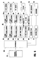
- a principal object of this invention at least in its preferred forms is to provide an apparatus for engraving images which comprises a personal computer, a controller, an X-axis pulse motor driver, a Y-axis pulse motor driver, an X-axis pulse motor, a tilt motor driver, a Z-axis head motor having a minute ⁇ Y-axis driver, a stylus and a vacuum pump whereby photographs of faces, addresses, names, autographs, the images for engraving information identifying one's identity, the images from a digital camera, scanner or other information taken from a computer through a network can be automatically and correctly engraved on identification cards such as passports, drivers' licenses, employee certificates or credit cards.
- identification cards such as passports, drivers' licenses, employee certificates or credit cards.
- Another object of this invention at least in its preferred forms is to provide an apparatus for engraving images whereby a side-by-side comparison of the original image with an engraved image is not required for an operator so that erroneous inputting of information or wrong engraving of another person can be substantially avoided.
- Another object of this invention at least in its preferred forms is to provide an apparatus for engraving images comprising a vibration-preventing unit whereby smooth and correct engraving can be easily carried out without causing vibration.
- Another object of this invention is to provide an apparatus for engraving images, which is simple in construction so as to facilitate easy assembly, operation and maintenance.
- Another object of this invention at least in its preferred forms is to provide an apparatus for engraving images for a passport, identity card and the like whereby various different kinds of adaptors for holding the item to be engraved are prepared in advance in order to exchange the desired adaptors for different types of item without having to use different kinds of engraving apparatus for the different items.
- Another object of this invention at least in its preferred forms is to provide an adaptor for use in an apparatus for engraving images on identification cards, which comprises a rectangular table having a positioning groove and a ridge, which are respectively provided around and near a peripheral edge portion thereof, and a plurality of small air openings provided through the table at the given positions whereby an item to be engraved can be sucked towards and located on the table correctly.
- Still another object of this invention at least in its preferred forms is to provide an adaptor for use in an apparatus for engraving images which comprises a first rectangular table, a second rectangular table which is rigidly secured at a given obtuse angle to the first rectangular table, and a third rectangular table which is pivotally connected to the second rectangular table so that an item to be engraved can be sucked towards and located on the second rectangular table correctly.
- the invention provides an apparatus for engraving images which comprises means for supporting an item to be engraved and engraving means, characterised in that said means for supporting an item to be engraved comprises: a stand comprising a planar surface and a pair of legs rigidly mounted on a base support provided by a base plate having a given thickness and a width, wherein said each leg has an opening provided through a central portion thereof; a spindle penetrated through the openings of said legs supported by and extending between said legs parallel to said planar surface; and a pair of bearings mounted slidably on said spindle to reciprocate, wherein coil springs are provided on the spindle between each said leg and each said bearing to reduce the effect of vibration of the apparatus on a support surface for receiving the item to be engraved, said support surface being provided by a second base plate integrally mounted on the top portion of each bearing; said apparatus further comprising: a controller connected to a personal computer; a pair of driving and driven pulleys provided on a pair of blocks mounted on the second
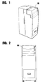
- an apparatus EG for engraving images is connected to a personal computer PC as shown in FIG. 6 .
- the apparatus EG comprises a base plate 10 having a given thickness and a width, on which a ⁇ -shaped driving stand 12 having a pair of legs 12a, 12a and an upper surface extending between the legs is rigidly mounted.
- An opening (not shown) is provided through a central portion of the leg 12a, and a pair of bearings 18, 18, each having an opening (not shown), are made independently.
- Both end portions of a spindle 14 is penetrated through the openings of the bearings 18, 18 and the openings of the legs 12a, 12a with a pair of coil springs 16, 16, each being located between a leg 12a and a bearing 18 respectively.
- the spindle 14 is mounted to extend horizontally and in parallel with the base plate 10 to form a vibration-preventing unit A.
- a second base plate 20a is integrally mounted on the top of each bearings 18, 18, a pair of driving and driven pulleys 36 and 34 are provided on a pair of blocks mounted on the second base plate 20a, a timing belt 38 is engaged on these pulleys 36 and 34, an X-axis feeder 30 is provided on the timing belt 38 and a ⁇ -shaped rail 28 extending parallel to the second base plate 20a and supported above it by legs extending downwardly at either end thereof, and an X-axis pulse motor driver 32 and an X-axis pulse motor 34a are connected to the X-axis feeder 30.
- a Y-axis driver C that is connected to the controller CR of the engraving apparatus EG comprises a Y-axis pulse motor driver 76 and a Y-axis pulse motor 78.
- a Z-axis driver D is provided on a head base, which is a top portion of the Y-axis driver C.
- the Z-axis driver D comprises a Z-axis head driver 54, a Z-axis head 56, a stylus 58 provided at a lower portion of the Z-axis head 56, and a minute ⁇ Y-axis driver E having a ⁇ Y-axis head driver 60 and a ⁇ Y-axis head 62 is connected to the stylus 58.
- a tilt driver F which is connected to the controller CR comprises a tilt pulse motor driver 64 and a tilt pulse motor 66 which is provided at a front portion of the Y-axis driver C so that when an adaptor 80 is tilted rearwards, an item to be engraved such as a passport P or an identification card ID can be easily placed on the adaptor 80.
- a vacuum pump 68 Mounted on the adaptor 80 and near the X-axis pulse motor 34a is a vacuum pump 68, an air hose 68a having a small diameter which is mounted to locate near the X-axis pulse motor 34a to work as a dust absorber 74 of the engraved cut dust or scrap.
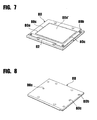
- an adaptor 80 of one embodiment includes a rectangular table having a given thickness and width, and it can be put on the feeder 30.
- FIGS. 7 and 8 another end portion of the air hose 68a is put into the air opening 80c from a backside of the positioning rectangular groove 80a which is provided near an outer periphery of the adaptor 80, a depressed rectangular plane 80a' which is defined by the rectangular groove 80a is lowered slightly by about 0.1mm relative to the outer surface of the adaptor 80, and a pair of small air openings 80c, 80c are provided through the adaptor 80 to locate at the upper and lower grooves 80a, 80a, thus sucking out air from behind the adaptor 80 to hold the media such as an identification card ID on the depressed rectangular portion 80a'.
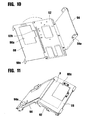
- FIGS. 9-11 An adaptor 90 of an alternative embodiment for engraving images on a passport P is shown in FIGS. 9-11 , in which the adaptor 90 has a holding table 92 and an inclined table 94 which is rigidly secured to one side edge portion of the holding table 92 and a lid plate 98 which is pivotally secured to the other side edge portion of the holding table 92.
- the holding table 92 has a given thickness and width, and a depressed rectangular plane 92a' which is defined by the rectangular groove 92a and is lowered slightly by about 0.1mm relative to the outer surface of the holding table, and a pair of small air openings 92c, 92c which are provided through the adaptor 90 to locate at the upper and lower grooves 92a, 92a, thus sucking air from behind the adaptor to hold the engraved passport P on the depressed rectangular plane 92a'.
- a pair of positioning ridges 96, 96 are provided on a top and a side portion of the holding table 92 respectively, and a rectangular window 98a is provided through the lid plate 98 in order to correspond with the depressed rectangular plane 92a'.
- a pair of clips 94a, 94a are provided at both corner portions of the inclined table 94, and a pair of grips 98c, 98c are mounted at both upper and lower portions of an outer edge portion of the lid plate 98 so that the engraved passport P may be correctly held between the holding table 92 and the lid plate 98 and smooth engraving can be easily carried out without causing vibration.
- the depressed rectangular plane 80a' which is defined by the rectangular groove 80a is lowered slightly by about 0.1 mm, and a pair of small air openings 80c, 80c are provided through the adaptor 80 to locate at the upper and lower grooves 80a, 80a so that media such as an identification card ID can be easily positioned on the depressed rectangular portion 80a' and held on the adaptor 80 by a negative pressure of air (or a vacuum).
- a suction pump, a pressure sensor, an electromagnetic valve and piping are connected to the air hose 68a in order to provide the negative pressure or vacuum required in use.
- the adaptor 90 for engraving images on a passport P comprises a depressed rectangular plane 90a' which is defined by the rectangular groove 90a and is lowered slightly by about 0.1mm, and a pair of small air openings 90c, 90c are provided through the adaptor 90 to locate at the upper and lower grooves 90a, 90a so that the engraved passport P can be disposed on the depressed rectangular portion 90a' to allow a correct and smooth engraving of the engraved passport P.
- the apparatus EG for engraving images on a passport, identification card, or the like is connected to the personal computer PC, an item for engraving such as a magnetic card is manually put onto the adaptor 80 or 90, which is mounted on the X-axis feeder 30, into which one or more images such as a picture of a face, a name, signature, identifying information, etc.
Landscapes
- Engineering & Computer Science (AREA)
- General Engineering & Computer Science (AREA)
- Mechanical Engineering (AREA)
- Credit Cards Or The Like (AREA)
- Manufacture Or Reproduction Of Printing Formes (AREA)
Claims (3)
- Appareil servant à graver des images qui comprend un moyen servant à soutenir un objet destiné à être gravé et un moyen de gravure, caractérisé en ce que ledit moyen servant à soutenir un objet destiné à être gravé comprend : un pied (12) comprenant une surface planaire et une paire de jambes (12A) solidement montée sur un support de base (10) fourni par une plaque de base ayant une épaisseur et une largeur données, dans lequel chaque dite jambe a une ouverture prévue à travers une partie centrale de celle-ci ; une tige (14) entrée à travers les ouvertures desdites jambes supportée par lesdites jambes et s'étendant entre lesdites jambes de façon parallèle à ladite surface planaire ; et une paire de paliers (18, 18) montée de façon coulissante sur ladite tige pour effectuer un mouvement de va-et-vient, dans laquelle des ressorts hélicoïdaux (16) sont fournis sur la tige entre chaque dite jambe et chaque dit palier pour réduire l'effet de vibration de l'appareil sur une surface de soutien (20A) servant à recevoir l'objet destiné à être gravé, ladite surface de soutien étant fournie par une deuxième plaque de base (20a) intégralement montée sur la partie supérieure de chaque palier ; ledit appareil comprenant en outre :un dispositif de commande (CR) relié à un ordinateur personnel (PC) ;➢ une paire de poulies entraînées et d'entraînement (34, 36) fournie sur une paire de blocs montés sur la deuxième plaque de base ;➢ une courroie crantée (38) mise en prise sur lesdites poulies :➢ un rail en forme de Π (28) monté sur la deuxième plaque de base ;➢ un dispositif d'alimentation d'axe X (30) fourni sur ladite courroie crantée et sur ledit rail en forme de Π ;➢ un dispositif d'entraînement de moteur à impulsions d'axe X (32) et un moteur à impulsions d'axe X (34a) relié audit dispositif d'alimentation d'axe X ;➢ un dispositif d'entraînement d'axe Y (C) relié au dispositif de commande ;➢ un dispositif d'entraînement de moteur à impulsions d'axe Y (76) relié à un moteur à impulsions d'axe Y (78) ;➢ un dispositif d'entraînement d'axe Z (D) fourni sur une base de tête, qui est une partie supérieure du dispositif d'entraînement d'axe Y ;➢ un dispositif d'entraînement d'axe Z comportant un dispositif d'entraînement de tête d'axe Z (54) et une tête d'axe Z (56) ;➢ un stylet (58) fourni au niveau d'une partie inférieure de la tête d'axe Z ;➢ un dispositif d'entraînement d'axe ΔY de minute (E) ayant un dispositif d'entraînement de tête d'axe Y et une tête d'axe ΔY reliée audit stylet ; et➢ un dispositif d'entraînement d'inclinaison (F) comprenant un dispositif d'entraînement de moteur à impulsions d'inclinaison (64) et un moteur à impulsions d'inclinaison (66) disposé au niveau d'une partie frontale du dispositif d'entraînement d'axe Y de telle façon que lorsqu'un adaptateur (80, 90) est incliné vers l'arrière, un objet destiné à être gravé tel qu'un passeport P ou une carte d'identité ID peut être facilement placé (e) sur l'adaptateur.
- Appareil selon la revendication 1, comprenant en outre un adaptateur (80 ; 90), qui comprend une table rectangulaire ayant une épaisseur et une largeur données qui est mise sur le dispositif d'alimentation lors de l'utilisation, ladite table rectangulaire ayant une rainure rectangulaire de positionnement (80a ; 92a) fournie près d'une périphérie externe de celle-ci, ladite rainure rectangulaire définissant un plan rectangulaire abaissé (80a' ; 92a') qui est légèrement abaissé d'environ 0,1 mm par rapport à la périphérie externe de la table rectangulaire, une paire de petites ouvertures d'air (80c ; 92c) fournie à travers l'adaptateur pour se situer au niveau des extrémités supérieure et inférieure de la rainure rectangulaire, un tuyau d'air étant disposé derrière ladite table, une partie d'extrémité dudit tuyau d'air étant disposé dans l'ouverture d'air à partir de l'arrière et une autre extrémité étant reliée à une pompe à vide afin de maintenir l'objet destiné à être gravé sur l'adaptateur à travers une pression d'air négative.
- Appareil selon la revendication 2, ledit adaptateur comprenant en outre une table inclinée (94) qui est solidement attachée à une partie de bord latéral de la table rectangulaire (92) et une plaque de couvercle (98) qui est attachée de façon pivotante à l'autre partie de bord latéral de la table rectangulaire, une paire de saillies de positionnement (96) étant fournies respectivement sur une partie supérieure et sur une partie latérale de ladite table rectangulaire, une fenêtre rectangulaire (98a) étant fournie à travers la plaque de couvercle afin de correspondre au plan rectangulaire abaissé (92a'), une paire d'étriers (94a) étant fournie au niveau des deux parties de coin de la table inclinée et une paire d'éléments de serrage (98c) étant montée au niveau des deux parties supérieure et inférieure d'une partie de bord externe de la plaque de couvercle de telle sorte que l'objet destiné à être gravé peut être correctement maintenu entre la table de maintien et la plaque de couvercle et une gravure douce peut être facilement exécutée sans entraîner de vibrations.
Priority Applications (1)
| Application Number | Priority Date | Filing Date | Title |
|---|---|---|---|
| EP05018221A EP1616717B1 (fr) | 2000-09-12 | 2001-09-12 | Adaptateur pour maintenir la pièce à graver pour un dispositif pour graver des images et dispositif correspondant |
Applications Claiming Priority (2)
| Application Number | Priority Date | Filing Date | Title |
|---|---|---|---|
| JP2000318605A JP4498580B2 (ja) | 2000-09-12 | 2000-09-12 | 画像彫刻装置 |
| JP2000318605 | 2000-09-12 |
Related Child Applications (1)
| Application Number | Title | Priority Date | Filing Date |
|---|---|---|---|
| EP05018221A Division EP1616717B1 (fr) | 2000-09-12 | 2001-09-12 | Adaptateur pour maintenir la pièce à graver pour un dispositif pour graver des images et dispositif correspondant |
Publications (4)
| Publication Number | Publication Date |
|---|---|
| EP1195268A2 EP1195268A2 (fr) | 2002-04-10 |
| EP1195268A3 EP1195268A3 (fr) | 2002-07-31 |
| EP1195268B1 true EP1195268B1 (fr) | 2008-07-30 |
| EP1195268B9 EP1195268B9 (fr) | 2009-07-08 |
Family
ID=18797201
Family Applications (2)
| Application Number | Title | Priority Date | Filing Date |
|---|---|---|---|
| EP01307784A Expired - Lifetime EP1195268B9 (fr) | 2000-09-12 | 2001-09-12 | Dispositif pour graver des images et adaptateur correspondant pour maintenir la pièce à graver |
| EP05018221A Expired - Lifetime EP1616717B1 (fr) | 2000-09-12 | 2001-09-12 | Adaptateur pour maintenir la pièce à graver pour un dispositif pour graver des images et dispositif correspondant |
Family Applications After (1)
| Application Number | Title | Priority Date | Filing Date |
|---|---|---|---|
| EP05018221A Expired - Lifetime EP1616717B1 (fr) | 2000-09-12 | 2001-09-12 | Adaptateur pour maintenir la pièce à graver pour un dispositif pour graver des images et dispositif correspondant |
Country Status (8)
| Country | Link |
|---|---|
| US (2) | US20020030318A1 (fr) |
| EP (2) | EP1195268B9 (fr) |
| JP (1) | JP4498580B2 (fr) |
| KR (2) | KR20020021063A (fr) |
| CN (1) | CN100491138C (fr) |
| CA (1) | CA2357228C (fr) |
| DE (2) | DE60138317D1 (fr) |
| TW (1) | TWI276553B (fr) |
Families Citing this family (13)
| Publication number | Priority date | Publication date | Assignee | Title |
|---|---|---|---|---|
| US20080057295A1 (en) * | 2006-09-01 | 2008-03-06 | Fina Technology, Inc. | Engravable board |
| CN102290573B (zh) | 2007-03-30 | 2015-07-08 | 索尼株式会社 | 正极活性物质、正极、非水电解质电池 |
| JP2009096129A (ja) * | 2007-10-18 | 2009-05-07 | Semco Corp | 画像彫刻装置 |
| US8424216B2 (en) * | 2009-11-09 | 2013-04-23 | The Hillman Group, Inc. | Dual-side engraving system |
| CN102431366B (zh) * | 2011-09-15 | 2015-03-11 | 深圳大宇精雕科技有限公司 | 一种自动上下料的精雕机 |
| KR101297899B1 (ko) * | 2013-04-04 | 2013-08-22 | 최신자 | 플라스틱 카드의 스탬핑 위치 자동 조절 방식의 홀로그램 부착장치 |
| JP6582282B2 (ja) * | 2014-10-30 | 2019-10-02 | 株式会社ワールドベンチャー | 画像彫刻装置 |
| WO2017025994A1 (fr) * | 2015-08-11 | 2017-02-16 | セムコ株式会社 | Structure pour support de fixation devant être gravé |
| CN107009794B (zh) * | 2017-05-16 | 2018-09-18 | 安庆市宏大涛业精啄数控科技有限公司 | 一种可转动的雕刻机辅助撑板 |
| CN109955632B (zh) * | 2019-05-06 | 2024-03-08 | 北海绩迅科技股份有限公司 | 一种墨盒的雕刻扩容设备 |
| CN110245612A (zh) | 2019-06-14 | 2019-09-17 | 百度在线网络技术(北京)有限公司 | 人脸图像的检测方法和装置 |
| CN110356156B (zh) * | 2019-07-08 | 2020-11-10 | 浙江易正智能科技有限公司 | 一种平移式车牌打印装置 |
| US11999187B2 (en) * | 2020-08-13 | 2024-06-04 | The Hillman Group, Inc. | Engraving machine for engraving offboard and onboard items |
Family Cites Families (27)
| Publication number | Priority date | Publication date | Assignee | Title |
|---|---|---|---|---|
| US2809005A (en) * | 1954-10-06 | 1957-10-08 | Kenneth E Goode | Shock and vibration mount having non-rotational features |
| US3803979A (en) * | 1972-08-31 | 1974-04-16 | J Young | Engraving apparatus |
| JPS4966223A (fr) * | 1972-10-31 | 1974-06-27 | ||
| US3927599A (en) * | 1972-11-24 | 1975-12-23 | Raymond Jean Louis | Universal engraving machine |
| JPS51138982A (en) * | 1975-05-28 | 1976-11-30 | Tokyo Juki Ind Co Ltd | A device for engraving the image of picture |
| US4385360A (en) * | 1980-08-04 | 1983-05-24 | Micro-Power Computer Systems | Computer-controlled reproduction device |
| JPS5994894U (ja) * | 1982-12-17 | 1984-06-27 | 古河電気工業株式会社 | 画像彫刻用削り滓吸引パイプ |
| FR2596313B1 (fr) * | 1986-03-28 | 1989-06-30 | Gravograph | Systeme de fixation par aspiration d'une plaque a travailler, notamment en gravure |
| IT1201847B (it) * | 1986-09-23 | 1989-02-02 | G L C Di Ceriotti Gino | Procedimento e macchina per incidere le superfici maggiori delle lastre di cristallo con solchi, medioprofondi, anche chiechi, secondo disegni, misitlinei, ripetitivi e loro combinazioni, e lastre di cristallo ottenute con tali procedimento e macchina |
| FR2612329B1 (fr) * | 1987-03-09 | 1989-05-19 | Vibrachoc Sa | Dispositif de suspension autorisant un objet a se deplacer dans un plan |
| FR2633748B1 (fr) * | 1988-06-30 | 1992-03-06 | Schlumberger Ind Sa | Procede et dispositif d'identification d'outil d'ecriture |
| US4989823A (en) * | 1989-04-28 | 1991-02-05 | Leonard Studio Equipment, Inc. | Shock and vibration isolator |
| US5116174A (en) * | 1989-11-13 | 1992-05-26 | Kenneth Fried | Method and apparatus for manufacturing jewelry, and an article of jewelry made thereby |
| FR2664534B1 (fr) * | 1990-07-13 | 1993-09-24 | De Boisgrollier Dominique | Machine de gravure automatique d'objets. |
| JPH04166398A (ja) * | 1990-10-30 | 1992-06-12 | Nec Home Electron Ltd | カード彫刻機のカッター駆動装置 |
| JP2857635B2 (ja) * | 1991-07-24 | 1999-02-17 | 株式会社セブンファースト | 画像彫刻装置 |
| US5512005A (en) * | 1992-08-28 | 1996-04-30 | Michael P. Short | Process and apparatus for automatically engraving stone memorial markers |
| US5504301A (en) * | 1994-03-21 | 1996-04-02 | Laser Cut Images International, Inc. | Apparatus and method for laser engraving thin sheet-like materials |
| US5569003A (en) * | 1994-05-13 | 1996-10-29 | Quick-Tag, Inc. | Automated engraving apparatus and method |
| US5493965A (en) * | 1994-06-16 | 1996-02-27 | Lizarazu; Pio E. | Impact engraving machine |
| JPH0837225A (ja) * | 1994-07-26 | 1996-02-06 | Hitachi Ltd | 半導体製造用治具および前記治具を使用した検査装置 |
| FR2723333B1 (fr) * | 1994-08-08 | 1996-09-20 | Technifor Sa | Dispositif de marquage pour la realisation de signes d'identification a deux dimensions sur la surface d'un objet quelconque |
| FR2729892B1 (fr) * | 1995-01-31 | 1997-07-18 | Nicolas Michel | Dispositif de tables a depression de machines a graver |
| JPH0929923A (ja) * | 1995-07-18 | 1997-02-04 | Dainippon Screen Mfg Co Ltd | グラビア彫刻機の潤滑剤塗布装置 |
| JPH09150599A (ja) * | 1995-11-28 | 1997-06-10 | Roland D G Kk | 材料排出用シューター装置およびそれを備えた彫刻機 |
| US6186711B1 (en) * | 1998-04-03 | 2001-02-13 | Axxess Technologies, Inc. | Engraving system |
| US6046563A (en) * | 1998-08-19 | 2000-04-04 | Moreyra; Manuel R. | Haptic device |
-
2000
- 2000-09-12 JP JP2000318605A patent/JP4498580B2/ja not_active Expired - Lifetime
-
2001
- 2001-09-11 CN CN01138577.4A patent/CN100491138C/zh not_active Expired - Fee Related
- 2001-09-11 TW TW090122470A patent/TWI276553B/zh not_active IP Right Cessation
- 2001-09-12 EP EP01307784A patent/EP1195268B9/fr not_active Expired - Lifetime
- 2001-09-12 DE DE60138317T patent/DE60138317D1/de not_active Expired - Lifetime
- 2001-09-12 CA CA2357228A patent/CA2357228C/fr not_active Expired - Lifetime
- 2001-09-12 DE DE60135075T patent/DE60135075D1/de not_active Expired - Lifetime
- 2001-09-12 KR KR1020010056172A patent/KR20020021063A/ko not_active Ceased
- 2001-09-12 US US09/950,078 patent/US20020030318A1/en not_active Abandoned
- 2001-09-12 EP EP05018221A patent/EP1616717B1/fr not_active Expired - Lifetime
-
2004
- 2004-07-28 US US10/900,330 patent/US6976315B2/en not_active Expired - Lifetime
-
2007
- 2007-08-21 KR KR1020070084097A patent/KR20070088437A/ko not_active Ceased
Also Published As
| Publication number | Publication date |
|---|---|
| KR20020021063A (ko) | 2002-03-18 |
| DE60135075D1 (de) | 2008-09-11 |
| CN1367091A (zh) | 2002-09-04 |
| CA2357228C (fr) | 2010-08-17 |
| EP1195268B9 (fr) | 2009-07-08 |
| TWI276553B (en) | 2007-03-21 |
| EP1195268A2 (fr) | 2002-04-10 |
| KR20070088437A (ko) | 2007-08-29 |
| DE60138317D1 (de) | 2009-05-20 |
| US20050005460A1 (en) | 2005-01-13 |
| EP1616717A3 (fr) | 2007-09-05 |
| US20020030318A1 (en) | 2002-03-14 |
| JP4498580B2 (ja) | 2010-07-07 |
| EP1616717B1 (fr) | 2009-04-08 |
| US6976315B2 (en) | 2005-12-20 |
| CA2357228A1 (fr) | 2002-03-12 |
| EP1195268A3 (fr) | 2002-07-31 |
| EP1616717A2 (fr) | 2006-01-18 |
| CN100491138C (zh) | 2009-05-27 |
| JP2002086993A (ja) | 2002-03-26 |
Similar Documents
| Publication | Publication Date | Title |
|---|---|---|
| EP1195268B1 (fr) | Dispositif pour graver des images et adaptateur correspondant pour maintenir la pièce à graver | |
| US20070056415A1 (en) | Automatic pattern making apparatus | |
| EP1267563A2 (fr) | Produits d'images découpés sur devis | |
| US20070227332A1 (en) | Automatic pattern making apparatus | |
| US20030118689A1 (en) | Embossing system | |
| EP0913738A3 (fr) | Appareil de formation d'images | |
| US20030177682A1 (en) | Document display and retention device | |
| EP1213911A3 (fr) | Procédé et appareil pour la reproduction d'une image avec des instructions de découpage et produit | |
| JP2005027141A (ja) | 原稿読取り装置と原稿載置台の組合せ | |
| JP2005027140A (ja) | ポストカード調製機 | |
| US7568415B2 (en) | Device for cutting mat and liner for double matted framed artwork | |
| JP2596789Y2 (ja) | トリミング用具 | |
| US4975731A (en) | Apparatus for producing a form having driver's license information thereon | |
| US20040221750A1 (en) | Embossing guide | |
| JP3012464U (ja) | 透かし顔写真表示紙葉およびそれを用いた証明書類 | |
| JP2006297874A (ja) | 画像彫刻装置 | |
| WO2007012802A1 (fr) | Scanneur mobile multifonctionnel | |
| JP2007021889A (ja) | Idカード、idカード作成方法、idカード作成プログラム、及びidカード作成用台紙 | |
| JP3077467U (ja) | 各種証明用写真の枠取り用テンプレート | |
| JP2006011615A (ja) | Oa作業台 | |
| Feldmann | Preparation of paleontological plates | |
| JPH01142551A (ja) | 写真類シートおよびその製造装置 | |
| JPH10114184A (ja) | パンチ器にセットする位置を書類上に定める機構を設けたファイル台紙 | |
| JPH1159031A (ja) | 情報入力用抜き型用紙 | |
| JPH05253364A (ja) | ファイル用カッティング定規 |
Legal Events
| Date | Code | Title | Description |
|---|---|---|---|
| PUAI | Public reference made under article 153(3) epc to a published international application that has entered the european phase |
Free format text: ORIGINAL CODE: 0009012 |
|
| AK | Designated contracting states |
Kind code of ref document: A2 Designated state(s): AT BE CH CY DE DK ES FI FR GB GR IE IT LI LU MC NL PT SE TR |
|
| AX | Request for extension of the european patent |
Free format text: AL;LT;LV;MK;RO;SI |
|
| PUAL | Search report despatched |
Free format text: ORIGINAL CODE: 0009013 |
|
| AK | Designated contracting states |
Kind code of ref document: A3 Designated state(s): AT BE CH CY DE DK ES FI FR GB GR IE IT LI LU MC NL PT SE TR |
|
| AX | Request for extension of the european patent |
Free format text: AL;LT;LV;MK;RO;SI |
|
| 17P | Request for examination filed |
Effective date: 20030131 |
|
| AKX | Designation fees paid |
Designated state(s): DE FR GB IT |
|
| 17Q | First examination report despatched |
Effective date: 20050125 |
|
| GRAP | Despatch of communication of intention to grant a patent |
Free format text: ORIGINAL CODE: EPIDOSNIGR1 |
|
| RAP1 | Party data changed (applicant data changed or rights of an application transferred) |
Owner name: SEMCO CORPORATION |
|
| GRAS | Grant fee paid |
Free format text: ORIGINAL CODE: EPIDOSNIGR3 |
|
| GRAA | (expected) grant |
Free format text: ORIGINAL CODE: 0009210 |
|
| AK | Designated contracting states |
Kind code of ref document: B1 Designated state(s): DE FR GB IT |
|
| REG | Reference to a national code |
Ref country code: GB Ref legal event code: FG4D |
|
| REF | Corresponds to: |
Ref document number: 60135075 Country of ref document: DE Date of ref document: 20080911 Kind code of ref document: P |
|
| PLBE | No opposition filed within time limit |
Free format text: ORIGINAL CODE: 0009261 |
|
| STAA | Information on the status of an ep patent application or granted ep patent |
Free format text: STATUS: NO OPPOSITION FILED WITHIN TIME LIMIT |
|
| 26N | No opposition filed |
Effective date: 20090506 |
|
| REG | Reference to a national code |
Ref country code: FR Ref legal event code: PLFP Year of fee payment: 16 |
|
| PGFP | Annual fee paid to national office [announced via postgrant information from national office to epo] |
Ref country code: GB Payment date: 20160919 Year of fee payment: 16 |
|
| PGFP | Annual fee paid to national office [announced via postgrant information from national office to epo] |
Ref country code: FR Payment date: 20160921 Year of fee payment: 16 |
|
| PGFP | Annual fee paid to national office [announced via postgrant information from national office to epo] |
Ref country code: IT Payment date: 20160927 Year of fee payment: 16 |
|
| GBPC | Gb: european patent ceased through non-payment of renewal fee |
Effective date: 20170912 |
|
| REG | Reference to a national code |
Ref country code: FR Ref legal event code: ST Effective date: 20180531 |
|
| PG25 | Lapsed in a contracting state [announced via postgrant information from national office to epo] |
Ref country code: GB Free format text: LAPSE BECAUSE OF NON-PAYMENT OF DUE FEES Effective date: 20170912 |
|
| PG25 | Lapsed in a contracting state [announced via postgrant information from national office to epo] |
Ref country code: IT Free format text: LAPSE BECAUSE OF NON-PAYMENT OF DUE FEES Effective date: 20170912 Ref country code: FR Free format text: LAPSE BECAUSE OF NON-PAYMENT OF DUE FEES Effective date: 20171002 |
|
| PGFP | Annual fee paid to national office [announced via postgrant information from national office to epo] |
Ref country code: DE Payment date: 20190919 Year of fee payment: 19 |
|
| REG | Reference to a national code |
Ref country code: DE Ref legal event code: R082 Ref document number: 60135075 Country of ref document: DE Representative=s name: DEHNS, DE Ref country code: DE Ref legal event code: R081 Ref document number: 60135075 Country of ref document: DE Owner name: SEMCO INTERNATIONAL LIMITED, HK Free format text: FORMER OWNER: SEMCO CORPORATION, TOKYO, JP |
|
| REG | Reference to a national code |
Ref country code: DE Ref legal event code: R119 Ref document number: 60135075 Country of ref document: DE |
|
| PG25 | Lapsed in a contracting state [announced via postgrant information from national office to epo] |
Ref country code: DE Free format text: LAPSE BECAUSE OF NON-PAYMENT OF DUE FEES Effective date: 20210401 |