EP1195561A2 - Kaskade mit Durchlauf-Wärmetauschern zur Brauchwasser- oder Frischwassererwärmung - Google Patents
Kaskade mit Durchlauf-Wärmetauschern zur Brauchwasser- oder Frischwassererwärmung Download PDFInfo
- Publication number
- EP1195561A2 EP1195561A2 EP01123674A EP01123674A EP1195561A2 EP 1195561 A2 EP1195561 A2 EP 1195561A2 EP 01123674 A EP01123674 A EP 01123674A EP 01123674 A EP01123674 A EP 01123674A EP 1195561 A2 EP1195561 A2 EP 1195561A2
- Authority
- EP
- European Patent Office
- Prior art keywords
- heat exchanger
- flow
- heat exchangers
- water
- arrangement according
- Prior art date
- Legal status (The legal status is an assumption and is not a legal conclusion. Google has not performed a legal analysis and makes no representation as to the accuracy of the status listed.)
- Granted
Links
- 238000010438 heat treatment Methods 0.000 title claims description 5
- 239000013505 freshwater Substances 0.000 title 1
- XLYOFNOQVPJJNP-UHFFFAOYSA-N water Substances O XLYOFNOQVPJJNP-UHFFFAOYSA-N 0.000 claims abstract description 92
- 238000000034 method Methods 0.000 claims description 23
- 230000008569 process Effects 0.000 claims description 17
- 230000008859 change Effects 0.000 claims description 10
- 238000010079 rubber tapping Methods 0.000 claims description 8
- 230000002829 reductive effect Effects 0.000 claims description 6
- 239000008399 tap water Substances 0.000 claims description 6
- 235000020679 tap water Nutrition 0.000 claims description 6
- 230000004913 activation Effects 0.000 claims description 2
- 238000010924 continuous production Methods 0.000 claims 1
- 238000005259 measurement Methods 0.000 description 9
- 238000010586 diagram Methods 0.000 description 3
- 230000006870 function Effects 0.000 description 3
- 230000033228 biological regulation Effects 0.000 description 2
- 230000003247 decreasing effect Effects 0.000 description 2
- 238000000605 extraction Methods 0.000 description 2
- 230000009467 reduction Effects 0.000 description 2
- 230000001105 regulatory effect Effects 0.000 description 2
- 230000008901 benefit Effects 0.000 description 1
- 230000015572 biosynthetic process Effects 0.000 description 1
- 238000009529 body temperature measurement Methods 0.000 description 1
- 230000001276 controlling effect Effects 0.000 description 1
- 230000001419 dependent effect Effects 0.000 description 1
- 238000001514 detection method Methods 0.000 description 1
- 230000035622 drinking Effects 0.000 description 1
- 235000020188 drinking water Nutrition 0.000 description 1
- 239000003651 drinking water Substances 0.000 description 1
- 230000005611 electricity Effects 0.000 description 1
- 230000002349 favourable effect Effects 0.000 description 1
- 230000007774 longterm Effects 0.000 description 1
- 230000036961 partial effect Effects 0.000 description 1
- 238000002360 preparation method Methods 0.000 description 1
- 230000000717 retained effect Effects 0.000 description 1
- 230000002441 reversible effect Effects 0.000 description 1
- 238000005070 sampling Methods 0.000 description 1
- 239000004575 stone Substances 0.000 description 1
- 230000002123 temporal effect Effects 0.000 description 1
- 230000007704 transition Effects 0.000 description 1
- 238000011144 upstream manufacturing Methods 0.000 description 1
Images


Classifications
-
- F—MECHANICAL ENGINEERING; LIGHTING; HEATING; WEAPONS; BLASTING
- F24—HEATING; RANGES; VENTILATING
- F24D—DOMESTIC- OR SPACE-HEATING SYSTEMS, e.g. CENTRAL HEATING SYSTEMS; DOMESTIC HOT-WATER SUPPLY SYSTEMS; ELEMENTS OR COMPONENTS THEREFOR
- F24D19/00—Details
- F24D19/10—Arrangement or mounting of control or safety devices
- F24D19/1006—Arrangement or mounting of control or safety devices for water heating systems
- F24D19/1051—Arrangement or mounting of control or safety devices for water heating systems for domestic hot water
-
- F—MECHANICAL ENGINEERING; LIGHTING; HEATING; WEAPONS; BLASTING
- F24—HEATING; RANGES; VENTILATING
- F24D—DOMESTIC- OR SPACE-HEATING SYSTEMS, e.g. CENTRAL HEATING SYSTEMS; DOMESTIC HOT-WATER SUPPLY SYSTEMS; ELEMENTS OR COMPONENTS THEREFOR
- F24D17/00—Domestic hot-water supply systems
Definitions
- the invention is concerned with the preparation of hot water for a central water heating is applicable in large systems.
- Such process water will also for other purposes, e.g. showering or drinking.
- It will be straight out cold service water obtained from a cold water connection, led by a Heat exchanger based on the flow principle, to which hot water is supplied on the primary side becomes.
- This hot water which in the secondary circuit in the flow principle passed cold domestic water heated to it as the hot water Providing hot water users is not in direct contact with the process water.
- the invention is therefore based on the problem of enabling an increased volume throughput of hot water heated in the continuous principle and at the same time maintaining the temperature stability with high accuracy, even with low delivery rates (volume or mass per time).
- Heat exchanger added, its secondary circuit with regard to the cold water supply is then connected in parallel, the secondary circuit with respect to the Hot water output is also connected in parallel, but in Hot water supply path via a separate control of the supplied Hot water volume independently on the temperature of the secondary side (the tap water is regulated.
- the control is carried out by a control unit that both switches on (and "Release") of the cold water connection (claim 5,6), like any other single temperature at the output of the combinatorially interacting sets secondary hot water flow flow (claim 8).
- a measured value is determined, which can be provided for each heat exchanger. If the measured value exceeds - For example, as a tap amount of hot water - the threshold, so given the switching signal for switching on the further heat exchanger (Claim 11, 12, 13).
- the threshold can range between 50% and 100% of the maximum Flow rate of the heat exchanger last switched on, cf. Claim 2 with its alternatives and claim 4. It can also be defined so that one Interconnection of several identical heat exchangers with the same maximum Delivery rate (claim 4) of a respective multiple of a fixed maximum Threshold is assumed when a signal is considered for secondary flow is representatively available as a sum signal.
- each heat exchanger is independent is controllable, both with regard to the measured value recorded for him Flow volume, as well as with regard to the initial temperature and the primary side conveyed volume for the hot water.
- the basically operated heat exchanger which is regularly switched on first, can also be implemented without an additional control valve that connects to the cold water opens when the threshold is exceeded.
- it can but be of advantage to provide all heat exchangers with such a valve and to leave one of the heat exchangers switched on regularly via the on-off valve and the other heat exchangers when the respective limit of the previous heat exchanger via the respective on-off valve.
- a variation of the initial load can also be available heat exchanger, so that a uniform use of all in time cascade switched heat exchanger is achieved in the long term.
- the threshold value can be specified over a wide range, depending on the application and depending on the size of the heat exchanger. Will the Threshold in a range below 20% of the nominal power of each Heat exchanger, so a relatively early connection of the next one takes place Heat exchanger instead. Such early engagement of the next one Heat exchanger lowers the pressure fluctuations at the time of switching on then two or more parallel flow paths actually have equal rights stand next to each other. The pressure loss of several early connected in parallel Heat exchangers are lowered and in terms of the pumped domestic water Equalizing vibrations at the output with regard to temperature can also be found in only to a lesser extent.
- This position is suitable if there is already a switchover above 5% of the nominal output the threshold for small exchangers with a volume promotion of less than 30 liters / min.
- the threshold value changes, to switch the next heat exchanger that was just switched on avoid.
- the reduction is such that a distribution of the previously in the active heat exchanger or on the number of after Switching on heat exchangers connected in parallel does not result in switching off of the newly added heat exchanger in its secondary circuit takes place. There is for the lowering of the threshold at the triggering Heat exchangers are therefore dependent on the number of parallel connections Heat exchanger.
- the threshold of the newly added exchanger remains equal.
- the flow is ideally distributed evenly over the parallel ones Heat exchangers, each related to the secondary side. With two connected in parallel Exchangers are then reduced the threshold to a value below half of the maximum delivery volume is provided while reducing the Threshold to two thirds occurs when a third heat exchanger is added. If a fourth heat exchanger is added, one results Threshold reduction to a value below Wert. As a comparison value the same threshold value that was previously used based on the Claims 2 was described.
- each heat exchanger has its own control of the Dispensing temperature by setting the primary hot water supply and its volume flow.
- the control signals for switching on the secondary Circuits that are already designed to be connected in parallel only through a valve only one after the other, depending on the volume output to be delivered can be added, can be executed with a control logic that is not in the actual control of the individual heat exchangers intervenes. Rather, they remain themselves left alone.
- a signal (measured value or setpoint) can also be used this is at least approximately representative, based on the time range at which the threshold is reached. This does not have to be proportionality.
- the tapped flow rate drops at several heat exchangers connected in parallel according to a lower requirement, the heat exchangers switch slowly back, i.e. one after the other, according to the sinking and the selected threshold values are removed from the active parallel connection.
- the threshold values are changed accordingly in reverse, that is to say with one Locking a heat exchanger increases the threshold because, as a result of the switched-off heat exchanger, the still flowing flow on a smaller number of heat exchangers distributed and therefore an increase in Flow in each heat exchanger is the result.
- the dimensioning is too take place that a renewed release of the heat exchanger just switched off is avoided.
- the practical threshold values are usually 10% to 20% below the theoretical Thresholds.
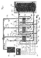
- FIG. 1 illustrates an overall circuit diagram of three heat exchangers 1,2,3, which are interconnected in a network. They are fed together by a memory K on the primary side. The interconnected heat exchangers 1, 2, 3 feed together on the secondary side a collecting line WW which leads to at least one consumer 50 in the house.
- a return circulation line 51 can be returned from the collecting line to one of the fresh or cold water inlets 10 of the three heat exchangers in order to achieve a substantially uniform temperature of the service water at the tap 50 in the entire line WW even when there is little used water removed.
- a control unit 60 is provided with a plurality of input signals 61, 62, 63 and output manipulated variables 64, 65 and 67 and controls the interconnected arrangement of the three heat exchangers shown on the basis of a predetermined control program.
- a heat exchanger is to be explained in the following, the reference symbols increased by ten each for the second heat exchanger 2 and increased by a further ten for the third heat exchanger 3 and denote the same elements.
- the system with the three heat exchangers 1 to 3 shown can be expanded as desired, but at least two individual heat exchangers are required for an interconnection, as can be seen from FIG. 2 , which will be explained later.
- the hot water HW gives that - mostly not reached - maximum temperature again, the hot water on the Secondary side of the heat exchanger should receive.
- the primary page is about the Feed pump 13a with the hot water, while that from the Heat exchanger returning hot water in the return RL the storage again is fed.
- a control valve 16 is provided in the return so that at System shutdown a blind circulation is blocked and the risk of stone formation is reduced on the drinking water side. Only when there is a flow on the Secondary side of the heat exchanger is detected, the control unit 60 switches the Valve 16 on to start the primary circulation and controls the delivery rate the feed pump 13a.
- a temperature at the temperature sensor 14 at the inlet of the heat exchanger 1 is measured and fed to the control unit 60 via one of the lines 62.
- One of the Lines 65 controls the valve 16 in the primary circuit and one of the lines 62 gives the Input temperature value of the first heat exchanger on the primary side, measured from the sensor 14 to the control device 60.
- One of the lines 64 controls the Feed pump 13a in the hot water inlet 13.
- a measuring element 11 On the secondary side, a measuring element 11 is provided, which a flow in Secondary circuit detected and the control unit 60 as a measured value via one of the lines 61 supplies.
- a temperature sensor 15 on the secondary side detects the temperature on Output or in the output area of the heat exchanger 1 and performs this measurement to the control unit 60 via one of the lines 63.
- the outlet pipe for the warm DHW is 12.
- the heat exchanger works in the counterflow principle, so that it is already strong heated secondary water at the high temperature primary hot water flows past and the flows in the heat exchanger on the The primary side and secondary side are directed in opposite directions.
- this one heat exchanger system also applies to the two other heat exchanger systems 2 and 3.
- system 2 whose output line 22 is also on the secondary side Valve 20a provided on the secondary side in the cold water inflow 20. This valve is controlled by the control unit 60.
- a similar valve 30a is in the Cold water inflow 30 of the third heat exchanger 3 is provided, which also has a of control lines 67 is controlled by control unit 60.
- control unit 60 In the first Heat exchanger 1, such a valve is not provided in the cold water inflow 10, it can also be added there, which is a further embodiment variant, the to be described later.
- the function of the three connected in parallel at the output (downstream) Heat exchanger 1,2,3 is accessible through the interconnection of the three Output lines 12, 22 and 32 and via the interconnection of the three Cold water inlet pipes 10, 20 and 30, all upstream (inlet) are connected together to a fresh or cold water supply KW.
- the control works with a regulation on the temperature detected on the secondary side Sensor 15 and the tapping quantity determined by measured value on sensor 11.
- the flow pump 13a as the feed pump is proportional to the heat requirement controlled, with open valve 16.
- the valve 16 opens after the sensor 11 in the Secondary circuit the start of a tap of service water at the tap 50 signaled.
- the control unit 60 switches the second Heat exchanger 2 by switching on (opening) the local control valve 20a.
- the Temperature values of sensors 15 and 25 should be the same and work accordingly the controller 60 by adjusting individual speeds of the feed pumps 13a and 23a.
- the valve 20a (also 30a) is not a proportional valve, but an on / off valve designed so that only the cold water inflow is generally opened when the first heat exchanger 1 does not provide the required tapping capacity while maintaining the same Temperature can provide, or remains closed when the first heat exchanger is sufficient for the required and used tap quantity of the consumer 50.
- the first threshold can be set to range between 90% and 100% of the nominal delivery rate of the first heat exchanger 1 is.
- the second Threshold value of the second heat exchanger 2 is in terms of the delivery rate of the second exchanger 2 dimensioned accordingly.
- the threshold can be adjusted accordingly However, the circumstances can also be changed in such a way that the value of a maximum conveying capacity is set or to the limit of the nominal capacity, so that a abrupt transition between the two heat exchangers 1, 2 is achieved.
- the parallel connection by specifying threshold values can also be done here summarized discussed implementation variants are modified. So is one Parallel connection does not necessarily make sense only if a performance limit of previous heat exchanger or the one already connected in parallel previous multiple heat exchangers is reached.
- active parallel connection are characterized, compared to that of a passive Parallel. All permanently installed heat exchangers 1,2,3 are passive on the Secondary side connected in parallel, so have the ability to connect in parallel and are through pipelines 10, 20, 30 and 12, 22, 32 and secondary flow path in the respective heat exchanger already connected in parallel. It there is only one valve that was previously described with 20a, 30a and that as Valve 10a can also be inserted into line 10 to the first primary exchanger. This valve separates the active from the passive parallel connection. If it is on, this flow path is active, if it is switched off, there is only the possibility a parallel connection, and a passive parallel connection is provided.
- the state is achieved by adding one Threshold.
- Threshold This can depend on the area of application, on the number of Heat exchanger and varies widely depending on the size of the heat exchanger actually, it can cover the entire range of funding volume per Take heat exchangers, i.e. between 5% and practically 100%, that switching on the next heat exchanger, thus transferring it Heat exchanger in the active parallel state, sooner or later reached becomes.
- a hysteresis is also advantageously provided during the switching process, which ensures that that a shutdown of a heat exchanger with decreasing removal of the Consumer 50 takes place only at a significantly lower volume value than that Value at which the connection was made.
- a range from 5% to 10% of the Nominal funding margin has proven to be favorable.
- a tap quantity of, for example up to 320 l / min would lead to such a single device being tapped Flow rates of 5 l / min no longer maintain the temperature with sufficient accuracy could.
- the heat exchangers 1, 2 and 3 described which are in the nominal range of 20 l / min, 30 l / min or 40 l / min are, i.e. with outputs significantly below 100 l / min Nominal flow rate work, provide a precisely controllable temperature control ready, with any expandable dispensing volume, by adding one another heat exchanger, which is connected in parallel on the secondary side and via on the primary side another valve corresponding to the valves 20a, 30a is initially blocked.
- the device 60 can also work so that one at a time changing heat exchanger meets the initial load while switching on the another and the next heat exchanger is changed accordingly. So everyone can Heat exchanger in the course of an overall system and in a given one Time schedule once meet the base load for a certain first period of time a different heat exchanger for the maximum amount of tap water is available and in this respect mostly remains in the waiting state, in which the inlet valve 20a, 30a is not switched on.
- the described control signals of the line groups 64, 65 each have so many Control lines, such as feed pumps 13a, 23a, 33a or check valves 16, 26, 36 must be operated.
- the control lines 67 control those described Inlet valves 20a, 30a, which are switched on in succession depending on the flow rate become.
- the measurement signals of line groups 61, 62 and 63 correspond to the number the heat exchanger used.
- a measurement signal in group 63 be provided, which measures the primary temperature of the memory K and the Control unit 60 also feeds.
- FIG. 2 A minimal circuit arrangement is shown in FIG. 2 , in which two heat exchangers 1, 2 are used.
- the primary circuit I is shown inside, the secondary circuit II is shown outside.
- the cold water inflow of the first heat exchanger 1 leads into the heat exchanger and an outlet 12 at the first heat exchanger leads to the extraction point 50.
- the second heat exchanger 2 is provided, only connected in parallel on the secondary side at 22, with an inlet of the cold water via a switching Valve 20a, which is controlled via a control line 67.
- the secondary side of the second heat exchanger 2 is 22 and also leads to the tap 50.
- the sum of the flow rates of the two heat exchangers is available for the removal of hot water from hot water WW.
- a parallel connection is also provided on the primary side, each Heat exchanger, however, independently and individually via a feed pump P, which the Feed pump 13a, 23a of Figure 1 corresponds to be controlled in its heat supply can.
- a feed pump P which the Feed pump 13a, 23a of Figure 1 corresponds to be controlled in its heat supply can.
- the valve 20a switches - for example as Motor valve - via the manipulated variable 67 and allows the inflow of cold water into the second heat exchanger 2 to get there from the hot water and the primary pump P to be warmed up. Its volume flow in the outlet line 22 adds up to Volume flow of the output line 12 of the first heat exchanger, so that seamless and an additional delivery rate without significant temperature fluctuation is provided, which allows a higher delivery rate at the tap 50.
- the recording of the delivery rate (per time) can be at any point of the Flow paths take place on the secondary side.
- Such a flow measurement can also take place indirectly by means of a temperature measurement or a difference measurement, as well as other sensors that need not be vane wheels can find.
- Setpoints can also be used, provided that they are sufficient Representation of the secondary flow flow is provided, at least for the area in which the threshold is reached.
- One is particularly cheap Proportionality and a direct measurement of the secondary amount of hot water.
- the use of others representing these is also sufficient System sizes, such as the delivery rate of the primary pump on the Primary side, which the control technology also provides as a setpoint becomes.
- This "measured variable" can therefore be a target value, a real measured value or a synthetic one generated value so that it should be referred to as a signal that is representative for the secondary flow.
- FIG. 3 explains how the threshold value influences the switching state of the system according to FIG. 1 or for two heat exchangers according to FIG. 2.
- the mass flow is shown as a continuous quantity m (t), once for the first heat exchanger m 1 (t), once for the second heat exchanger m 2 (t) and for FIG. 1 also as a third mass flow m 3 (t) .
- the first threshold value g 1 which corresponds to the maximum delivery rate in the example, is reached, the valve 20a is switched on, which leads to Time t 1 happens.
- the threshold value g 1 has been reduced at the time t 1 . He has been reduced here to a level below 2 g, which is less than g1 / 2 to avoid switching back. This can be seen clearly in FIG. 3.
- the consumption at the tapping point WW increases again. It rises evenly in both heat exchangers 1, 2, whereby reference is not made here to the other control processes of the primary pumps 13 a, 23 a, which require correspondingly higher delivery volumes to take account of the increased demand and the temperature at the measuring point 15, 25 in each case individually to keep constant for each heat exchanger.
- the increase up to time t 4 is clearly shown.
- the second heat exchanger 2 reaches the maximum flow value g 1 as an unchanged threshold value on the basis of the signal which is taken from the flow measurement 21 there. Another valve switches again, this time valve 30a in FIG. 1.
- each heat exchanger takes on 2/3 of the total load, which leads to a sharp increase in the third heat exchanger, which can be seen in the third partial image of FIG. 3.
- the threshold value is lowered as a step function at the time t 4 , to a value below g 3 , that is to say below a value of 2/3, in order to avoid a switching back of the valve 30a.
- the change in the threshold values is carried out by the control device 60, to which the measured variables 11, 21, 31 are supplied according to FIG. 1 or 2. Instead of these three The only measurand 11 or 21 or 31 can also be used if this comparison takes into account how many heat exchangers in parallel are switched on.
- the other signals described above, for example Setpoints of the primary pumps 13a, 23a, 33a or only one of these pumps can Used to compare against the thresholds.
- this threshold value can also be used be adapted to achieve an optimized operating state.
- a threshold value can be determined so that it is at a point in the course between the minimum and maximum output of the respective heat exchanger placed, which is determined by a decrease in its initial temperature is detected by sensor 15. But these are more accurate and more responsive Threshold recognition based on the output because it is the actual disturbance of the system is. It is activated by the user on the sampling valve adjusted and only affects the control process on the heat exchanger 1. On The immediate detection of the change in this flow value is therefore the most immediate and fastest measured variable for determining a system state, of based on which comparisons take place, which and how many other heat exchangers must be switched on one after the other.
- FIG. 4 The example mentioned above is shown schematically in FIG. 4 , in which all heat exchangers 1, 2 and 3 each have a switching valve, for example an engine valve 10a, 20a, 30a, which are controlled by a control line assembly 67 from individual control lines 67a, 67b, 67c. All other states and devices are as in FIG. 1, and the individual mass flows m 1 (t) and m 2 (t) and m 3 (t) are shown, as can be seen in FIG. 3, in order to collectively at the outlet as M (t ) to be delivered.
- a switching valve for example an engine valve 10a, 20a, 30a
- a control line assembly 67 from individual control lines 67a, 67b, 67c.
- All other states and devices are as in FIG. 1, and the individual mass flows m 1 (t) and m 2 (t) and m 3 (t) are shown, as can be seen in FIG. 3, in order to collectively at the outlet as M (t ) to be delivered.
- valve 20a from FIG. 2 or all of them Valves 10a, 20a and 30a also disappear from FIG. 4, that is to say only one parallel connection in FIG Provided a permanent active parallel connection of all heat exchangers his.
- the threshold values of FIG. 3 are then not required Compensation processes do not take place. But every heat exchanger itself independently controlled with regard to the output temperature at sensor 15, 25, 35.
- the pumps P according to FIG. 2 can also be controlled in a temperature-controlled manner in such a way that that a sensor detects the return temperature of the water from the particular Heat exchanger determined and the pump P switches off when this return temperature exceeds a limit, e.g. the temperature of the hot water HW at the inlet, measured via either sensor 63a or sensor 14 (or 24.34) on Heat exchanger, minus 5 ° C.
- the pump P is then no longer proportional operated, but completely switched off.
- the activation and release of the further Regular operation of the circulation pump only takes place again when the measured Return temperature around an additional threshold, e.g. 2 ° C has decreased, which is due to the further removal of the process water from the Secondary circuit is initiated. This guarantees warm water at the tap present, but the circulation pump P has to run less often and electricity can be used for this pump can be saved.
Landscapes
- Engineering & Computer Science (AREA)
- Physics & Mathematics (AREA)
- Thermal Sciences (AREA)
- Chemical & Material Sciences (AREA)
- Combustion & Propulsion (AREA)
- Mechanical Engineering (AREA)
- General Engineering & Computer Science (AREA)
- Heat-Pump Type And Storage Water Heaters (AREA)
- Steam Or Hot-Water Central Heating Systems (AREA)
- Instantaneous Water Boilers, Portable Hot-Water Supply Apparatuses, And Control Of Portable Hot-Water Supply Apparatuses (AREA)
- Separation Using Semi-Permeable Membranes (AREA)
- Heat Treatment Of Water, Waste Water Or Sewage (AREA)
Abstract
Description
- Figur 1
- ist ein Hydraulikschaltplan einer Kaskadensteuerung mit drei Wärmetauschern 1, 2, 3, einem Speicher K und einem Brauchwasserverbraucher 50.
- Figur 2
- ist ein schematisches Schaltbild von zwei Wärmetauschern 1,2, die in Kaskade geschaltet sind und einen Verbraucher 50 versorgen.
- Figur 3
- ist ein Verlauf der geförderten Volumenströme mi(t) bei i=1,2,3,...n von drei sekundärseitig nacheinander parallel geschalteten Wärmetauschern, wie in Figur 1 dargestellt, wobei Schwellenwerte g1,g2 und g3 eingezeichnet sind.
- Figur 4
- ist eine schematische Skizze einer Anordnung ähnlich der von Figur 1, nur mit zusätzlichem Schaltventil 10a am ersten Wärmetauscher, wobei die relevanten Steuerungsleitungen beibehalten wurden und die übrigen Steuerleitungen zur Schaffung von Übersichtlichkeit fortgelassen wurden.
Claims (26)
- Anordnung zum Bereitstellen von warmem Frisch- oder Brauchwasser (WW), bei welcher Anordnungvon einem Kaltwasseranschluß (KW) kaltes, unter Druck stehendes Brauchwasser zumindest zwei sekundärseitig an einem Ausgang parallel geschalteten (12,22,32) Wärmetauschern (1,2,3) zuführbar ist;jedem der Wärmetauscher (1,2,3) über einen im Durchfluß veränderbaren primären Strömungspfad (13,13a;23,23a) heißes Wasser (HW) aus einer Heißwasserquelle (K) zuführbar ist;die Wärmetauscher (1,2,3) im Durchlaufbetrieb arbeitsfähig sind und zumindest ein Signal (11,21,31) erzeugt wird, das für einen aktuellen Durchfluß (Volumenstrom, Massestrom) des ersten Wärmetauschers (1) zumindest im wesentlichen repräsentativ ist;zumindest ein Schwellenwert vorgegeben ist (60,g1), wobei ein Erreichen dieses Schwellenwertes durch das Signal ein Zuschalten (20a) des zweiten Wärmetauschers (2) veranlaßt, um am sekundärseitigen Warmwasser-Ausgang (WW) die Summe von mehreren Volumenströmen, zumindest aber der beiden Wärmetauscher abzugeben.
- Anordnung nach Anspruch 1, wobei der Schwellenwert im Bereich zwischen 20% und 80% der maximalen Förderleistung oder der Nenn-Förderleistung des zuerst aktiven Wärmetauschers (1) oder desjenigen Wärmetauschers (2,3) liegt, der zuletzt zugeschaltet worden ist; oderdas Zuschalten erfolgt, wenn der zuletzt eingeschaltete Wärmetauscher seine Leistungsgrenze zu überschreiten droht.der Schwellenwert im Bereich zwischen 50% und 60% der maximalen Förderleistung oder der Nenn-Förderleistung des zuerst aktiven Wärmetauschers (1) oder desjenigen Wärmetauschers (2,3) liegt, der zuletzt zugeschaltet worden ist; oderder Schwellenwert im Bereich zwischen 50% und 100% der maximalen Förderleistung oder der Nenn-Förderleistung des zuerst aktiven Wärmetauschers (1) oder desjenigen Wärmetauschers (2,3) liegt, der zuletzt zugeschaltet worden ist; oderder Schwellenwert im Bereich zwischen 5% und 20% der maximalen Förderleistung oder der Nenn-Förderleistung des zuerst aktiven Wärmetauschers (1) oder desjenigen Wärmetauschers (2,3) liegt, der zuletzt zugeschaltet worden ist; oder
- Anordnung nach Anspruch 1, wobei ein dritter Wärmetauscher (3) vorgesehen ist und ein weiterer Schwellenwert vorgegeben ist (60,g1), wobei ein Überschreiten dieses Schwellenwertes ein Zuschalten (30a) des dritten Wärmetauschers (3) veranlaßt, um am sekundärseitigen Ausgang (WW) der drei Wärmetauscher (1,2,3) die Summe von drei Volumenströmen abzugeben.
- Anordnung nach Anspruch 3, wobei der weitere Schwellenwert im Bereich zwischen 100% und 50% der maximalen oder Nenn-Förderleistung des zweiten Wärmetauschers (2) liegt oder in einem Bereich nach einem der Ansprüche 2 bis 2d.
- Anordnung nach Anspruch 1 oder 3, wobei das Zuschalten des zweiten, dritten oder eines weiteren Wärmetauschers (2,3) durch Öffnen eines Ventils (20a,30a), insbesondere in der Zufuhr des Kaltwassers (KW) zum zweiten, dritten oder weiteren Wärmetauscher (2,3), erfolgt.
- Anordnung nach Anspruch 5, wobei das jeweilige Ventil (20a,30a) jeweils ein eigenständig ansteuerbares, insbesondere motorisch betriebenes Ventil zur Veränderung des Strömungsquerschnitts an einer Stelle des Sekundärpfades (II) ist.
- Anordnung nach Anspruch 1, wobei die Wärmetauscher eine solche Nenn-Förderleistung haben, die unterhalb von 100 l/min, insbesondere unterhalb von 50 liter/min liegt, wobei insbesondere die mehreren Wärmetauscher eine im wesentlichen gleiche Nenn-Abgabemenge pro Zeit oder Förderleistung (liter/min) besitzen.
- Anordnung nach Anspruch 1 oder 3, wobei eine Abgabetemperatur des erwärmten Brauchwassers nahe eines sekundären Ausgangs jedes Wärmetauschers gemessen wird (15,25) und einem Steuergerät (60) zugeführt wird.
- Anordnung nach Anspruch 1, wobei die Eingangstemperatur des Heißwassers (HW) zu jedem der mehreren Wärmetauscher (1,2,3) erfaßt (34,24,14) und dem Steuergerät (60) zugeführt wird.
- Anordnung nach Anspruch 1, wobei ein Steuergerät (60) vorgesehen ist, das den sekundärseitigen Durchfluß-Strömungspfad (II) zumindest eines der Wärmetauscher, insbesondere des zweiten Wärmetauschers, für eine Strömung öffnet (67,20a), wobei der Strömungspfad vom Kaltwasser-Anschluß (KW) zum Warmwasser-Ausgang (12,22) des warmen Brauchwassers des jeweiligen Wärmetauschers reicht, und wobei die Öffnung des sekundären Strömungspfades dann erfolgt, wenn der Schwellenwert überschritten wird oder die Förderleistung des zuletzt eingeschalteten Wärmetauschers (2) oder der insgesamt zugeschalteten Wärmetauscher (1,2) der gezapften Brauchwassermenge nicht mehr nachfolgen kann.
- Anordnung nach Anspruch 1, wobei das Signal als ein Meßwert (11,21,31) im wesentlichen proportional zum Durchfluß oder zum Volumen bzw. zur Masse pro Zeitintervall (Δm/Δt) ist.
- Anordnung nach Anspruch 1 oder 11, wobei das Signal bzw. der Meßwert repräsentativ für den sekundären Durchfluß durch den einen Wärmetauscher (1) ist.
- Anordnung nach Anspruch 12, wobei an mehreren Wärmetauschern (1,2) jeweils ein Meßwert erfaßt wird, der jeweils repräsentativ für den jeweiligen sekundären Durchfluß des jeweiligen Wärmetauschers (1,2) ist und jeder Meßwert mit einem eigenen Schwellenwert verglichen wird.
- Anordnung nach Anspruch 13, wobei der erste Wärmetauscher (1) der sekundärseitig (12,22,32) parallel geschalteten mehreren Wärmetauschern (1,2,3) kein schaltbares Ventil (10a) im Verlauf der sekundären Strömungsseite besitzt.
- Anordnung nach Anspruch 1, wobei das zumindest eine Signal (11,21,31) ein Sollwert oder ein Istwert einer Förderpumpe (13a) in dem im Durchfluß veränderbaren Strömungspfad (13a,13) einer der Primärseiten der zumindest zwei Wärmetauscher (1,2) ist.
- Anordnung nach Anspruch 1 oder 3, wobei der Schwellenwert (g1,g2,g3) unterhalb des maximalen Förderstroms (Volumen oder Masse pro Zeit) des jeweiligen Wärmetauschers liegt, der über eine Steuereinrichtung (60) das Zuschalten (20a,30a) des nächsten Wärmetauschers (2,3) veranlaßt, der vor Überschreitung des Schwellenwertes noch nicht zugeschaltet war.
- Anordnung nach Anspruch 1 oder 16, wobei der Schwellenwert (g1) herabgesetzt wird (g2,g3), nachdem das fluß-repräsentative Signal den unveränderten Schwellenwert überschritten hat.
- Anordnung nach Anspruch 17, wobei das Herabsetzen des gerade überschrittenen Schwellenwertes dazu führt und ein solches Ausmaß besitzt, daß die veranlaßte Zuschaltung (20a) des nächsten Wärmetauschers (2) und die Aufteilung der Strömungen in den dann mehreren parallel geschalteten Wärmetauschern (1,2) nicht mehr zu einem Zurückschalten des gerade eingeschalteten sekundären Strömungspfades des nächsten Wärmetauschers führt.
- Anordnung nach Anspruch 18, wobei(i) die Herabsetzung des Schwellenwertes beim ersten Wärmetauscher und nach dem Zuschalten des zweiten Wärmetauschers (2) auf im wesentlichen die Hälfte oder weniger bewirkt wird (g2); und/oder(ii) wobei das Herabsetzen des dem zweiten Wärmetauscher (2) zugeordneten Schwellenwerts (g2) auf ein Drittel oder weniger erfolgt (g3), nachdem der dritte Wärmetauscher (3) über ein diesem zugeordnetes Ventil (30a) im sekundären Strömungspfad zugeschaltet worden ist.
- Verfahren zum Betreiben einer Anordnung von zumindest zwei Brauchwassererwärmern (1,2,3), die sekundärseitig parallel geschaltet sind (12,22), zur Abgabe eines Summen-Volumenstroms von erwärmtem Brauchwasser (WW) und wobeium eine große Zapfmenge (Brauchwassermenge pro Zeit) bei hoher Genauigkeit der Temperatur des sekundären erwärmten Wassers (WW) zu erreichen.(a) bei einer ersten Zapfmenge (Brauchwassermenge pro Zeit), die größer ist, als eine maximal mögliche Zapfmenge (in liter/min) durch den einen Wärmetauscher, der andere oder zweite Wärmetauscher (2) parallel zugeschaltet ist und auch ihm Brauchwasser zum Erwärmen im Durchlaufverfahren zugeführt wird (20a);(b) bei einer zweiten gezapften Brauchwassermenge (Zapfmenge), die wesentlich unterhalb des maximalen Volumenstroms des einen oder ersten Wärmetauschers (1) liegt, nur dieser Wärmetauscher (1) im Durchflußprinzip zugeschaltet ist, ohne den zweiten Wärmetauscher am sekundären Strom des Warmwassers zu beteiligen;
- Verfahren nach Anspruch 20, wobei die wesentlich unterhalb des maximalen Volumenstroms liegende zweite Zapfmenge gemäß Merkmal (b) zwischen 50% und 80% der normalen Zapfmenge (Nenn-Zapfleistung) des ersten Wärmetauschers (1) ist.
- Verfahren nach Anspruch 20, wobei ein Überschreiten eines vorgegebenen Schwellenwerts (g1) in einem Steuergerät (60) eine Ansteuerung eines Ventils (20a) bewirkt, die einen weiteren sekundären Strömungspfad (22) für das gezapfte Brauchwasser öffnet, um mehr als ein, insbesondere mehr als zwei Wärmetauscher sekundär parallel zu betreiben.
- Verfahren nach Anspruch 22 oder 20, wobei der Schwellenwert nach Auslösen eines Zuschaltens des nächsten Wärmetauschers herabgesetzt wird (g2).
- Verfahren nach Anspruch 1, 20 oder 23, wobei die praktischen Schwellenwerte zwischen 10% bis 20% unter den theoretischen Schwellenwerten (g1,g2,g3) liegen.
- Verfahren nach Anspruch 20 oder Anordnung nach Anspruch 16, wobei das Herabsetzen des Schwellenwertes nach Zuschalten des nächsten Wärmetauschers, insbesondere der Freigabe des sekundären Strömungspfades des nächsten Wärmetauschers, abhängig von der Anzahl der zugeschalteten und sekundärseitig in freier Strömungsverbindung parallel geschalteten Wärmetauschern ist.
- Anordnung zum Bereitstellen von warmem Brauchwasser (WW), bei welcher Anordnungvon einem Kaltwasseranschluß (KW) kaltes, unter Druck stehendes Nutz- oder Brauchwasser zumindest zwei sekundärseitig an einem Ausgang parallel geschalteten (12,22,32) Wärmetauschern (1,2,3) zuführbar ist;jedem der Wärmetauscher (1,2,3) über einen im Durchfluß veränderbaren primären Strömungspfad (13,13a;23,23a) stark erwärmtes Wasser (HW) zuführbar ist, wobei die Wärmetauscher (1,2,3) im Durchlaufbetrieb arbeitsfähig sind,um an einem sekundärseitigen Warmwasser-Ausgang (WW) die Summe von mehreren getrennt erwärmten einzelnen Volumenströmen als Summen-Volumenstrom abzugeben.
Applications Claiming Priority (2)
| Application Number | Priority Date | Filing Date | Title |
|---|---|---|---|
| DE10048912 | 2000-10-03 | ||
| DE10048912.5A DE10048912B4 (de) | 2000-10-03 | 2000-10-03 | Frischwasserkaskade mit Wärmetauschern |
Publications (3)
| Publication Number | Publication Date |
|---|---|
| EP1195561A2 true EP1195561A2 (de) | 2002-04-10 |
| EP1195561A3 EP1195561A3 (de) | 2003-07-02 |
| EP1195561B1 EP1195561B1 (de) | 2007-05-30 |
Family
ID=7658518
Family Applications (1)
| Application Number | Title | Priority Date | Filing Date |
|---|---|---|---|
| EP01123674A Expired - Lifetime EP1195561B1 (de) | 2000-10-03 | 2001-10-02 | Kaskade mit Durchlauf-Wärmetauschern zur Brauchwasser- oder Frischwassererwärmung |
Country Status (3)
| Country | Link |
|---|---|
| EP (1) | EP1195561B1 (de) |
| AT (1) | ATE363633T1 (de) |
| DE (2) | DE10048912B4 (de) |
Families Citing this family (4)
| Publication number | Priority date | Publication date | Assignee | Title |
|---|---|---|---|---|
| DE10348536B4 (de) * | 2003-10-18 | 2023-02-02 | Roland Sailer | Anordnung zur Erwärmung von Brauchwasser |
| US7962208B2 (en) | 2005-04-25 | 2011-06-14 | Cardiac Pacemakers, Inc. | Method and apparatus for pacing during revascularization |
| EP2413047B2 (de) † | 2010-07-30 | 2021-11-17 | Grundfos Management A/S | Brauchwassererwärmungseinheit |
| AT13435U3 (de) * | 2013-08-22 | 2015-02-15 | Ms Schwarz Gmbh | Anlage zur Erzeugung von erwärmtem bzw. erhitztem Wasser für sanitäre Zwecke sowie Verfahren zum Betrieb dieser Anlage |
Citations (1)
| Publication number | Priority date | Publication date | Assignee | Title |
|---|---|---|---|---|
| DE4035115C2 (de) | 1990-03-12 | 1993-11-04 | Sandler Energietechnik | Anordnung zum aufheizen und zum bereitstellen von warmem oder heissem brauchwasser von trinkwasserqualitaet |
Family Cites Families (5)
| Publication number | Priority date | Publication date | Assignee | Title |
|---|---|---|---|---|
| FR2531189A1 (fr) | 1982-07-30 | 1984-02-03 | Collard Trolart | Installation de preparation d'eau chaude sanitaire |
| DD228447A1 (de) | 1984-11-15 | 1985-10-16 | Medizin Labortechnik Veb K | Elektronische schaltungsanordnung zur erfassung der extremwerte von gaskonzentrationen im atemgas |
| JPS63273757A (ja) * | 1987-05-01 | 1988-11-10 | Noritsu Co Ltd | 並列型大能力給湯装置 |
| DE3809893A1 (de) | 1988-03-24 | 1989-10-12 | Steag Fernwaerme | Anordnung zur uebergabe von fernwaerme an eine wassererwaermungsanlage |
| DD288447A5 (de) * | 1989-10-06 | 1991-03-28 | Bauakademie,Zi Fuer Heizung, Lueftung Und Grundlagen Der Bautechnik,De | Schaltungsanordnung zur steuerung eines spitzendurchflusswaermers |
-
2000
- 2000-10-03 DE DE10048912.5A patent/DE10048912B4/de not_active Expired - Lifetime
-
2001
- 2001-10-02 AT AT01123674T patent/ATE363633T1/de active
- 2001-10-02 EP EP01123674A patent/EP1195561B1/de not_active Expired - Lifetime
- 2001-10-02 DE DE50112552T patent/DE50112552D1/de not_active Expired - Lifetime
Patent Citations (1)
| Publication number | Priority date | Publication date | Assignee | Title |
|---|---|---|---|---|
| DE4035115C2 (de) | 1990-03-12 | 1993-11-04 | Sandler Energietechnik | Anordnung zum aufheizen und zum bereitstellen von warmem oder heissem brauchwasser von trinkwasserqualitaet |
Also Published As
| Publication number | Publication date |
|---|---|
| ATE363633T1 (de) | 2007-06-15 |
| DE10048912A1 (de) | 2002-04-11 |
| DE50112552D1 (de) | 2007-07-12 |
| EP1195561A3 (de) | 2003-07-02 |
| DE10048912B4 (de) | 2020-08-06 |
| EP1195561B1 (de) | 2007-05-30 |
Similar Documents
| Publication | Publication Date | Title |
|---|---|---|
| DE69709715T2 (de) | Verfahren und einrichtung zur temperaturregelung von heissem brauchwasser | |
| EP1754004B1 (de) | Kühl- und/oder heizvorrichtung | |
| EP2871423B1 (de) | Regelungsverfahren für ein Heizungs- und/oder Kühlsystem mit zumindest einen Lastkreis sowie Verteilereinrichtung für ein Heizungs- und/oder Kühlsystem | |
| EP2476963B1 (de) | Verfahren zum Füllen und Nachfüllen von Wasser in einen Wasserkreislauf | |
| EP2187136A2 (de) | Verfahren zum Betreiben eines Systems zum Transport thermischer Energie über ein flüssiges Medium | |
| EP3101352B1 (de) | Verfahren zum betreiben einer heizungsanlage und regler mit differenzdrucksensor | |
| DE3310760C2 (de) | ||
| EP2841869B1 (de) | Verfahren zur bereitstellung eines kühlmediums in einem sekundärkreis | |
| EP2372260B1 (de) | Verfahren zur Erwärmung von Wasser nach dem Durchlaufprinzip und Wassererwärmungssystem | |
| EP3026352A1 (de) | Verfahren zur hydraulischen regelung mehrerer heizkreisläufe am verteilerbalken | |
| AT406081B (de) | Heizanlage | |
| EP2372259B1 (de) | Verfahren zur Erwärmung von Wasser nach dem Durchlaufprinzip und Wassererwärmungssystem | |
| DE102010017148A1 (de) | Verfahren zum Betreiben einer Wärmegewinnungsanlage | |
| EP0807790B1 (de) | Anordnung und Verfahren zur Bereitstellung von warmem Brauchwasser | |
| EP1195561A2 (de) | Kaskade mit Durchlauf-Wärmetauschern zur Brauchwasser- oder Frischwassererwärmung | |
| WO2023186783A1 (de) | Verfahren zum steuern eines heizungssystems, heizungssystem und steuervorrichtung | |
| DE10244256B4 (de) | Heizanlage und/oder Kühlanlage mit mindestens einer Wärmequelle | |
| WO2003023288A1 (de) | Zentralheizungsanlage | |
| EP0880659A1 (de) | Modulierender solarregler | |
| DE10214735A1 (de) | Wärmetauscher in Parallelschaltung zur Brauchwassererwärmung | |
| DE10259279B3 (de) | Versorgungssystem für Heiz-oder Kühlwasser sowie Verfahren zum Betreiben desselben | |
| DE102013012724A1 (de) | Vorrichtung zur Erwärmung von Heizwasser für eine Warmwasserbereitung | |
| AT411632B (de) | Verfahren zum regeln der entnahmetemperatur von brauchwasser | |
| DE20316026U1 (de) | Anordnung zur Erwärmung von Brauchwasser | |
| DE10348536B4 (de) | Anordnung zur Erwärmung von Brauchwasser |
Legal Events
| Date | Code | Title | Description |
|---|---|---|---|
| PUAI | Public reference made under article 153(3) epc to a published international application that has entered the european phase |
Free format text: ORIGINAL CODE: 0009012 |
|
| AK | Designated contracting states |
Kind code of ref document: A2 Designated state(s): AT BE CH CY DE DK ES FI FR GB GR IE IT LI LU MC NL PT SE TR |
|
| AX | Request for extension of the european patent |
Free format text: AL;LT;LV;MK;RO;SI |
|
| PUAL | Search report despatched |
Free format text: ORIGINAL CODE: 0009013 |
|
| AK | Designated contracting states |
Designated state(s): AT BE CH CY DE DK ES FI FR GB GR IE IT LI LU MC NL PT SE TR |
|
| AX | Request for extension of the european patent |
Extension state: AL LT LV MK RO SI |
|
| 17P | Request for examination filed |
Effective date: 20031202 |
|
| AKX | Designation fees paid |
Designated state(s): AT BE CH CY DE DK ES FI FR GB GR IE IT LI LU MC NL PT SE TR |
|
| GRAP | Despatch of communication of intention to grant a patent |
Free format text: ORIGINAL CODE: EPIDOSNIGR1 |
|
| GRAS | Grant fee paid |
Free format text: ORIGINAL CODE: EPIDOSNIGR3 |
|
| GRAA | (expected) grant |
Free format text: ORIGINAL CODE: 0009210 |
|
| AK | Designated contracting states |
Kind code of ref document: B1 Designated state(s): AT BE CH CY DE DK ES FI FR GB GR IE IT LI LU MC NL PT SE TR |
|
| PG25 | Lapsed in a contracting state [announced via postgrant information from national office to epo] |
Ref country code: FI Free format text: LAPSE BECAUSE OF FAILURE TO SUBMIT A TRANSLATION OF THE DESCRIPTION OR TO PAY THE FEE WITHIN THE PRESCRIBED TIME-LIMIT Effective date: 20070530 |
|
| REG | Reference to a national code |
Ref country code: GB Ref legal event code: FG4D Free format text: NOT ENGLISH |
|
| REG | Reference to a national code |
Ref country code: CH Ref legal event code: EP |
|
| REG | Reference to a national code |
Ref country code: IE Ref legal event code: FG4D Free format text: LANGUAGE OF EP DOCUMENT: GERMAN |
|
| REF | Corresponds to: |
Ref document number: 50112552 Country of ref document: DE Date of ref document: 20070712 Kind code of ref document: P |
|
| PG25 | Lapsed in a contracting state [announced via postgrant information from national office to epo] |
Ref country code: SE Free format text: LAPSE BECAUSE OF FAILURE TO SUBMIT A TRANSLATION OF THE DESCRIPTION OR TO PAY THE FEE WITHIN THE PRESCRIBED TIME-LIMIT Effective date: 20070830 |
|
| REG | Reference to a national code |
Ref country code: CH Ref legal event code: PFA Owner name: VARMECO GMBH & CO. KG Free format text: SANDLER ENERGIETECHNIK GMBH & CO KG#APFELTRANGER STR. 16#87600 KAUFBEUREN (DE) -TRANSFER TO- VARMECO GMBH & CO. KG#APFELTRANGER STRASSE 16#87600 KAUFBEUREN (DE) |
|
| PG25 | Lapsed in a contracting state [announced via postgrant information from national office to epo] |
Ref country code: ES Free format text: LAPSE BECAUSE OF FAILURE TO SUBMIT A TRANSLATION OF THE DESCRIPTION OR TO PAY THE FEE WITHIN THE PRESCRIBED TIME-LIMIT Effective date: 20070910 |
|
| RAP2 | Party data changed (patent owner data changed or rights of a patent transferred) |
Owner name: VARMECO GMBH & CO. KG |
|
| REG | Reference to a national code |
Ref country code: CH Ref legal event code: NV Representative=s name: KELLER & PARTNER PATENTANWAELTE AG |
|
| NLV1 | Nl: lapsed or annulled due to failure to fulfill the requirements of art. 29p and 29m of the patents act | ||
| GBV | Gb: ep patent (uk) treated as always having been void in accordance with gb section 77(7)/1977 [no translation filed] |
Effective date: 20070530 |
|
| REG | Reference to a national code |
Ref country code: IE Ref legal event code: FD4D |
|
| PG25 | Lapsed in a contracting state [announced via postgrant information from national office to epo] |
Ref country code: PT Free format text: LAPSE BECAUSE OF FAILURE TO SUBMIT A TRANSLATION OF THE DESCRIPTION OR TO PAY THE FEE WITHIN THE PRESCRIBED TIME-LIMIT Effective date: 20071030 Ref country code: NL Free format text: LAPSE BECAUSE OF FAILURE TO SUBMIT A TRANSLATION OF THE DESCRIPTION OR TO PAY THE FEE WITHIN THE PRESCRIBED TIME-LIMIT Effective date: 20070530 Ref country code: IE Free format text: LAPSE BECAUSE OF FAILURE TO SUBMIT A TRANSLATION OF THE DESCRIPTION OR TO PAY THE FEE WITHIN THE PRESCRIBED TIME-LIMIT Effective date: 20070530 Ref country code: DK Free format text: LAPSE BECAUSE OF FAILURE TO SUBMIT A TRANSLATION OF THE DESCRIPTION OR TO PAY THE FEE WITHIN THE PRESCRIBED TIME-LIMIT Effective date: 20070530 |
|
| PLBE | No opposition filed within time limit |
Free format text: ORIGINAL CODE: 0009261 |
|
| STAA | Information on the status of an ep patent application or granted ep patent |
Free format text: STATUS: NO OPPOSITION FILED WITHIN TIME LIMIT |
|
| BERE | Be: lapsed |
Owner name: SANDLER ENERGIETECHNIK G.M.B.H. & CO KG Effective date: 20071031 |
|
| PG25 | Lapsed in a contracting state [announced via postgrant information from national office to epo] |
Ref country code: GB Free format text: LAPSE BECAUSE OF FAILURE TO SUBMIT A TRANSLATION OF THE DESCRIPTION OR TO PAY THE FEE WITHIN THE PRESCRIBED TIME-LIMIT Effective date: 20070530 Ref country code: GR Free format text: LAPSE BECAUSE OF FAILURE TO SUBMIT A TRANSLATION OF THE DESCRIPTION OR TO PAY THE FEE WITHIN THE PRESCRIBED TIME-LIMIT Effective date: 20070831 Ref country code: IT Free format text: LAPSE BECAUSE OF FAILURE TO SUBMIT A TRANSLATION OF THE DESCRIPTION OR TO PAY THE FEE WITHIN THE PRESCRIBED TIME-LIMIT Effective date: 20070530 |
|
| 26N | No opposition filed |
Effective date: 20080303 |
|
| PG25 | Lapsed in a contracting state [announced via postgrant information from national office to epo] |
Ref country code: MC Free format text: LAPSE BECAUSE OF NON-PAYMENT OF DUE FEES Effective date: 20071031 |
|
| PG25 | Lapsed in a contracting state [announced via postgrant information from national office to epo] |
Ref country code: FR Free format text: LAPSE BECAUSE OF FAILURE TO SUBMIT A TRANSLATION OF THE DESCRIPTION OR TO PAY THE FEE WITHIN THE PRESCRIBED TIME-LIMIT Effective date: 20080125 |
|
| PG25 | Lapsed in a contracting state [announced via postgrant information from national office to epo] |
Ref country code: BE Free format text: LAPSE BECAUSE OF NON-PAYMENT OF DUE FEES Effective date: 20071031 |
|
| PG25 | Lapsed in a contracting state [announced via postgrant information from national office to epo] |
Ref country code: CY Free format text: LAPSE BECAUSE OF FAILURE TO SUBMIT A TRANSLATION OF THE DESCRIPTION OR TO PAY THE FEE WITHIN THE PRESCRIBED TIME-LIMIT Effective date: 20070530 |
|
| PG25 | Lapsed in a contracting state [announced via postgrant information from national office to epo] |
Ref country code: LU Free format text: LAPSE BECAUSE OF NON-PAYMENT OF DUE FEES Effective date: 20071002 |
|
| PG25 | Lapsed in a contracting state [announced via postgrant information from national office to epo] |
Ref country code: TR Free format text: LAPSE BECAUSE OF FAILURE TO SUBMIT A TRANSLATION OF THE DESCRIPTION OR TO PAY THE FEE WITHIN THE PRESCRIBED TIME-LIMIT Effective date: 20070530 |
|
| REG | Reference to a national code |
Ref country code: CH Ref legal event code: PCAR Free format text: NEW ADDRESS: EIGERSTRASSE 2 POSTFACH, 3000 BERN 14 (CH) |
|
| PGFP | Annual fee paid to national office [announced via postgrant information from national office to epo] |
Ref country code: AT Payment date: 20191023 Year of fee payment: 19 Ref country code: CH Payment date: 20191125 Year of fee payment: 19 |
|
| PGFP | Annual fee paid to national office [announced via postgrant information from national office to epo] |
Ref country code: DE Payment date: 20191230 Year of fee payment: 19 |
|
| REG | Reference to a national code |
Ref country code: CH Ref legal event code: PFA Owner name: VARMECO GMBH AND CO. KG, DE Free format text: FORMER OWNER: VARMECO GMBH AND CO. KG, DE |
|
| REG | Reference to a national code |
Ref country code: DE Ref legal event code: R119 Ref document number: 50112552 Country of ref document: DE |
|
| REG | Reference to a national code |
Ref country code: CH Ref legal event code: PL |
|
| REG | Reference to a national code |
Ref country code: AT Ref legal event code: MM01 Ref document number: 363633 Country of ref document: AT Kind code of ref document: T Effective date: 20201002 |
|
| PG25 | Lapsed in a contracting state [announced via postgrant information from national office to epo] |
Ref country code: DE Free format text: LAPSE BECAUSE OF NON-PAYMENT OF DUE FEES Effective date: 20210501 |
|
| PG25 | Lapsed in a contracting state [announced via postgrant information from national office to epo] |
Ref country code: CH Free format text: LAPSE BECAUSE OF NON-PAYMENT OF DUE FEES Effective date: 20201031 Ref country code: AT Free format text: LAPSE BECAUSE OF NON-PAYMENT OF DUE FEES Effective date: 20201002 Ref country code: LI Free format text: LAPSE BECAUSE OF NON-PAYMENT OF DUE FEES Effective date: 20201031 |