EP1197190A2 - Stent - Google Patents
Stent Download PDFInfo
- Publication number
- EP1197190A2 EP1197190A2 EP01250352A EP01250352A EP1197190A2 EP 1197190 A2 EP1197190 A2 EP 1197190A2 EP 01250352 A EP01250352 A EP 01250352A EP 01250352 A EP01250352 A EP 01250352A EP 1197190 A2 EP1197190 A2 EP 1197190A2
- Authority
- EP
- European Patent Office
- Prior art keywords
- stent
- support section
- connecting webs
- web elements
- web
- Prior art date
- Legal status (The legal status is an assumption and is not a legal conclusion. Google has not performed a legal analysis and makes no representation as to the accuracy of the status listed.)
- Withdrawn
Links
Images

Classifications
-
- A—HUMAN NECESSITIES
- A61—MEDICAL OR VETERINARY SCIENCE; HYGIENE
- A61F—FILTERS IMPLANTABLE INTO BLOOD VESSELS; PROSTHESES; DEVICES PROVIDING PATENCY TO, OR PREVENTING COLLAPSING OF, TUBULAR STRUCTURES OF THE BODY, e.g. STENTS; ORTHOPAEDIC, NURSING OR CONTRACEPTIVE DEVICES; FOMENTATION; TREATMENT OR PROTECTION OF EYES OR EARS; BANDAGES, DRESSINGS OR ABSORBENT PADS; FIRST-AID KITS
- A61F2/00—Filters implantable into blood vessels; Prostheses, i.e. artificial substitutes or replacements for parts of the body; Appliances for connecting them with the body; Devices providing patency to, or preventing collapsing of, tubular structures of the body, e.g. stents
- A61F2/82—Devices providing patency to, or preventing collapsing of, tubular structures of the body, e.g. stents
- A61F2/86—Stents in a form characterised by the wire-like elements; Stents in the form characterised by a net-like or mesh-like structure
- A61F2/90—Stents in a form characterised by the wire-like elements; Stents in the form characterised by a net-like or mesh-like structure characterised by a net-like or mesh-like structure
- A61F2/91—Stents in a form characterised by the wire-like elements; Stents in the form characterised by a net-like or mesh-like structure characterised by a net-like or mesh-like structure made from perforated sheets or tubes, e.g. perforated by laser cuts or etched holes
-
- A—HUMAN NECESSITIES
- A61—MEDICAL OR VETERINARY SCIENCE; HYGIENE
- A61F—FILTERS IMPLANTABLE INTO BLOOD VESSELS; PROSTHESES; DEVICES PROVIDING PATENCY TO, OR PREVENTING COLLAPSING OF, TUBULAR STRUCTURES OF THE BODY, e.g. STENTS; ORTHOPAEDIC, NURSING OR CONTRACEPTIVE DEVICES; FOMENTATION; TREATMENT OR PROTECTION OF EYES OR EARS; BANDAGES, DRESSINGS OR ABSORBENT PADS; FIRST-AID KITS
- A61F2/00—Filters implantable into blood vessels; Prostheses, i.e. artificial substitutes or replacements for parts of the body; Appliances for connecting them with the body; Devices providing patency to, or preventing collapsing of, tubular structures of the body, e.g. stents
- A61F2/82—Devices providing patency to, or preventing collapsing of, tubular structures of the body, e.g. stents
- A61F2/86—Stents in a form characterised by the wire-like elements; Stents in the form characterised by a net-like or mesh-like structure
- A61F2/90—Stents in a form characterised by the wire-like elements; Stents in the form characterised by a net-like or mesh-like structure characterised by a net-like or mesh-like structure
- A61F2/91—Stents in a form characterised by the wire-like elements; Stents in the form characterised by a net-like or mesh-like structure characterised by a net-like or mesh-like structure made from perforated sheets or tubes, e.g. perforated by laser cuts or etched holes
- A61F2/915—Stents in a form characterised by the wire-like elements; Stents in the form characterised by a net-like or mesh-like structure characterised by a net-like or mesh-like structure made from perforated sheets or tubes, e.g. perforated by laser cuts or etched holes with bands having a meander structure, adjacent bands being connected to each other
-
- A—HUMAN NECESSITIES
- A61—MEDICAL OR VETERINARY SCIENCE; HYGIENE
- A61F—FILTERS IMPLANTABLE INTO BLOOD VESSELS; PROSTHESES; DEVICES PROVIDING PATENCY TO, OR PREVENTING COLLAPSING OF, TUBULAR STRUCTURES OF THE BODY, e.g. STENTS; ORTHOPAEDIC, NURSING OR CONTRACEPTIVE DEVICES; FOMENTATION; TREATMENT OR PROTECTION OF EYES OR EARS; BANDAGES, DRESSINGS OR ABSORBENT PADS; FIRST-AID KITS
- A61F2/00—Filters implantable into blood vessels; Prostheses, i.e. artificial substitutes or replacements for parts of the body; Appliances for connecting them with the body; Devices providing patency to, or preventing collapsing of, tubular structures of the body, e.g. stents
- A61F2/82—Devices providing patency to, or preventing collapsing of, tubular structures of the body, e.g. stents
- A61F2/86—Stents in a form characterised by the wire-like elements; Stents in the form characterised by a net-like or mesh-like structure
- A61F2/90—Stents in a form characterised by the wire-like elements; Stents in the form characterised by a net-like or mesh-like structure characterised by a net-like or mesh-like structure
- A61F2/91—Stents in a form characterised by the wire-like elements; Stents in the form characterised by a net-like or mesh-like structure characterised by a net-like or mesh-like structure made from perforated sheets or tubes, e.g. perforated by laser cuts or etched holes
- A61F2/915—Stents in a form characterised by the wire-like elements; Stents in the form characterised by a net-like or mesh-like structure characterised by a net-like or mesh-like structure made from perforated sheets or tubes, e.g. perforated by laser cuts or etched holes with bands having a meander structure, adjacent bands being connected to each other
- A61F2002/91533—Stents in a form characterised by the wire-like elements; Stents in the form characterised by a net-like or mesh-like structure characterised by a net-like or mesh-like structure made from perforated sheets or tubes, e.g. perforated by laser cuts or etched holes with bands having a meander structure, adjacent bands being connected to each other characterised by the phase between adjacent bands
-
- A—HUMAN NECESSITIES
- A61—MEDICAL OR VETERINARY SCIENCE; HYGIENE
- A61F—FILTERS IMPLANTABLE INTO BLOOD VESSELS; PROSTHESES; DEVICES PROVIDING PATENCY TO, OR PREVENTING COLLAPSING OF, TUBULAR STRUCTURES OF THE BODY, e.g. STENTS; ORTHOPAEDIC, NURSING OR CONTRACEPTIVE DEVICES; FOMENTATION; TREATMENT OR PROTECTION OF EYES OR EARS; BANDAGES, DRESSINGS OR ABSORBENT PADS; FIRST-AID KITS
- A61F2/00—Filters implantable into blood vessels; Prostheses, i.e. artificial substitutes or replacements for parts of the body; Appliances for connecting them with the body; Devices providing patency to, or preventing collapsing of, tubular structures of the body, e.g. stents
- A61F2/82—Devices providing patency to, or preventing collapsing of, tubular structures of the body, e.g. stents
- A61F2/86—Stents in a form characterised by the wire-like elements; Stents in the form characterised by a net-like or mesh-like structure
- A61F2/90—Stents in a form characterised by the wire-like elements; Stents in the form characterised by a net-like or mesh-like structure characterised by a net-like or mesh-like structure
- A61F2/91—Stents in a form characterised by the wire-like elements; Stents in the form characterised by a net-like or mesh-like structure characterised by a net-like or mesh-like structure made from perforated sheets or tubes, e.g. perforated by laser cuts or etched holes
- A61F2/915—Stents in a form characterised by the wire-like elements; Stents in the form characterised by a net-like or mesh-like structure characterised by a net-like or mesh-like structure made from perforated sheets or tubes, e.g. perforated by laser cuts or etched holes with bands having a meander structure, adjacent bands being connected to each other
- A61F2002/9155—Adjacent bands being connected to each other
- A61F2002/91558—Adjacent bands being connected to each other connected peak to peak
-
- A—HUMAN NECESSITIES
- A61—MEDICAL OR VETERINARY SCIENCE; HYGIENE
- A61F—FILTERS IMPLANTABLE INTO BLOOD VESSELS; PROSTHESES; DEVICES PROVIDING PATENCY TO, OR PREVENTING COLLAPSING OF, TUBULAR STRUCTURES OF THE BODY, e.g. STENTS; ORTHOPAEDIC, NURSING OR CONTRACEPTIVE DEVICES; FOMENTATION; TREATMENT OR PROTECTION OF EYES OR EARS; BANDAGES, DRESSINGS OR ABSORBENT PADS; FIRST-AID KITS
- A61F2230/00—Geometry of prostheses classified in groups A61F2/00 - A61F2/26 or A61F2/82 or A61F9/00 or A61F11/00 or subgroups thereof
- A61F2230/0002—Two-dimensional shapes, e.g. cross-sections
- A61F2230/0028—Shapes in the form of latin or greek characters
- A61F2230/0054—V-shaped
Definitions
- the present invention relates to a stent, in particular a coronary stent, for expanding from a first state into an expanded second state, holding a vessel with a tubular body, the jacket of a number of annular support sections made of web elements is formed, which is connected in the longitudinal direction of the stent via connecting webs are.
- the web elements of at least a first support section and one in one The second support section adjacent to the first direction runs in a meandering manner in the circumferential direction of the stent and in the area of the in the first direction Pointing turning points of the first support section engage the connecting webs to the second support section.
- a stent is a so-called intraluminal expansion element, which is used to hold a vessel, for example a blood vessel, of the human or animal body in an expanded state hold.
- the stent is compressed in a first state by means of a Appropriate catheter introduced to the widened area in the vessel.
- the stent is expanded radially into one second state is expanding.
- balloon expandable The stent is expanded so much by means of a balloon catheter that due to plastic deformation even after the balloon has been removed maintains the expanded second state and thus supports the vessel.
- the self-expanding stent is called the stent, for example by a Sheath catheter, against a restoring force in a compressed first state held. This constraint is released at the implantation site so that the stent automatically takes on its expanded second state.
- the NIR StentTM from Medinol Ltd., Tel Aviv, IL is known, at the turning points aligned with each other in the longitudinal direction of the stent two meandering web elements over an arched connecting web are connected.
- this frequently arises on the one hand Problem that their position in the vessel, once placed and expanded, due to the preload between the vessel and the stent is difficult to close correct it.
- there is often already when approaching the implantation site the problem that distally, d. H. protruding in the direction of insertion Areas of the web elements or the connecting webs straight in curved Hook areas of the vessel to the wall and bend radially outwards what is often referred to as "fish scaling".
- the present invention is therefore based on the object of a stent to provide the type mentioned above, which the above Disadvantages not or only to a lesser extent and in particular one easier change of its position with respect to the vessel after its expansion allows.
- This task is based on a stent according to the preamble of Claim 1 by those specified in the characterizing part of claim 1 Features solved.
- the present invention is based on the technical teaching that one easier to reposition stent if at least two adjacent stents Connecting webs in the area of an opposite one in a first direction second direction protruding turning point of the second support section attack.
- By merging the connecting webs in the area of a The turning point of the web element of the second support section is when exercising a pulling force towards the stent in the first direction Force components in the circumferential direction on the relevant points of attack Connecting webs exercised on the web element of the first support section. This are thereby moved towards each other, whereby the diameter of the Reduced stents and thus the stent lighter with respect to the vessel in the first Direction can be shifted.
- the connecting webs do not necessarily have to be at the turning point be brought together. You can also at some distance from that Attack the turning point of the web element of the second support section.
- the stent according to the invention can be connected in the same advantageous manner with an enveloping catheter corresponding to a small outside diameter insert into which the stent is applied by applying a corresponding tensile force in the first direction for repositioning, d. H. Correct its position in the jar, fed can be pushed over the stent for repositioning can.
- the web elements of the first and second support section can with respect to the The circumferential direction of the stent can be arranged in any way.
- the connecting webs can be at different turning points of the second Support section be merged. So it is for example in the circumferential direction web elements in phase with one another possible that the Connecting webs in the longitudinal direction of the stent aligned turning points of the web elements are brought together.
- the first support section has adjacent in the circumferential direction of the stent, in the first direction protruding first and second turning points, in their area connecting webs attack at different turning points of the second support section. Between these turning points there is a third protruding in the second direction Turning point arranged in the area of the two connecting webs one in the second direction to the support section adjacent to the first support section with meandering web elements running in the circumferential direction of the stent attack. This results in a particularly good distribution of the support points for the container.
- the Web elements and additionally or alternatively the connecting webs to increase the Flexibility of the stent trained can be done in many known ways.
- At least one support section is preferably formed by a web element is whose direction of curvature is in the middle between two turning points changes.
- at least the connecting webs have between the first and second support sections a curved course, with their direction of curvature in the middle between the two points of attack changes at the support sections.
- the respective S-shaped course sets the stiffness of the elements in question in the longitudinal direction of the stent and thus favors the flexibility of the stent with respect to its longitudinal axis. The stent can therefore more easily follow curved vessel courses.
- Advantageous variants of the stent according to the invention are characterized in that that the web elements and additionally or alternatively the connecting webs for Achieving the most uniform possible stress distribution during the deformation, especially the expansion of the stent are formed. This can also be done in multiple done in a known manner.
- At least one support section of a web element formed, the width of which decreases towards the center between two turning points. Additionally or alternatively, the width of at least the connecting webs increases between the first and second support sections to the middle between the two Attack points on the support sections.
- the geometry of the web sections and additionally or alternatively the Connecting webs is chosen such that the tensions that occur in them Expansion of the stent occur above the elastic limit and are below the fracture limit of the stent material.
- the width of the web elements and additionally or alternatively the connecting webs vary so much over their length that the tensions that arise in them at the Expansion of the stent occur above the elastic limit and are below the fracture limit of the stent material. This ensures that the stent advantageously substantially uniformly when expanded is plastically deformed.
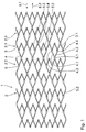
- Figure 1 shows a plan view of the development of the jacket 1 of a preferred Embodiment of a stent according to the invention with a number of annular Support sections 2.
- the development of the jacket 1 is in the first state of the stent shown in which it can be inserted into the blood vessel.
- the stent is there in the example shown exclusively from support sections 2, which are of meandering shape in the circumferential direction of the stent web elements 3 are formed.
- the Web elements 3 are connected to one another in the longitudinal direction of the stent via connecting webs 4 connected.
- the connecting webs 4 each engage in the area of turning points 5 of the Web elements 3.
- the stent consists exclusively of first support sections 2.1 and adjacent thereto in a first direction 6.1 second support sections 2.2.
- the connecting webs are arranged so that each two adjacent connecting webs 4.1 and 4.2 in the area of one in one second longitudinal direction 6.2 protruding turning point 5.1 of the second support section 2.2 attack.
- the second longitudinal direction 6.2 is the first longitudinal direction 6.1 opposite.
- the configuration is selected so that the first web element 3.1 and thus the first support section 2.1 adjacent first and has second turning points 5.2 and 5.3, in each of which a connecting web to a different turning point 5 of in the first direction 6.1 attacks adjacent second support section 2.2. Between these turning points 5.2 and 5.3 is a third turning point protruding in the second direction 6.2 5.4 arranged. In turn, reach in the area of this third turning point 5.4 two connecting webs to an adjacent one in the second longitudinal direction 6.2 Support section 2.3.
- This configuration results in a special one good distribution of the support points for the blood vessel to be supported.
- the web elements 3 are designed to increase the flexibility of the stent by their direction of curvature in the middle between two turning points 5 changes.
- This slightly S-shaped shape results in a lower rigidity of the web elements against forces acting in the longitudinal direction of the stent and thus a increased flexibility of the stent.
- the web elements 3 and the connecting webs 4 are still used to achieve a Stress distribution as uniform as possible during the deformation of the stent educated.
- a favorable voltage distribution is achieved on the one hand be that the width of the web element 3 - which is not shown in Figure 1 - decreases continuously towards the middle between two turning points 5.
- the decrease in thickness is about 50% in the example described. It determines itself however, with other designs of the web element depending on the other Geometry of the web element according to the stress limit to be observed in each case.
- the described width variation and the curvature of the web elements 3 and and the connecting web 4 also cause the tensions that occur in them during the expansion of the stent, above the elastic deformation limit and are below the fracture limit of the stent material.
- This effect can also be used to expand the stent, for example to change its position with respect to the blood vessel into one Envelope catheter corresponding to a small outside diameter in the first direction 6.1 to pull it in and thus, for example, to return it to its first state offset.
- This can be particularly advantageous in connection with a so-called use self-expanding stent.
- the stent has no sections projecting in the first direction 6.1, the a movement of the stent in the first direction 6.1 on the blood vessel or could get caught in such an enveloping catheter. It can thus be used during a movement of the stent in the first direction 6.1 does not come to a "fish scaling" effect.
- Figure 2 shows a plan view of the development of the jacket 1 'of a preferred Embodiment of a stent according to the invention with a number of annular Support sections 2 '.
- the development of the jacket 1 ' is in the first state of Stents shown in which it can be inserted into the blood vessel.
- the stent consists in the example shown exclusively of support sections 2 ', of Web elements 3 'running in a meandering shape in the circumferential direction of the stent are formed.
- the web elements 3 ' are in the longitudinal direction of the stent via connecting webs 4 'connected to each other.
- Figure 2 is the same in its basic structure and basic function of the variant of Figure 1, so that here only on the Differences to be addressed here in the arrangement of the connecting webs 4 lies over the stent
- first and second turning points 5.2' and 5.3' are one in the second 6.2 'protruding third turning point 5.4' arranged.
- this third turning point 5.4 'in turn two connecting webs engage in one the second longitudinal direction 6.2 'adjacent support section 2.3'.
- the stents are made in each case exclusively from meandering in the circumferential direction of the stent Web elements that are designed and arranged in the manner described.
- the stent also extends in sections in the longitudinal direction Support sections can exist, which are designed in a different way, in particular comprise differently designed web elements.
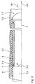
- FIG. 3 shows a schematic section through a catheter 7 for implantation of a stent 8 according to the invention from FIG. 1 with a distal end 7.1, in whose area is a casing device in the form of a casing tube 7.2 for receiving the Stents 8 is provided in its first state - shown in Figure 3.
- the Catheter 7 is inserted into a blood vessel 9.
- the catheter 7 has a displaceably arranged with respect to the sheath device 7.2 Device 7.3 for generating a relative movement between the casing device 7.2 and the stent 8 in the first longitudinal direction 6.1.
- the facility 7.3 has a holding device in the form of projections 7.4, which engage behind the web elements 3, so that a tensile force in the stent 8 first longitudinal direction 6.1 can be exercised.
- the facility also includes 7.3 a paragraph 7.5, on the stent 8, a compressive force in the second Longitudinal direction 6.2 can be exerted to remove the stent 8 from the sheath device 7.2 to slide out again.
- the holding device 7.4 held stent 8 in its first state. For example happen by the stent with the sheath 7.2 held through Moving the holding device 7.4 with respect to the sleeve device 7.2 into the latter is withdrawn, whereby it then passes through its leading edge 7.6 expanded diameter is forced to a reduced diameter.
- the stent 8 can also be held in place by the holding device 7.4 Position are held and the sleeve device 7.2 by means of a corresponding Device can be pushed over the stent 8.
- catheters 7 can be self-expanding as well as balloon-expandable Insert stents. Such a catheter is preferred with one provided stent according to the invention, in the sheath 7.2 of the catheter is arranged.
- the procedure for positioning a stent 8 in a vessel 9 is as follows become. This may involve positioning the stent in vivo as well also act in vitro, for example for testing purposes.
- the stent 8 is removed in a second step by at least partially removing it the sheath device 7.2 of the stent 8 is at least partially expanded.
- the position of the stent 8 with respect to the expansion site is checked detected. It can be provided that in the stent 8 in the second step is only partially expanded.
- the stent 8 then returned to its first state, in which it is then in the Envelope 8 is located, and then its position with respect to the expansion point changed.
- This correction step can also be repeated several times be before the stent 8 is finally completely expanded.
- the same principle of procedure can also be used with a balloon-expandable stent perform the first, if necessary over at least part of its length is brought up to the implantation site without a covering device and then under Use of a sheath is repositioned in the manner described above.
- the stent is brought into a third state, in which it is arranged in the casing.
- This third state can be the first State.
- the stent can also be compared to its own first state in a preferably partially expanded state, but also one still further compressed state.
Landscapes
- Health & Medical Sciences (AREA)
- Engineering & Computer Science (AREA)
- Biomedical Technology (AREA)
- Heart & Thoracic Surgery (AREA)
- Life Sciences & Earth Sciences (AREA)
- Cardiology (AREA)
- Oral & Maxillofacial Surgery (AREA)
- Transplantation (AREA)
- Physics & Mathematics (AREA)
- Vascular Medicine (AREA)
- Optics & Photonics (AREA)
- Animal Behavior & Ethology (AREA)
- General Health & Medical Sciences (AREA)
- Public Health (AREA)
- Veterinary Medicine (AREA)
- Media Introduction/Drainage Providing Device (AREA)
- Prostheses (AREA)
Abstract
Description
- Figur 1
- eine Draufsicht auf die Abwicklung des Mantels einer bevorzugten Ausführungsform des erfindungsgemäßen Stents;
- Figur 2
- eine Draufsicht auf die Abwicklung des Mantels einer weiteren bevorzugten Ausführungsform des erfindungsgemäßen Stents.
- Figur 3
- einen schematischen Schnitt durch einen auf einen Katheter angeordneten erfindungsgemäßen Stent.
Claims (11)
- Stent, insbesondere Koronarstent, zum Expandieren von einem ersten Zustand in einen aufgeweiteten zweiten Zustand, in dem er ein Gefäß aufgeweitet hält, mit einem rohrförmigen Körper, dessen Mantel (1; 1') von einer Anzahl ringförmiger Stützabschnitte (2, 2.1, 2.2, 2.3; 2', 2.1', 2.2'; 2.3') aus Stegelementen (3, 3.1, 3.2, 3.3; 3', 3.1', 3.2'; 3.3') gebildet ist, die in Längsrichtung des Stents über Verbindungsstege (4, 4.1, 4.2; 4') verbunden sind, wobei die Stegelemente (3, 3.1, 3.2, 3.3; 3', 3.1', 3.2'; 3.3') wenigstens eines ersten Stützabschnitts (2.1; 2.1') und eines in einer ersten Richtung (6.1; 6.1') benachbarten zweiten Stützabschnitts (2.2; 2.2') mäanderförmig in Umfangsrichtung des Stents verlaufen und im Bereich der in der ersten Richtung (6.1; 6.1') weisenden Wendepunkte (5.2, 5.3; 5.2', 5.3') des ersten Stützabschnitts die Verbindungsstege (4, 4.1, 4.2; 4') zum zweiten Stützabschnitt (2.2; 2.2') angreifen, dadurch gekennzeichnet, dass jeweils wenigstens zwei benachbarte Verbindungsstege (4.1, 4.2; 4.1', 4.2') im Bereich eines in einer zur ersten Richtung (6.1; 6.1') entgegengesetzten zweiten Richtung (6.2; 6.2') vorstehenden Wendepunktes (5.1; 5.1') des zweiten Stützabschnitts (2.2; 2.2') angreifen.
- Stent nach Anspruch 1, dadurch gekennzeichnet, dass genau zwei benachbarte Verbindungsstege (4.1, 4.2; 4.1', 4.2') im Bereich des in der zweiten Richtung (6.2; 6.2') vorstehenden Wendepunktes (5.1; 5.1') angreifen.
- Stent nach Anspruch 1 oder 2, dadurch gekennzeichnet, dass die Stegelemente (3.1, 3.2; 3.1', 3.2') des ersten und zweiten Stützabschnittes (2.1, 2.2; 2.1', 2.2') bezüglich der Umfangsrichtung des Stents miteinander im wesentlichen in Phase verlaufen.
- Stent nach einem der vorhergehenden Ansprüche, dadurch gekennzeichnet, dass der erste Stützabschnitt (2.1) im Umfangsrichtung des Stents benachbarte, in der ersten Richtung (6.1) vorragende erste und zweite Wendepunkte (5.2, 5.3) aufweist, in deren Bereich Verbindungsstege (4) zu unterschiedlichen Wendepunkten (5) des zweiten Stützabschnitts (2.2) angreifen und zwischen denen ein in der zweiten Richtung (6.2) vorragender dritter Wendepunkt (5.4) angeordnet ist, in dessen Bereich die beiden Verbindungsstege (4) eines in der zweiten Richtung (6.2) zu dem ersten Stützabschnitt benachbarten Stützabschnitts (2.3) mit mäanderförmig in Umfangsrichtung des Stents verlaufenden Stegelementen (3.3) angreifen.
- Stent nach einem der vorhergehenden Ansprüche, dadurch gekennzeichnet, dass die Stegelemente (3, 3.1, 3.2, 3.3; 3', 3.1', 3.2', 3.3') und/oder die Verbindungsstege (4, 4.1, 4.2; 4') zur Erhöhung der Flexibilität des Stents ausgebildet sind.
- Stent nach einem der vorhergehenden Ansprüche, dadurch gekennzeichnet, dass wenigstens ein Stützabschnitt (2, 2.1, 2.2, 2.3; 2', 2.1', 2.2'; 2.3') von einem Stegelement (3, 3.1, 3.2, 3.3; 3', 3.1', 3.2'; 3.3') gebildet ist, dessen Krümmungsrichtung sich im Mittenbereich zwischen zwei Wendepunkten (5) ändert und/oder wenigstens die Verbindungsstege (4, 4.1, 4,2; 4') zwischen dem ersten und zweiten Stützabschnitt (2.1, 2.2) einen gekrümmten Verlauf aufweisen, wobei sich ihre Krümmungsrichtung im Mittenbereich zwischen den beiden Angriffspunkten an den Stützabschnitten (2.1, 2.2) ändert.
- Stent nach einem der vorhergehenden Ansprüche, dadurch gekennzeichnet, dass die Stegelemente (3, 3.1, 3.2, 3.3; 3', 3.1', 3.2'; 3.3') und/oder die Verbindungsstege (4, 4.1, 4,2; 4') zur Erzielung einer möglichst gleichförmigen Spannungsverteilung bei der Verformung, insbesondere der Expansion des Stents ausgebildet sind.
- Stent nach einem der vorhergehenden Ansprüche, dadurch gekennzeichnet, dass wenigstens ein Stützabschnitt (2, 2.1, 2.2, 2.3; 2', 2.1', 2.2'; 2.3') von einem Stegelement (3, 3.1, 3.2, 3.3; 3', 3.1', 3.2'; 3.3') gebildet ist, dessen Breite zur Mitte zwischen zwei Wendepunkten (5) hin abnimmt, und/oder die Breite wenigstens der Verbindungsstege (4, 4.1, 4.2; 4') zwischen dem ersten und zweiten Stützabschnitt (2.1, 2.2; 2.1', 2.2') zur Mitte zwischen den beiden Angriffspunkten an den Stützabschnitten (2.1, 2.2; 2.1', 2.2') hin abnimmt.
- Stent nach einem der vorhergehenden Ansprüche, dadurch gekennzeichnet, dass wenigstens ein Stützabschnitt (2, 2.1, 2.2, 2.3; 2', 2.1', 2.2'; 2.3') von einem in Umfangsrichtung des Stents mäanderförmig verlaufenden Stegelement (3, 3.1, 3.2, 3.3; 3', 3.1', 3.2'; 3.3') gebildet ist, wobei je zwei in Umfangsrichtung des Stents benachbarte, zwischen den Wendepunkten (5) verlaufende Stegelementabschnitte die Schenkel eines Vbilden.
- Stent nach einem der vorhergehenden Ansprüche, dadurch gekennzeichnet, dassdass die Spannungen, die in ihnen bei der Expansion des Stents auftreten, oberhalb der elastischen Verformungsgrenze und unterhalb der Bruchgrenze des Stentwerkstoffs liegen.der Verlauf der Stegelemente (3, 3.1, 3.2, 3.3; 3', 3.1', 3.2'; 3.3') und/oder der Verbindungsstege (4, 4.1, 4.2; 4') derart gewählt ist und/oderdie Breite der Stegelemente (3, 3.1, 3.2, 3.3; 3', 3.1', 3.2'; 3.3') und/oder der Verbindungsstege (4, 4.1, 4.2; 4') derart über ihre Länge variiert,
- Katheter zur Stentimplantation mit einem Stent nach einem der vorhergehenden Ansprüche.
Applications Claiming Priority (2)
| Application Number | Priority Date | Filing Date | Title |
|---|---|---|---|
| DE10050940A DE10050940A1 (de) | 2000-10-10 | 2000-10-10 | Stent |
| DE10050940 | 2000-10-10 |
Publications (2)
| Publication Number | Publication Date |
|---|---|
| EP1197190A2 true EP1197190A2 (de) | 2002-04-17 |
| EP1197190A3 EP1197190A3 (de) | 2003-12-10 |
Family
ID=7659772
Family Applications (1)
| Application Number | Title | Priority Date | Filing Date |
|---|---|---|---|
| EP01250352A Withdrawn EP1197190A3 (de) | 2000-10-10 | 2001-10-08 | Stent |
Country Status (3)
| Country | Link |
|---|---|
| US (1) | US6796998B2 (de) |
| EP (1) | EP1197190A3 (de) |
| DE (1) | DE10050940A1 (de) |
Cited By (3)
| Publication number | Priority date | Publication date | Assignee | Title |
|---|---|---|---|---|
| EP2444033A4 (de) * | 2009-09-16 | 2012-11-28 | Terumo Corp | Stent zur platzierung in einem lebenden körper und stentverabreichungssystem |
| EP2497448A4 (de) * | 2009-12-28 | 2013-06-05 | Terumo Corp | Stentträgersystem |
| CN103945763A (zh) * | 2011-09-23 | 2014-07-23 | 奥索传感器公司 | 用于椎骨负载和位置感测的系统和方法 |
Families Citing this family (15)
| Publication number | Priority date | Publication date | Assignee | Title |
|---|---|---|---|---|
| AU2003256227A1 (en) * | 2002-07-30 | 2004-02-16 | Nanyang Technological University | Spherical nano-composite powder and a method of preparing the same |
| WO2004012743A1 (ja) * | 2002-08-01 | 2004-02-12 | Chugai Seiyaku Kabushiki Kaisha | 乾癬治療剤 |
| US20040054398A1 (en) * | 2002-09-13 | 2004-03-18 | Cully Edward H. | Stent device with multiple helix construction |
| DE10243136A1 (de) | 2002-09-17 | 2004-05-19 | Campus Medizin & Technik Gmbh | Stent zur Implantation in oder um ein Hohlorgan |
| GB0309616D0 (en) | 2003-04-28 | 2003-06-04 | Angiomed Gmbh & Co | Loading and delivery of self-expanding stents |
| GB0322511D0 (en) * | 2003-09-25 | 2003-10-29 | Angiomed Ag | Lining for bodily lumen |
| US20070250148A1 (en) * | 2005-09-26 | 2007-10-25 | Perry Kenneth E Jr | Systems, apparatus and methods related to helical, non-helical or removable stents with rectilinear ends |
| CN101732116B (zh) * | 2008-11-15 | 2014-04-16 | 上海微创医疗器械(集团)有限公司 | 用于病变血管修补的血管支架 |
| GB0901496D0 (en) | 2009-01-29 | 2009-03-11 | Angiomed Ag | Delivery device for delivering a stent device |
| GB0909319D0 (en) | 2009-05-29 | 2009-07-15 | Angiomed Ag | Transluminal delivery system |
| US9388127B2 (en) | 2012-04-17 | 2016-07-12 | University College Dublin, National University Of Ireland, Dublin | Thromboxane receptor antagonists |
| US9718781B2 (en) | 2012-04-17 | 2017-08-01 | University College Dublin, National University Of Ireland, Dublin | Methods and compounds for treating proliferative disorders and viral infections |
| ES2858551T3 (es) | 2015-06-16 | 2021-09-30 | Atxa Therapeutics Ltd | Antagonistas del receptor de tromboxano |
| JP2021153995A (ja) * | 2020-03-27 | 2021-10-07 | テルモ株式会社 | 生体内留置用ステントおよびステントデリバリーシステム |
| CN118924494A (zh) * | 2023-10-20 | 2024-11-12 | 北京新尖科技有限公司 | 瓣膜支架及瓣膜假体 |
Family Cites Families (10)
| Publication number | Priority date | Publication date | Assignee | Title |
|---|---|---|---|---|
| DE4418336A1 (de) * | 1994-05-26 | 1995-11-30 | Angiomed Ag | Stent |
| WO1997025937A1 (en) * | 1996-01-18 | 1997-07-24 | Jang G David | Programmable variably flexible modular stents |
| SG161732A1 (en) * | 1997-01-24 | 2010-06-29 | Nexeon Medsystems Inc | Expandable device having bistable spring construction |
| DE29708689U1 (de) | 1997-05-15 | 1997-07-17 | Jomed Implantate GmbH, 72414 Rangendingen | Koronarer Stent |
| DE29708879U1 (de) * | 1997-05-20 | 1997-07-31 | Jomed Implantate GmbH, 72414 Rangendingen | Koronarer Stent |
| DE19722384A1 (de) * | 1997-05-28 | 1998-12-03 | Gfe Ges Fuer Forschung Und Ent | Flexible expandierbare Gefäßstütze |
| US6042606A (en) * | 1997-09-29 | 2000-03-28 | Cook Incorporated | Radially expandable non-axially contracting surgical stent |
| DE19822157B4 (de) * | 1998-05-16 | 2013-01-10 | Abbott Laboratories Vascular Enterprises Ltd. | Radial aufweitbarer Stent zur Implantierung in ein Körpergefäß |
| US6355057B1 (en) * | 1999-01-14 | 2002-03-12 | Medtronic, Inc. | Staggered endoluminal stent |
| US6264685B1 (en) * | 1999-07-06 | 2001-07-24 | Datascope Investment Corp. | Flexible high radial strength stent |
-
2000
- 2000-10-10 DE DE10050940A patent/DE10050940A1/de not_active Withdrawn
-
2001
- 2001-10-08 EP EP01250352A patent/EP1197190A3/de not_active Withdrawn
- 2001-10-09 US US09/974,770 patent/US6796998B2/en not_active Expired - Lifetime
Cited By (5)
| Publication number | Priority date | Publication date | Assignee | Title |
|---|---|---|---|---|
| EP2444033A4 (de) * | 2009-09-16 | 2012-11-28 | Terumo Corp | Stent zur platzierung in einem lebenden körper und stentverabreichungssystem |
| US9314357B2 (en) | 2009-09-16 | 2016-04-19 | Terumo Kabushiki Kaisha | Stent for placement in living body and stent delivery system |
| EP2497448A4 (de) * | 2009-12-28 | 2013-06-05 | Terumo Corp | Stentträgersystem |
| CN103945763A (zh) * | 2011-09-23 | 2014-07-23 | 奥索传感器公司 | 用于椎骨负载和位置感测的系统和方法 |
| CN103945763B (zh) * | 2011-09-23 | 2016-04-06 | 奥索传感器公司 | 用于椎骨负载和位置感测的系统和方法 |
Also Published As
| Publication number | Publication date |
|---|---|
| US20020049494A1 (en) | 2002-04-25 |
| US6796998B2 (en) | 2004-09-28 |
| EP1197190A3 (de) | 2003-12-10 |
| DE10050940A1 (de) | 2002-04-11 |
Similar Documents
| Publication | Publication Date | Title |
|---|---|---|
| EP0983752B2 (de) | Stent | |
| EP1197190A2 (de) | Stent | |
| EP1070513B1 (de) | Ballonkatheter für Gefässabzweigungen | |
| EP1011534B1 (de) | Stent zur transluminalen implantation | |
| DE69613572T2 (de) | Vorrichtung zum einführen einer gefässprothese, die durch zurückziehen eines rohres diese prothese freigibt | |
| DE69725388T2 (de) | Katheter mit provisorischem vena-cava-Filter | |
| DE69121592T2 (de) | Resektierbarer selbstausbreitender stent | |
| DE69508592T2 (de) | Vorrichtung zur Stentimplantierung | |
| DE69934244T2 (de) | Spiralförmiger stent | |
| DE10105160B4 (de) | Implantierbare Gefäßstütze | |
| DE69525351T2 (de) | Weiche, flexible katheterspitze zur anwendung in der angiographie | |
| EP1184007A2 (de) | Spannungsoptimierter Stent | |
| DE19938377A1 (de) | Stent für Gefässverzweigungen | |
| DE102004012981B4 (de) | Stent | |
| EP1095632A2 (de) | Stent mit geschlossener Struktur | |
| DE10050970A1 (de) | Stent | |
| DE102012101284A1 (de) | Medizinische Vorrichtung mit einer Gitterstruktur und Behandlungssystem mit einer derartigen medizinischen Vorrichtung | |
| DE10012460A1 (de) | Stent | |
| DE202011107781U1 (de) | Prothesenanordnung zur Implantation in oder um ein Hohlorgan | |
| EP3010443A1 (de) | Stentgraft | |
| EP1197189A2 (de) | Stent | |
| EP4346707B1 (de) | Selbstexpandierender stent mit gestuftem radialkraftprofil | |
| EP1809203A1 (de) | Stützprothese | |
| EP2667831B1 (de) | Medizinische vorrichtung mit einer gitterstruktur und behandlungssystem mit einer derartigen vorrichtung | |
| DE8812719U1 (de) | Vorrichtung zum Beheben von Stenosen |
Legal Events
| Date | Code | Title | Description |
|---|---|---|---|
| PUAI | Public reference made under article 153(3) epc to a published international application that has entered the european phase |
Free format text: ORIGINAL CODE: 0009012 |
|
| AK | Designated contracting states |
Kind code of ref document: A2 Designated state(s): AT BE CH CY DE DK ES FI FR GB GR IE IT LI LU MC NL PT SE TR |
|
| AX | Request for extension of the european patent |
Free format text: AL;LT;LV;MK;RO;SI |
|
| PUAL | Search report despatched |
Free format text: ORIGINAL CODE: 0009013 |
|
| AK | Designated contracting states |
Kind code of ref document: A3 Designated state(s): AT BE CH CY DE DK ES FI FR GB GR IE IT LI LU MC NL PT SE TR |
|
| AX | Request for extension of the european patent |
Extension state: AL LT LV MK RO SI |
|
| 17P | Request for examination filed |
Effective date: 20040113 |
|
| AKX | Designation fees paid |
Designated state(s): AT BE CH CY DE DK ES FI FR GB GR IE IT LI LU MC NL PT SE TR |
|
| 17Q | First examination report despatched |
Effective date: 20050418 |
|
| GRAP | Despatch of communication of intention to grant a patent |
Free format text: ORIGINAL CODE: EPIDOSNIGR1 |
|
| RAP1 | Party data changed (applicant data changed or rights of an application transferred) |
Owner name: BIOTRONIK GMBH & CO. KG |
|
| STAA | Information on the status of an ep patent application or granted ep patent |
Free format text: STATUS: THE APPLICATION IS DEEMED TO BE WITHDRAWN |
|
| 18D | Application deemed to be withdrawn |
Effective date: 20061019 |