EP1197285A2 - Elektrische Schaltungsanordnung zur Erzeugung von Zündimpulsen für Schweisslichtbögen - Google Patents
Elektrische Schaltungsanordnung zur Erzeugung von Zündimpulsen für Schweisslichtbögen Download PDFInfo
- Publication number
- EP1197285A2 EP1197285A2 EP01123530A EP01123530A EP1197285A2 EP 1197285 A2 EP1197285 A2 EP 1197285A2 EP 01123530 A EP01123530 A EP 01123530A EP 01123530 A EP01123530 A EP 01123530A EP 1197285 A2 EP1197285 A2 EP 1197285A2
- Authority
- EP
- European Patent Office
- Prior art keywords
- charging
- charging current
- circuit
- ignition
- current source
- Prior art date
- Legal status (The legal status is an assumption and is not a legal conclusion. Google has not performed a legal analysis and makes no representation as to the accuracy of the status listed.)
- Withdrawn
Links
Images


Classifications
-
- B—PERFORMING OPERATIONS; TRANSPORTING
- B23—MACHINE TOOLS; METAL-WORKING NOT OTHERWISE PROVIDED FOR
- B23K—SOLDERING OR UNSOLDERING; WELDING; CLADDING OR PLATING BY SOLDERING OR WELDING; CUTTING BY APPLYING HEAT LOCALLY, e.g. FLAME CUTTING; WORKING BY LASER BEAM
- B23K9/00—Arc welding or cutting
- B23K9/06—Arrangements or circuits for starting the arc, e.g. by generating ignition voltage, or for stabilising the arc
- B23K9/067—Starting the arc
- B23K9/0672—Starting the arc without direct contact between electrodes
- B23K9/0673—Ionisation of the arc gap by means of pulsed or high-frequency voltages
Definitions
- Such a circuit arrangement is the subject of DE 198 44 273 A1.
- the circuit shown there has as a charging circuit, one constantly recharged by a rectifier Charging capacitor with downstream flyback converter circuit, through which an ignition capacitor with the charging capacitor is connectable.
- the discharge circuit formed by thyristors is controlled by a trigger circuit, the detects the electrical polarities of a welding circuit and generates a trigger signal when the polarity changes and thus according to the direction of the polarity change given thyristors turns on.
- the trigger circuit is furthermore via an optocoupler with a time circuit connected, the output of which is integrated as an input Circuit trained control of the flyback converter circuit connected is.
- the time cycle generates synchronous to Trigger signal a shutdown signal, which during a time period given by the characteristic of the time cycle is maintained.
- a shutdown signal As long as this shutdown signal is present, the flyback converter circuit holds the ignition capacitor electrically isolated from the charging capacitor. To this This ensures that the ignition capacitor only then can be recharged when the of the respective trigger signal conductive thyristors again their Have reached the locked state.
- control pulse transmitters are then synchronized with the welding alternating voltage trigger impulses to predetermined values Thyristors transferred, such that the primary winding an ignition pulse transmitter in one or the other Direction of the current of the discharging ignition capacitor is enforced and firing pulses of one or the other polarity induced on the secondary winding of the ignition pulse transmitter become.
- the object of the invention is now an improved control for creating the ignition pulses.
- This task is at the beginning of a circuit arrangement specified type solved in that the control too times depending on the parameters of the welding process after the trigger signal and / or the onset of the charging current, at the latest when the next trigger signal is generated, the shutdown signal to stop charging the ignition capacity turns.
- the invention is based on the general idea of charging the ignition capacity regardless of the time of the following Trigger signals for discharging the ignition capacity to be able to finish, depending on parameters of the welding process. As a result, performance or Energy of the ignition pulses controlled depending on the parameters.
- the time interval between the trigger signal and switch-off signal a measure of the state of charge of the ignition capacity.
- the charge current source is still cut low or disappearing output current of the Charging current source can be neglected in comparison to charging current become, i.e. this output current changes the state of charge the ignition capacity practically not and is from the optoelectric Transducer not detected.
- the charging circuit and the control are preferably separate from one another removed or arranged galvanically separated from each other, so that despite possibly extremely high voltage the ignition capacity and despite the inevitable high frequency Pulse amplitudes when the ignition capacity is discharged without further ado one designed for low electrical loads
- Control circuit in particular a digital control circuit with very low electrical power can, with which the additional advantage is achieved that usual Processors with high computing power and more diverse Programmability can be used for control.
- the invention switches or regulates the charging current source when reached an upper threshold of the electrical voltage Ignition capacity the charging current through automatic self-shutdown or self-regulation.
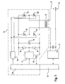
- a control unit 4 is assigned to the welding current source 1, the various parameters of the welding process, in particular the voltage between the welding outputs of the Welding current source and the strength of the respective welding current, can monitor and regulate. It also controls Control unit 4 in AC welding the AC frequency, which can also be changed depending on the parameters is, as well as the time and the measure of the current amplitude.
- a circuit arrangement 6 is assigned to generate ignition pulses.
- This circuit arrangement 6 has a switch-off signal switchable charging current source 7, which preferably is designed as a constant current source and one with it output capacitor 8 connected to a very can charge high electrical voltage.
- the charging current source 7 is designed such that it automatically switches off the charging current flowing to the ignition capacitor 8, as soon as a predetermined maximum charging voltage is reached is.
- a very high-resistance section with two resistors 9 arranged, which can have different dimensions. by virtue of the extremely high resistance of the resistance path these are only permeated by a negligible current. Between the resistors 9 is one compared to Voltage of the ignition capacitor 8 reduced voltage can be tapped, which are analogous to the electrical voltage of the Ignition capacitor 8 changes and from the charging current source 7 as Control signal for the aforementioned automatic shutdown of the charging current source 7 when the intended maximum voltage is reached of the ignition capacitor 8 is used.
- a bridge circuit is connected in parallel with the ignition capacitor 8 arranged with four thyristors 10 to 13, the each in pairs in two identical parallel branches of the bridge circuit connected in series in the same forward direction are.
- the thyristors 10 and 11 on the one hand and the thyristors 12 and 13 on the other hand is the primary side of the ignition pulse transmitter 5 connected.
- a trigger circuit is used to control the thyristors 10 to 13 14, with appropriate trigger pulses either thyristors 10 and 12 or thyristors 11 and 13 from the normal locked state (corresponding to an open Switch) in the conductive state (corresponding to a closed Switch) can switch.
- the charging current source 7 and the trigger circuit 14 is one Controller 15 associated with the control unit 4 of the Welding current source 1 communicates and thus essential parameters "knows" the welding process, especially the respective one electrical polarity of the welding outputs of the Welding current source 1 or the current direction of the welding current.
- controller 15 can control the essential parameters the welding process also via a separate sensor system "Experienced".
- the controller 15 controls the trigger circuit 14, i.e. the Controller 15 determines the time and type of the trigger circuit 14 trigger pulses. So determined in the result the controller 15, which of the thyristors 10 to 13 when be switched to the conductive state.
- the charging current source 7 can be controlled by the controller 15 switched off by a practically power-free control signal or be curtailed.
- the charging current source has 7 a corresponding control input. If such a shutdown signal is present, switches or regulates the charging current source 7 decreases or remains limited or off. If there is no shutdown signal, generated the charging current source 7 a charging the ignition capacitor 8 Charging current, provided that the maximum charging voltage of the ignition capacitor 8 has not yet been reached.
- the controller 15 detects whether a charging current to Ignition capacitor 8 flows or not, with "none” in the state Charging current ", possibly from the charging current source 7 very low or vanishing, not detected by the converter 16 Output current can be generated.
- the controller 15 can use an internal clock time duration of the ignition capacitor 8 after a discharge Detect supplied charging currents and "knows" the State of charge of the ignition capacitor 8.
- the charging current source 7 has the characteristic of a constant current source the charge of the ignition capacitor 8 is linear with the charging time. If the charging current source 7 is one of a constant current source has different characteristics, the Control 15 take this characteristic into account, for example by time-dependent weighting factors, if the state of charge of the ignition capacitor 8 can be detected exactly should.
- the controller 15 can be used for maximum charging of the ignition capacitor 8 determine the required period of time, see above that subsequently with shorter loading times, as with accordingly earlier generation of the shutdown signals of the control 15 occur, the ratio of the charge actually reached to the maximum charge analogous to the ratio of the actual Charging time and the time required for a maximum charge Charging time is.
- the ignition capacitor 8 is from the charging current source 7 loaded.
- the controller 15 recognizes the point in time and polarity of an ignition pulse to be generated by communication with the control unit 4. As soon as an ignition pulse is generated the controller 15 controls the trigger circuit 14 with a corresponding trigger signal, such that either the thyristors 10 and 12 or the thyristors 11 and 13 are brought into the conductive state. This causes the ignition capacitor 8 to discharge, whereby the discharge current depending on the respective conductive Thyristors 10 and 12 or 11 and 13 in one or the primary side of the ignition pulse transmitter 5 in the other direction interspersed. Accordingly, in the secondary side of the Ignition pulse transmitter 5 an ignition pulse with one or of the other polarity.
- the Controller 15 the switch-off signal for charging current source 7, to prevent the charging current source 7 in addition to Ignition capacitor 8 a the primary side of the ignition pulse transmitter 5 can generate larger current.
- the charging current source 7 is switched off after discharge of the ignition capacitor 8 ensures with certainty that the Thyristors previously switched on by trigger signals 10 and 12 or 11 and 13 automatically in their locked state pass.
- the ignition capacitor is used for a subsequent ignition pulse 8 reloaded.
- the shutdown signal is switched off or left off and depending on parameters predeterminable time switched on again, if necessary only when generating a trigger signal for the trigger circuit 14th
- the controller 15 By galvanically decoupling the controller 15 from the charging circuit of the ignition capacitor 8 can if necessary extremely high charging voltages of the ignition capacitor 8 and the high-frequency pulse amplitudes when the ignition pulse is triggered or discharge current of the ignition capacitor 8 practically have no repercussions on the controller 15. As a result this ensures that the controller 15 as a microelectronic digital circuit can be formed wherein one or more processors for the circuit construction with high operating speeds and extensive programmability can be used.
- controller 15 can also be part of the control unit 4 of the welding power source.
- the clocked charging current source shown as an example in FIG. 2 7 has a control 15 on the input side connected PWM generator, which by means of pulse width modulated Output signals alternate between two semiconductor switches 71.72 controls, so that the semiconductor switch alternately 71 and the semiconductor switch 72 electrically permeable to current become.
- the aforementioned ladder switches 71 and 72 become primary winding branches 73 and 74 of a transformer or transformer alternately with the connections 75 and 76 for the electrical supply voltage of the charging current source 7 connected so that in the secondary winding 77 a surge of one or the other polarity is generated.
- the secondary winding is connected via a rectifier 78 77 connected to the ignition capacitor 8.
- setpoint signals i setpoint and u setpoint are generated within the charging current source 7 for the current strength of the charging current and the final value of the voltage of the ignition capacitor.
- the current command signal i target with the delivered by a corresponding sensor current actual value signal i is compared.
- a signal 17 correlated with the setpoint / actual value difference of the charging current can thus be supplied to a controller 17.
- the voltage setpoint signal u Soll is compared with the voltage actual value signal u Ist tapped between the resistors 9, so that the controller 17 can be supplied with a signal correlated with the setpoint-actual value difference in the voltage of the ignition capacitor 8.
- controller 17 may receive this from the Control 15 generated shutdown signal A.
Landscapes
- Engineering & Computer Science (AREA)
- Physics & Mathematics (AREA)
- Plasma & Fusion (AREA)
- Mechanical Engineering (AREA)
- Generation Of Surge Voltage And Current (AREA)
- Arc Welding Control (AREA)
Abstract
Description
- einer Zündkapazität, insbesondere einem Zündkondensator,
- einer damit über einen Ladestromkreis elektrisch verbundenen, durch Abschaltsignal abschaltbaren bzw. auf vernachlässigbaren Ausgangsstrom abregelbaren Ladestromquelle, die bei fehlendem Abschaltsignal und/oder bei Unterschreitung eines Schwellwertes der elektrischen Spannung der Zündkapazität einen Ladestrom zur Zündkapazität leitet,
- einer durch Auslösesignal auslösbaren Entladeschaltung, über die die Zündkapazität unter Einkopplung ihres Entladestromes in einen Schweißausgang eines Schweißgerätes entladbar ist, und
- einer gegenüber Rückwirkungen vom Ladestromkreis bzw. Entladestrom geschützten bzw. sicheren Steuerung, die in Abhängigkeit von vorgegebenen Parametern eines Schweißprozesses das Auslösesignal erzeugt.
- Fig. 1
- einen schematisierten Schaltplan der erfindungsgemäßen Schaltungsanordnung mit Steuerung und zugehörigem Schweißgerät,
- Fig. 2
- ein Beispiel einer getakteten Ladestromquelle und
- Fig. 3
- ein Beispiel einer Regelung der Ladestromquelle.
Claims (8)
- Elektrische Schaltungsanordnung zur Erzeugung von Zündimpulsen für Schweißlichtbögen, mitdadurch gekennzeichnet, daß die Steuerung (15) zu von den Parametern des Schweißprozesses abhängigen Zeitpunkten nach dem Auslösesignal und/oder dem Einsetzen des Ladestromes, spätestens bei Erzeugung des nächstfolgenden Auslösesignales, zur Beendigung der Aufladung der Zündkapazität (8) das Abschaltsignal einschaltet.einer Zündkapazität (8),einer damit über einen Ladestromkreis elektrisch verbundenen, durch Abschaltsignal abschaltbaren oder auf vernachlässigbaren Ausgangsstrom abregelbaren Ladestromquelle (7), die bei fehlendem Abschaltsignal und/oder Unterschreitung eines Schwellwertes der elektrischen Spannung der Zündkapazität (8) einen Ladestrom zur Zündkapazität (8) leitet,einer durch Auslösesignal auslösbaren Entladeschaltung (1o bis 13), über die die Zündkapazität (8) unter Einkopplung ihres Entladestromes in einen Schweißausgang eines Schweißgerätes (1 bis 3) entladbar ist, undeiner gegenüber Rückwirkungen vom Ladestromkreis bzw. Entladestrom geschützten bzw. sicheren Steuerung (15), die in Abhängigkeit von vorgegebenen Parametern eines Schweißprozesses das Auslösesignal erzeugt,
- Schaltungsanordnung nach Anspruch 1,
dadurch gekennzeichnet, daß die Ladestromquelle (7) bei Erreichen eines oberen Schwellwertes der elektrischen Spannung des Zündkondensators (8) den Ladestrom durch automatische Selbstabschaltung regelt. - Schaltungsanordnung nach Anspruch 2,
dadurch gekennzeichnet, daß die Steuerung (15) jeweils bei Betriebsbeginn bzw. vorgebbaren Betriebsphasen vor Erzeugung eines Abschaltsignales die Zeit bis zur automatischen Selbstabschaltung der Ladestromquelle (7) als maximale Ladezeit registriert bzw. speichert und nachfolgend die auf ein Einsetzen des Ladestromes folgenden Abschaltsignale jeweils nach einem Zeitintervall erzeugt, welches gegenüber der maximalen Ladezeit um einen durch die Parameter vorgegebenen Anteil verkürzt ist. - Schaltungsanordnung nach einem der Ansprüche 1 bis 3,
dadurch gekennzeichnet, daß die Ladestromquelle (7) als Konstantstromquelle ausgebildet ist. - Schaltungsanordnung nach einem der Ansprüche 1 bis 4,
dadurch gekennzeichnet, daß die Ladestromquelle (7) einen gepulsten Ladestrom erzeugt. - Schaltungsanordnung nach einem der Ansprüche 1 bis 5,
dadurch gekennzeichnet, daß die Steuerung (5) gegenüber Rückwirkungen des Ladestromkreises bzw. Entladestromes durch Entfernung oder galvanische Trennung vom Ladestromkreis geschützt ist. - Schaltungsanordnung nach einem der Ansprüche 1 bis 6,
dadurch gekennzeichnet, daß die Steuerung (15) als programmierbare, digitale, mikroelektronische Steuerung ausgebildet ist. - Schaltungsanordnung nach einem der Ansprüche 1 bis 7,
dadurch gekennzeichnet, daß am Ladestromkreis ein optoelektrischer Wandler (16) angeordnet ist, dessen vom Ladestromkreis galvanisch getrennter Signalausgang mit der Eingangsseite der Steuerung (15) verbunden ist und Signale überträgt, die oberhalb und unterhalb eines geringen Schwellwertes des Ladestroms unterschiedlich sind.
Applications Claiming Priority (2)
| Application Number | Priority Date | Filing Date | Title |
|---|---|---|---|
| DE2000150923 DE10050923C2 (de) | 2000-10-13 | 2000-10-13 | Elektrische Schaltungsanordnung zur Erzeugung von Zündimpulsen für Schweisslichtbögen |
| DE10050923 | 2000-10-13 |
Publications (2)
| Publication Number | Publication Date |
|---|---|
| EP1197285A2 true EP1197285A2 (de) | 2002-04-17 |
| EP1197285A3 EP1197285A3 (de) | 2003-05-28 |
Family
ID=7659762
Family Applications (1)
| Application Number | Title | Priority Date | Filing Date |
|---|---|---|---|
| EP01123530A Withdrawn EP1197285A3 (de) | 2000-10-13 | 2001-09-29 | Elektrische Schaltungsanordnung zur Erzeugung von Zündimpulsen für Schweisslichtbögen |
Country Status (2)
| Country | Link |
|---|---|
| EP (1) | EP1197285A3 (de) |
| DE (1) | DE10050923C2 (de) |
Cited By (4)
| Publication number | Priority date | Publication date | Assignee | Title |
|---|---|---|---|---|
| WO2005051585A1 (de) * | 2003-11-25 | 2005-06-09 | Fronius International Gmbh | Verfahren und schaltung zum berührungslosen zünden eines schweisslichtbogens mit hochfrequenten zündimpulspaketen |
| US6948888B2 (en) | 2002-12-27 | 2005-09-27 | Eisenmann Maschinenbau Kg (Komplementar:Eisenmann-Shiftung) | Reservoir for powdery media |
| EP1882541B1 (de) * | 2006-07-28 | 2009-12-09 | Lorch Schweisstechnik GmbH | Impulsgenerator einer elektrischen Schweissstromquelle |
| CN104942403A (zh) * | 2015-07-23 | 2015-09-30 | 深圳华意隆电气股份有限公司 | 市电同步50hz高压脉冲引弧装置 |
Family Cites Families (4)
| Publication number | Priority date | Publication date | Assignee | Title |
|---|---|---|---|---|
| DE3011127A1 (de) * | 1980-03-22 | 1981-10-01 | Ernst G. 5203 Much Trost | Schaltungsanordnung zum erzeugen von zuendimpulsen fuer wechselstrom- oder gleichstrom-schweisslichtboegen |
| DE3049133A1 (de) * | 1980-12-24 | 1982-07-15 | Ernst G. 5203 Much Trost | Schaltungsanordnung zum zuenden von gleichstromschweisslichtboegen, sowie zum zuenden und stabilisieren eines wechselstromschweisslichtbogens |
| JP3369345B2 (ja) * | 1995-02-16 | 2003-01-20 | ポップリベット・ファスナー株式会社 | スタッド溶接機 |
| DE19844273C2 (de) * | 1998-09-26 | 2001-09-20 | Egt Ind Elektronik Gmbh | Elektronisches Zündgerät |
-
2000
- 2000-10-13 DE DE2000150923 patent/DE10050923C2/de not_active Expired - Fee Related
-
2001
- 2001-09-29 EP EP01123530A patent/EP1197285A3/de not_active Withdrawn
Cited By (7)
| Publication number | Priority date | Publication date | Assignee | Title |
|---|---|---|---|---|
| US6948888B2 (en) | 2002-12-27 | 2005-09-27 | Eisenmann Maschinenbau Kg (Komplementar:Eisenmann-Shiftung) | Reservoir for powdery media |
| WO2005051585A1 (de) * | 2003-11-25 | 2005-06-09 | Fronius International Gmbh | Verfahren und schaltung zum berührungslosen zünden eines schweisslichtbogens mit hochfrequenten zündimpulspaketen |
| US7638734B2 (en) | 2003-11-25 | 2009-12-29 | Fronius International Gmbh | Method and circuit for contactless ignition of a welding arc with high frequency ignition pulse packets |
| CN1886225B (zh) * | 2003-11-25 | 2010-10-06 | 弗罗纽斯国际有限公司 | 由高频引燃脉冲群非接触式引燃焊弧的方法和电路 |
| EP1882541B1 (de) * | 2006-07-28 | 2009-12-09 | Lorch Schweisstechnik GmbH | Impulsgenerator einer elektrischen Schweissstromquelle |
| CN104942403A (zh) * | 2015-07-23 | 2015-09-30 | 深圳华意隆电气股份有限公司 | 市电同步50hz高压脉冲引弧装置 |
| CN104942403B (zh) * | 2015-07-23 | 2016-09-28 | 深圳华意隆电气股份有限公司 | 市电同步50Hz高压脉冲引弧装置 |
Also Published As
| Publication number | Publication date |
|---|---|
| DE10050923C2 (de) | 2003-04-30 |
| DE10050923A1 (de) | 2002-04-25 |
| EP1197285A3 (de) | 2003-05-28 |
Similar Documents
| Publication | Publication Date | Title |
|---|---|---|
| EP0268109B1 (de) | Impulsgenerator zur funkenerosiven Metallbearbeitung | |
| DE102005055160B4 (de) | Regelschaltung zur Strom- und Spannungregelung in einem Schaltnetzteil | |
| DE3743310C2 (de) | ||
| DE102010045168B4 (de) | Zündanlage und Verfahren zum Zünden von Brennstoff in einem Fahrzeugmotor durch eine Koronaentladung | |
| WO1992022120A1 (de) | Verfahren zum vorzugsweisen schnellen laden von wiederaufladbaren batterien | |
| EP3224950B1 (de) | Verfahren und vorrichtung zum ansteuern parallel geschalteter leistungshalbleiterschalter | |
| EP0186865B1 (de) | Vorrichtung zur Unterbrechung von bogenförmigen Entladungen in einem Gasentladungsgefäss | |
| EP1149455B1 (de) | Verfahren und vorrichtung zum laden von akkumulatoren | |
| DE2924170A1 (de) | Kondensator-stromversorgung fuer elektrische bearbeitung | |
| DE2824326A1 (de) | Stromversorgung fuer elektrische bearbeitung | |
| DE69315322T2 (de) | Freilaufendes kapazitives entladungszündsystem mit zündfunkenfrequenzsteuerung | |
| DE3708071A1 (de) | Energieversorgungsvorrichtung, insbesondere fuer eine gasentlandungsvorrichtung | |
| DE3508289C1 (de) | Wechselrichter zur Speisung eines Verbrauchers mit einer induktiven Komponente | |
| DE830522C (de) | Schaltung zur Erzeugung eines durch einen Steuerimpuls ausgeloesten Hochfrequenz-Leistungs-Impulses | |
| DE2167212C2 (de) | Schaltungsanordnung zur Erzeugung wenigstens einer vorgegebenen Ausgangsspannung, deren Größe von einer Eingangsspannung unabhängig ist | |
| EP1197285A2 (de) | Elektrische Schaltungsanordnung zur Erzeugung von Zündimpulsen für Schweisslichtbögen | |
| EP0971567A1 (de) | Plasmalichtbogeneinrichtung | |
| DE1298853B (de) | Verfahren zur Energieversorgung von Funkenerosionsanlagen | |
| DE2713045C3 (de) | Schweißstromquelle | |
| EP1825529B1 (de) | Elektrische schaltung zur ansteuerung eines piezoelektrischen elements insbesondere einer kraftstoffeinspritzanlage eines kraftfahrzeugs | |
| DE3238899A1 (de) | Kurzschlussfeste ansteuerschaltung fuer einen elektrischen verbraucher | |
| EP2991224B1 (de) | Stoßstromgenerator | |
| DE2634396C2 (de) | Blitzeinrichtung | |
| DE3116447A1 (de) | "impulsgenerator" | |
| EP2675037A1 (de) | Betriebssteuervorrichtung und Verfahren zur Steuerung des Betriebs einer Beleuchtungsanordnung mit Notbeleuchtung |
Legal Events
| Date | Code | Title | Description |
|---|---|---|---|
| PUAI | Public reference made under article 153(3) epc to a published international application that has entered the european phase |
Free format text: ORIGINAL CODE: 0009012 |
|
| AK | Designated contracting states |
Kind code of ref document: A2 Designated state(s): AT BE CH CY DE DK ES FI FR GB GR IE IT LI LU MC NL PT SE TR |
|
| AX | Request for extension of the european patent |
Free format text: AL;LT;LV;MK;RO;SI |
|
| PUAL | Search report despatched |
Free format text: ORIGINAL CODE: 0009013 |
|
| AK | Designated contracting states |
Designated state(s): AT BE CH CY DE DK ES FI FR GB GR IE IT LI LU MC NL PT SE TR |
|
| AX | Request for extension of the european patent |
Extension state: AL LT LV MK RO SI |
|
| AKX | Designation fees paid | ||
| REG | Reference to a national code |
Ref country code: DE Ref legal event code: 8566 |
|
| STAA | Information on the status of an ep patent application or granted ep patent |
Free format text: STATUS: THE APPLICATION IS DEEMED TO BE WITHDRAWN |
|
| 18D | Application deemed to be withdrawn |
Effective date: 20031129 |