EP1197621A1 - Dispositif de verrouillage pour coffre de rangement - Google Patents
Dispositif de verrouillage pour coffre de rangement Download PDFInfo
- Publication number
- EP1197621A1 EP1197621A1 EP01124192A EP01124192A EP1197621A1 EP 1197621 A1 EP1197621 A1 EP 1197621A1 EP 01124192 A EP01124192 A EP 01124192A EP 01124192 A EP01124192 A EP 01124192A EP 1197621 A1 EP1197621 A1 EP 1197621A1
- Authority
- EP
- European Patent Office
- Prior art keywords
- handle
- locking
- locking hook
- spring
- frame part
- Prior art date
- Legal status (The legal status is an assumption and is not a legal conclusion. Google has not performed a legal analysis and makes no representation as to the accuracy of the status listed.)
- Granted
Links
- 238000013016 damping Methods 0.000 claims description 7
- 230000006835 compression Effects 0.000 claims description 4
- 238000007906 compression Methods 0.000 claims description 4
- 230000006870 function Effects 0.000 claims 2
- 230000016776 visual perception Effects 0.000 claims 1
- 238000010276 construction Methods 0.000 description 4
- 238000000034 method Methods 0.000 description 3
- 230000007547 defect Effects 0.000 description 1
- 238000011161 development Methods 0.000 description 1
- 230000018109 developmental process Effects 0.000 description 1
- 230000000284 resting effect Effects 0.000 description 1
- 239000000725 suspension Substances 0.000 description 1
Images


Classifications
-
- B—PERFORMING OPERATIONS; TRANSPORTING
- B64—AIRCRAFT; AVIATION; COSMONAUTICS
- B64D—EQUIPMENT FOR FITTING IN OR TO AIRCRAFT; FLIGHT SUITS; PARACHUTES; ARRANGEMENT OR MOUNTING OF POWER PLANTS OR PROPULSION TRANSMISSIONS IN AIRCRAFT
- B64D11/00—Passenger or crew accommodation; Flight-deck installations not otherwise provided for
- B64D11/003—Stowage devices for passengers' personal luggage
-
- E—FIXED CONSTRUCTIONS
- E05—LOCKS; KEYS; WINDOW OR DOOR FITTINGS; SAFES
- E05B—LOCKS; ACCESSORIES THEREFOR; HANDCUFFS
- E05B5/00—Handles completely let into the surface of the wing
-
- E—FIXED CONSTRUCTIONS
- E05—LOCKS; KEYS; WINDOW OR DOOR FITTINGS; SAFES
- E05C—BOLTS OR FASTENING DEVICES FOR WINGS, SPECIALLY FOR DOORS OR WINDOWS
- E05C3/00—Fastening devices with bolts moving pivotally or rotatively
- E05C3/12—Fastening devices with bolts moving pivotally or rotatively with latching action
- E05C3/16—Fastening devices with bolts moving pivotally or rotatively with latching action with operating handle or equivalent member moving otherwise than rigidly with the latch
-
- E—FIXED CONSTRUCTIONS
- E05—LOCKS; KEYS; WINDOW OR DOOR FITTINGS; SAFES
- E05B—LOCKS; ACCESSORIES THEREFOR; HANDCUFFS
- E05B41/00—Locks with visible indication as to whether the lock is locked or unlocked
Definitions
- the invention relates to a detachable mechanical Locking arrangement between a pivotable cover and a container, preferably a luggage compartment.
- connection arrangements are known from the prior art: Arrangements similar to door locks to be operated with keys, snap locks, snap locks, etc.
- European patent specification (application number 93309559.8; publication number 0634549 A1) describes a self-closing lock which has a handle which can be pivoted in a housing (frame). The handle can assume two positions: an unlocked and a locked position.
- This lock includes, inter alia, a cam lever which can be actuated by the handle and can be pivoted about a first axis, a locking slide which can be displaced along a second axis (perpendicular to the first axis) and one along a third axis (perpendicular to the second axis) Movable lock part as well as a number of other parts which, in cooperation, determine the two positions of the handle.
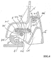
- Such a locking arrangement for a pivoting luggage compartment lid is described, for example, in German utility model 29 808 914.9 (see FIG. 4): It comprises a frame part 1 'connected to a cover and a pivotable handle 2' arranged in this frame part 1 '.
- a locking hook locking lug 8 'connected to the luggage compartment can be locked by a locking hook 3'.
- the handle 2 ' is pivotable about a handle pivot axis HA ⁇ arranged in the frame part 1'.
- the locking hook 3 ' is pivotable about a locking hook pivot axis VA' arranged in the frame part 1 ', which runs parallel to the handle pivot axis HA'.
- a connecting member 5 ' Between the handle 2 'and the locking hook 3' there is a connecting member 5 ', the handle (2') near end of which is connected to a first connecting member pivot axis CA 'arranged in the handle 2' and the handle (2 ') distal end with an elongated hole-like Recess 5-2 'is provided, through which a second link pivot axis 7-1' of the locking hook 3 'runs parallel to the first link pivot axis CA'.
- a compression spring 7-2 'acting between the first CA' and the second 7-1 'link pivot axis 7-1' is arranged on the link 5 '.
- the handle 2 ' can be pivoted into the frame part 1' by a spring 4 'arranged between it and the frame part 1'.
- the second link pivot axis 7-1 ' is arranged in the position (5') of the recess 5-2 'in the handle (2'), the force of the spring 4 'exceeding that of the compression spring 7-2' and the handle 2 'is pivoted into the frame part. If the lock is not fully closed, in the event of the locking hook 3 'not being locked on the locking hook, or in the case of an object (e.g.
- the handle 2 ' is such by the compression spring 7 -2 'pivoted against the force of the spring 4' from the frame part 1 'so that it partially protrudes from the outer surface plane of the frame part 1'.
- This construction eg 2 axes are required
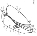
- FIG.1 shows is a schematic perspective view of the frame part 1 and the handle 2 in the not fully closed position PO.
- the phrase "not completely closed position" PO means that the front surface F of the handle 2 protrudes from the continuously imagined surface area F 'of the frame part 1 (in such a case, the front surface F of the handle 2 intersects the continuously imagined front surface F' of the frame part 1 ). Locking has not yet taken place in such a position (an almost not yet fully closed hinged lid). Such a position must be easily recognizable for security reasons.
- the handle 2 can manually by engaging in a Handle recess 2-1 (FIG. 2A, FIG. 2B) in direction A from the Frame part 1 can be pivoted out.
- the pivoting takes place via two lever arms 6 and 6 * connected to the handle.
- lever arms sit on a handle pivot axis HA or HA *, which is connected to the frame part 1 (see FIG. 2A and 2B).
- the handle 2 can be closed in the direction B by pressing its front surface F. Except in an exceptional case (which will be discussed later), the locking arrangement is also locked.
- the front surface F of the handle 2 lies in the imaginary front surface F 'of the frame part, ie the frame surfaces F and F' are "aligned" with one another.
- the front surfaces F and F ' lie at an angle to one another: when looking in the direction Z, the side surface S of the handle 2 can be seen (it can be highlighted in red to emphasize it); it immediately signals to the viewer that PO of the handle 2 is not completely closed.
- Such a not fully closed position means that the locking arrangement is not locked.
- the openings 1-1, 1-2, 1-3 and 1-4 in the frame part 1 serve the Fixing the same in a frame, e.g. in the flap of one Luggage compartment on the plane.
- each swivel arm 6 and 6 * and 3 * There is a locking hook 3 next to each swivel arm 6 and 6 * and 3 * arranged. These locking hooks 3 and 3 * are like the swivel arms 6 and 6 * on the handle swivel axes HA or HA * pivotally arranged.
- Locking hooks one each inside the container (not shown) arranged locking closure part at the edge (analogous to the locking locking lug shown in FIG. 4; just as well e.g. also a shaft as a locking closure part be provided).
- the handle 2 can be pivoted into the frame part by at least one swivel arm spring (not shown) arranged between the latter and the frame part 1.
- a swivel arm spring is preferably designed as a torsion coil spring and arranged on the handle axis HA, with its ends being supported on the swivel arm 6 of the handle and on the frame part 1.
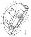
- FIG.2 A and FIG. 2B show schematic perspective views of the back of the frame part 1 and the handle 2 with a view of the locking hooks 3 and 3 * and the swivel arms 6 and 6 * of the handle 2nd
- Locking hook 3 and swivel arm 6 sit on the handle pivot axis HA common to them; Locking hook 3 * and swivel arm 6 * sit on the common handle swivel axis HA *.
- the handle swivel axes HA and HA * are aligned. These pivot axes are fixed in the side walls of the hollow recesses 4 and 4 * of the frame part 1. These hollow niches are open at the bottom for the exit of the swivel arms and locking hooks.
- the locking hooks 3 and 3 * each have a hook pit 3-1, 3-1 * on. Sitting in the locked position Hook pits the locking hook closure parts, not shown (e.g. nose or rod-shaped structures). she are locked by the locking hook.
- the locking hook has at its head end a projection 3-2 which, when the locking hook 3 moves in the Y direction, strikes the driver 5 arranged on the handle 2 and stops the movement. The movement can also be stopped by another stop (e.g. on the hollow niche).
- the driver 5 is used in particular for the fact that when the locking arrangement is opened (handle is pulled / pivoted in direction A) the locking hook is pulled by the driver 5 from the locking hook closure part (not shown).
- a spring 9 and 9 * is attached, which serves to "cushion" the handle when the locking hook and handle are moved towards each other.
- a correspondingly designed locking hook or an element connected to it would strike the inside (2-2) of the handle (2) and, when the locking hook is pivoted further, the handle (2) from the closed to the open position (PO) move.
- the locking hook 3 * can be pivoted in the unlocked state in the opening direction A of the handle until the spring 9 * connected to it strikes the inside 2-2 of the handle 2 (FIG. 3).
- the handle 2 is moved by the spring 9 * acting on it from its closed position against increasing spring (9 *) force into the open position PO.
- the handle 2 is pressed in the locking direction when the position PO is not completely closed, the exception may occur that locking is not possible. This exception is given, for example, if an item of clothing is undesired on the locking hook closure part and prevents locking.
- the end 9-1 * of the spring 9 * would be pressed against the inner wall 2-2 of the handle when the locking hook is pivoted (FIG. 3). The more handle and locking hook are moved towards each other, the higher the counteracting spring force.
- the handle is "cushioned" when an impossible lock is to be forced. In this way, the risk of damage to the locking arrangement or the disruptive garment is avoided or reduced.
- FIG.3 shows a partially schematic perspective view of the back of the frame part 1 and the handle 2 in the closed position of the handle with a view of the locking hook 3 *.
- the reference numerals for the corresponding parts are the same as in FIG. 2A and 2B.
- FIG. 3 is used for a more detailed representation of the spring 9 * when its base end 9-1 * is pressed against the inner wall 2-2 of the handle (dashed contact area) and resiliently deviates in the direction of T with increasing pressure (with a "gentle increase in spring force) , If no locking can take place during this process, the risk of damage to the parts involved in the closing process is prevented or at least reduced.
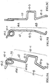
- FIG. 5 shows A-5C a combination spring 10 in different views.
- This combination spring 10 combines the function of the swivel arm spring (not shown) and the function of the damping spring 9, 9 *.
- the combination spring 10 has, inter alia, a spring arm (10 C) comprising two sections (10-A, 10-B). Your turn 10-1 would have to be arranged on the handle axis HA or HA ', with the part 10-2 being supported on the frame part.
- the end 10-AE of its section 10-A which is close to the axis, should lie against the swivel arm and pretension it to achieve the closed position of the handle.
- the section 10 B remote from the axis has a meandering section 10-3 resting on the locking hook and a free arm end 10-4 (comparable in function to that of the damping spring 9), which increasingly cushions the pivoting locking hook against the inner wall of the handle 2, when the locking hook and the inner wall of the handle come closer to each other.
- the holes in the locking hook for receiving the ends for the damping spring 9 can be omitted.
- the compact construction of the locking arrangement according to the invention makes it possible to provide two independently acting locking hooks 3, 3 * on the frame part 1. This provides the possibility of a so-called double locking. If only one of the two locking hooks can be locked (while the other cannot be locked due to an assumed defect or due to an item of clothing that interferes with the locking process), a simple (not double) locking is still guaranteed.
Landscapes
- Engineering & Computer Science (AREA)
- Aviation & Aerospace Engineering (AREA)
- Mechanical Engineering (AREA)
- Purses, Travelling Bags, Baskets, Or Suitcases (AREA)
- Closures For Containers (AREA)
Applications Claiming Priority (2)
| Application Number | Priority Date | Filing Date | Title |
|---|---|---|---|
| DE20017674U DE20017674U1 (de) | 2000-10-14 | 2000-10-14 | Lösbare mechanische Verriegelungsanordnung zwischen einem schwenkbaren Deckel und einem Behälter, vorzugsweise einem Gepäckfach |
| DE20017674U | 2000-10-14 |
Publications (2)
| Publication Number | Publication Date |
|---|---|
| EP1197621A1 true EP1197621A1 (fr) | 2002-04-17 |
| EP1197621B1 EP1197621B1 (fr) | 2004-01-14 |
Family
ID=7947671
Family Applications (1)
| Application Number | Title | Priority Date | Filing Date |
|---|---|---|---|
| EP01124192A Expired - Lifetime EP1197621B1 (fr) | 2000-10-14 | 2001-10-11 | Dispositif de verrouillage pour coffre de rangement |
Country Status (3)
| Country | Link |
|---|---|
| EP (1) | EP1197621B1 (fr) |
| DE (2) | DE20017674U1 (fr) |
| ES (1) | ES2214372T3 (fr) |
Cited By (5)
| Publication number | Priority date | Publication date | Assignee | Title |
|---|---|---|---|---|
| DE102004053140A1 (de) * | 2004-11-03 | 2006-05-04 | Airbus Deutschland Gmbh | Gepäckfach, Flugzeug, Verfahren zum Herstellen eines Gepäckfachs und Verwendung eines Gepäckfachs in einer Personenbeförderungsvorrichtung |
| US7588211B2 (en) | 2004-11-03 | 2009-09-15 | Airbus Deutschland Gmbh | Baggage compartment in passenger transport system |
| WO2018075766A1 (fr) * | 2016-10-21 | 2018-04-26 | Southco, Inc. | Verrou de poubelle |
| EP4039595A1 (fr) * | 2021-02-09 | 2022-08-10 | SFS Group International AG | Dispositif de verrouillage et unité de fermeture pour un volet |
| AT526402A1 (de) * | 2022-08-10 | 2024-02-15 | Facc Ag | Verriegelungsvorrichtung zum Verriegeln einer schwenkbar gelagerten Tür eines Behälters, insbesondere einer Gepäckfachtür eines Überkopfgepäckfachs, sowie Überkopfgepäckfach mit einer solchen Verriegelungsvorrichtung |
Families Citing this family (3)
| Publication number | Priority date | Publication date | Assignee | Title |
|---|---|---|---|---|
| AT506980B1 (de) * | 2008-07-11 | 2010-07-15 | Gottfried Steiner Ingenieurbue | Gepäckablage für ein passagierflugzeug |
| DE102009044832B4 (de) * | 2009-12-09 | 2011-12-22 | Sfs Intec Holding Ag | Schloss für eine Gepäckbox |
| FR2965288B1 (fr) * | 2010-09-28 | 2012-10-12 | Sicma Aero Seat | Palette a double verrouillage et triple detections |
Citations (4)
| Publication number | Priority date | Publication date | Assignee | Title |
|---|---|---|---|---|
| GB246079A (en) * | 1924-07-17 | 1926-01-18 | Budd Edward G Mfg Co | Improvements in latch mechanism |
| US2311688A (en) * | 1940-02-12 | 1943-02-23 | Wright Products Inc | Door latch |
| US5630630A (en) * | 1995-07-11 | 1997-05-20 | Strattec Security Corporation | Glove compartment latch mechanism |
| DE29808914U1 (de) * | 1998-05-16 | 1998-08-06 | Schwarz Verbindungs-Systeme GmbH, 75382 Althengstett | Mechanische Verriegelungsanordnung |
Family Cites Families (12)
| Publication number | Priority date | Publication date | Assignee | Title |
|---|---|---|---|---|
| DE1924783U (de) | 1965-07-24 | 1965-09-30 | Muhr & Soehne | Fallgriff fuer kisten od. dgl. |
| GB1315629A (en) | 1971-03-09 | 1973-05-02 | Crane Fruehauf Trailers Ltd | Freight containers |
| DE3241749A1 (de) | 1982-11-11 | 1984-05-17 | Camloc Fastener Gmbh, 6233 Kelkheim | Exzenterhebelverschluss |
| US4542924A (en) | 1983-06-27 | 1985-09-24 | Caterpillar Tractor Co. | Deflectable unitary latch |
| DE3909838A1 (de) | 1989-03-25 | 1990-09-27 | Kodak Ag | Verschlussvorrichtung fuer den deckel einer kassette, insbesondere einer roentgenfilmkassette |
| DE4126526C2 (de) | 1991-08-10 | 1999-02-25 | Meto International Gmbh | Etikettenspendgerät |
| DE4230972C2 (de) | 1991-11-08 | 1994-05-19 | Bayerische Motoren Werke Ag | Motorradkoffer |
| DE4203810A1 (de) | 1992-02-10 | 1993-08-12 | Edelhoff Polytechnik | Behaelterverriegelung |
| DE4221246C2 (de) | 1992-06-27 | 2000-05-25 | Daimler Chrysler Ag | Schnappverschluß zum Verriegeln einer Abdeckplatte mit einem zugehörigen Gegenbauteil |
| DE4407690A1 (de) | 1994-03-08 | 1995-09-14 | Zangenstein Elektro | Müllbehälter mit Schloß |
| DE9408707U1 (de) | 1994-05-27 | 1995-09-28 | S. Franzen Söhne (GmbH & Co), 42719 Solingen | Verschluß, insbesondere für Koffer o.dgl. |
| DE19511013A1 (de) | 1995-03-25 | 1996-09-26 | Hepco & Becker Gmbh | Verschlußanordnung für Motorradkoffer |
-
2000
- 2000-10-14 DE DE20017674U patent/DE20017674U1/de not_active Expired - Lifetime
-
2001
- 2001-10-11 EP EP01124192A patent/EP1197621B1/fr not_active Expired - Lifetime
- 2001-10-11 DE DE50101318T patent/DE50101318D1/de not_active Expired - Lifetime
- 2001-10-11 ES ES01124192T patent/ES2214372T3/es not_active Expired - Lifetime
Patent Citations (4)
| Publication number | Priority date | Publication date | Assignee | Title |
|---|---|---|---|---|
| GB246079A (en) * | 1924-07-17 | 1926-01-18 | Budd Edward G Mfg Co | Improvements in latch mechanism |
| US2311688A (en) * | 1940-02-12 | 1943-02-23 | Wright Products Inc | Door latch |
| US5630630A (en) * | 1995-07-11 | 1997-05-20 | Strattec Security Corporation | Glove compartment latch mechanism |
| DE29808914U1 (de) * | 1998-05-16 | 1998-08-06 | Schwarz Verbindungs-Systeme GmbH, 75382 Althengstett | Mechanische Verriegelungsanordnung |
Cited By (9)
| Publication number | Priority date | Publication date | Assignee | Title |
|---|---|---|---|---|
| DE102004053140A1 (de) * | 2004-11-03 | 2006-05-04 | Airbus Deutschland Gmbh | Gepäckfach, Flugzeug, Verfahren zum Herstellen eines Gepäckfachs und Verwendung eines Gepäckfachs in einer Personenbeförderungsvorrichtung |
| DE102004053140B4 (de) * | 2004-11-03 | 2008-12-11 | Airbus Deutschland Gmbh | Gepäckfach, Verfahren zum Herstellen eines Gepäckfachs und Verwendung eines Gepäckfachs in einer Personenbeförderungsvorrichtung |
| US7588211B2 (en) | 2004-11-03 | 2009-09-15 | Airbus Deutschland Gmbh | Baggage compartment in passenger transport system |
| WO2018075766A1 (fr) * | 2016-10-21 | 2018-04-26 | Southco, Inc. | Verrou de poubelle |
| CN110114542A (zh) * | 2016-10-21 | 2019-08-09 | 索斯科公司 | 箱子闩锁 |
| US11585130B2 (en) | 2016-10-21 | 2023-02-21 | Southco, Inc. | Bin latch |
| EP4039595A1 (fr) * | 2021-02-09 | 2022-08-10 | SFS Group International AG | Dispositif de verrouillage et unité de fermeture pour un volet |
| AT526402A1 (de) * | 2022-08-10 | 2024-02-15 | Facc Ag | Verriegelungsvorrichtung zum Verriegeln einer schwenkbar gelagerten Tür eines Behälters, insbesondere einer Gepäckfachtür eines Überkopfgepäckfachs, sowie Überkopfgepäckfach mit einer solchen Verriegelungsvorrichtung |
| US20260062968A1 (en) * | 2022-08-10 | 2026-03-05 | Facc Ag | Locking device for locking a pivotably mounted door of a container, in particular a luggage compartment door of an overhead luggage compartment, and overhead luggage compartment with such a locking device |
Also Published As
| Publication number | Publication date |
|---|---|
| EP1197621B1 (fr) | 2004-01-14 |
| ES2214372T3 (es) | 2004-09-16 |
| DE50101318D1 (de) | 2004-02-19 |
| DE20017674U1 (de) | 2000-12-28 |
Similar Documents
| Publication | Publication Date | Title |
|---|---|---|
| DE3943715C2 (de) | Drehstangenverschluß | |
| EP2147178B1 (fr) | Agencement de charnière | |
| DE9314977U1 (de) | Stütze zum Halten eines Verschlußelementes | |
| DE4309620C2 (de) | Verschlußanordnung für ein Ablagefach eines Fahrzeugs | |
| DE10333925A1 (de) | Möbelscharnier mit Öffnungsautomatik, insbesondere für Möbeltüren | |
| EP0537531A1 (fr) | Serrure pour porte | |
| EP1035286A2 (fr) | Verrouillage de sécurité, notamment pour portes dans un meuble encastré pour caravanes | |
| DE10008277A1 (de) | Schließvorrichtung | |
| EP0941391A1 (fr) | Commande a levier pivotant cadenassable pour la fermeture de portes d'armoires electriques ou similaire | |
| EP1197621B1 (fr) | Dispositif de verrouillage pour coffre de rangement | |
| DE4400628C2 (de) | Verschlußmechanik für den Deckel eines in eine Armaturentafel eines Kraftfahrzeuges eingelassenen Kastens | |
| EP2016245A1 (fr) | Dispositf de fermeture | |
| EP1797266B1 (fr) | Mecanisme d'ouverture de couvercle | |
| DE29808914U1 (de) | Mechanische Verriegelungsanordnung | |
| DE102004057016B4 (de) | Öffnungs- und Schließ-Mechanismus zum Öffnen und Verschließen einer Deckel-Einrichtung eines Ablagefachs für ein Fahrzeug sowie Ablagefach-Einrichtung | |
| EP3287579B1 (fr) | Dispositif de fermeture pour porte | |
| EP0453626B1 (fr) | Dispositif de fermeture de levier pivotant et enfonçant muni d'une serrure | |
| EP0668188A1 (fr) | Verrouillage de couvercle pour fermer des boîtes dans des automobiles | |
| DE60208947T2 (de) | Verriegelung für eine Kraftfahrzeugtür und Anordnung einer solchen Vorrichtung auf einer Wand dieser Tür | |
| DE20204297U1 (de) | Kühlschrank mit synchron betätigbaren oberen und unteren zusätzlichen Türöffnungssicherungen für den mobilen Einsatz | |
| DE9401732U1 (de) | Schließ- und Sicherungseinrichtung | |
| EP0947384A1 (fr) | Capot pour une ouverture dans une carosserie ou une pièce d'équipement de véhicule automobile | |
| DE202009005364U1 (de) | Schwenkhebelverschluss mit einer mechanisch und elektrisch arbeitenden Schließung für den Griffhebel | |
| EP0976594A1 (fr) | Porte de chargement | |
| DE19857611A1 (de) | Durchgangssperre |
Legal Events
| Date | Code | Title | Description |
|---|---|---|---|
| PUAI | Public reference made under article 153(3) epc to a published international application that has entered the european phase |
Free format text: ORIGINAL CODE: 0009012 |
|
| AK | Designated contracting states |
Kind code of ref document: A1 Designated state(s): DE ES FR GB IT Kind code of ref document: A1 Designated state(s): AT BE CH CY DE DK ES FI FR GB GR IE IT LI LU MC NL PT SE TR |
|
| AX | Request for extension of the european patent |
Free format text: AL;LT;LV;MK;RO;SI |
|
| 17P | Request for examination filed |
Effective date: 20020425 |
|
| 17Q | First examination report despatched |
Effective date: 20020705 |
|
| AKX | Designation fees paid |
Free format text: DE ES FR GB IT |
|
| GRAP | Despatch of communication of intention to grant a patent |
Free format text: ORIGINAL CODE: EPIDOSNIGR1 |
|
| GRAS | Grant fee paid |
Free format text: ORIGINAL CODE: EPIDOSNIGR3 |
|
| GRAA | (expected) grant |
Free format text: ORIGINAL CODE: 0009210 |
|
| AK | Designated contracting states |
Kind code of ref document: B1 Designated state(s): DE ES FR GB IT |
|
| PG25 | Lapsed in a contracting state [announced via postgrant information from national office to epo] |
Ref country code: IT Free format text: LAPSE BECAUSE OF FAILURE TO SUBMIT A TRANSLATION OF THE DESCRIPTION OR TO PAY THE FEE WITHIN THE PRESCRIBED TIME-LIMIT;WARNING: LAPSES OF ITALIAN PATENTS WITH EFFECTIVE DATE BEFORE 2007 MAY HAVE OCCURRED AT ANY TIME BEFORE 2007. THE CORRECT EFFECTIVE DATE MAY BE DIFFERENT FROM THE ONE RECORDED. Effective date: 20040114 |
|
| REG | Reference to a national code |
Ref country code: GB Ref legal event code: FG4D Free format text: NOT ENGLISH |
|
| REG | Reference to a national code |
Ref country code: IE Ref legal event code: FG4D Free format text: GERMAN |
|
| REF | Corresponds to: |
Ref document number: 50101318 Country of ref document: DE Date of ref document: 20040219 Kind code of ref document: P |
|
| GBT | Gb: translation of ep patent filed (gb section 77(6)(a)/1977) |
Effective date: 20040419 |
|
| REG | Reference to a national code |
Ref country code: IE Ref legal event code: FD4D |
|
| REG | Reference to a national code |
Ref country code: ES Ref legal event code: FG2A Ref document number: 2214372 Country of ref document: ES Kind code of ref document: T3 |
|
| ET | Fr: translation filed | ||
| PLBE | No opposition filed within time limit |
Free format text: ORIGINAL CODE: 0009261 |
|
| STAA | Information on the status of an ep patent application or granted ep patent |
Free format text: STATUS: NO OPPOSITION FILED WITHIN TIME LIMIT |
|
| 26N | No opposition filed |
Effective date: 20041015 |
|
| REG | Reference to a national code |
Ref country code: GB Ref legal event code: 732E |
|
| REG | Reference to a national code |
Ref country code: FR Ref legal event code: TP |
|
| PGFP | Annual fee paid to national office [announced via postgrant information from national office to epo] |
Ref country code: ES Payment date: 20100816 Year of fee payment: 10 |
|
| PGFP | Annual fee paid to national office [announced via postgrant information from national office to epo] |
Ref country code: GB Payment date: 20101025 Year of fee payment: 10 |
|
| GBPC | Gb: european patent ceased through non-payment of renewal fee |
Effective date: 20111011 |
|
| PG25 | Lapsed in a contracting state [announced via postgrant information from national office to epo] |
Ref country code: GB Free format text: LAPSE BECAUSE OF NON-PAYMENT OF DUE FEES Effective date: 20111011 |
|
| REG | Reference to a national code |
Ref country code: DE Ref legal event code: R082 Ref document number: 50101318 Country of ref document: DE Representative=s name: SCHUMACHER & WILLSAU PATENTANWALTSGESELLSCHAFT, DE |
|
| REG | Reference to a national code |
Ref country code: ES Ref legal event code: FD2A Effective date: 20130606 |
|
| PG25 | Lapsed in a contracting state [announced via postgrant information from national office to epo] |
Ref country code: ES Free format text: LAPSE BECAUSE OF NON-PAYMENT OF DUE FEES Effective date: 20111012 |
|
| REG | Reference to a national code |
Ref country code: FR Ref legal event code: PLFP Year of fee payment: 15 |
|
| REG | Reference to a national code |
Ref country code: FR Ref legal event code: PLFP Year of fee payment: 16 |
|
| REG | Reference to a national code |
Ref country code: FR Ref legal event code: PLFP Year of fee payment: 17 |
|
| REG | Reference to a national code |
Ref country code: FR Ref legal event code: PLFP Year of fee payment: 18 |
|
| PGFP | Annual fee paid to national office [announced via postgrant information from national office to epo] |
Ref country code: DE Payment date: 20181024 Year of fee payment: 18 |
|
| PGFP | Annual fee paid to national office [announced via postgrant information from national office to epo] |
Ref country code: FR Payment date: 20181023 Year of fee payment: 18 |
|
| REG | Reference to a national code |
Ref country code: DE Ref legal event code: R119 Ref document number: 50101318 Country of ref document: DE |
|
| PG25 | Lapsed in a contracting state [announced via postgrant information from national office to epo] |
Ref country code: DE Free format text: LAPSE BECAUSE OF NON-PAYMENT OF DUE FEES Effective date: 20200501 |
|
| PG25 | Lapsed in a contracting state [announced via postgrant information from national office to epo] |
Ref country code: FR Free format text: LAPSE BECAUSE OF NON-PAYMENT OF DUE FEES Effective date: 20191031 |