EP1198055A2 - Moteur linéaire, ses systèmes de commande et d'entrainement et son procédé de fabrication - Google Patents
Moteur linéaire, ses systèmes de commande et d'entrainement et son procédé de fabrication Download PDFInfo
- Publication number
- EP1198055A2 EP1198055A2 EP01104715A EP01104715A EP1198055A2 EP 1198055 A2 EP1198055 A2 EP 1198055A2 EP 01104715 A EP01104715 A EP 01104715A EP 01104715 A EP01104715 A EP 01104715A EP 1198055 A2 EP1198055 A2 EP 1198055A2
- Authority
- EP
- European Patent Office
- Prior art keywords
- magnetic pole
- linear motor
- magnetic
- armature
- winding
- Prior art date
- Legal status (The legal status is an assumption and is not a legal conclusion. Google has not performed a legal analysis and makes no representation as to the accuracy of the status listed.)
- Granted
Links
- 238000004519 manufacturing process Methods 0.000 title claims description 23
- 230000005291 magnetic effect Effects 0.000 claims abstract description 322
- 238000004804 winding Methods 0.000 claims abstract description 100
- XEEYBQQBJWHFJM-UHFFFAOYSA-N Iron Chemical group [Fe] XEEYBQQBJWHFJM-UHFFFAOYSA-N 0.000 claims abstract description 68
- 239000000696 magnetic material Substances 0.000 claims abstract description 18
- 239000000463 material Substances 0.000 claims abstract description 12
- 230000011218 segmentation Effects 0.000 claims description 16
- 229910000831 Steel Inorganic materials 0.000 claims description 15
- 239000010959 steel Substances 0.000 claims description 15
- 239000003302 ferromagnetic material Substances 0.000 claims description 14
- 230000007246 mechanism Effects 0.000 claims description 11
- 230000005284 excitation Effects 0.000 claims description 9
- 238000001514 detection method Methods 0.000 claims description 5
- 238000006073 displacement reaction Methods 0.000 claims description 4
- 230000003993 interaction Effects 0.000 claims description 2
- 230000004907 flux Effects 0.000 abstract description 17
- 238000010586 diagram Methods 0.000 description 33
- 230000000694 effects Effects 0.000 description 5
- 238000000034 method Methods 0.000 description 5
- 230000001141 propulsive effect Effects 0.000 description 5
- 230000005415 magnetization Effects 0.000 description 4
- 230000008901 benefit Effects 0.000 description 2
- 239000002131 composite material Substances 0.000 description 2
- 230000010354 integration Effects 0.000 description 2
- WABPQHHGFIMREM-UHFFFAOYSA-N lead(0) Chemical compound [Pb] WABPQHHGFIMREM-UHFFFAOYSA-N 0.000 description 2
- 238000003825 pressing Methods 0.000 description 2
- 239000011347 resin Substances 0.000 description 2
- 229920005989 resin Polymers 0.000 description 2
- 230000008859 change Effects 0.000 description 1
- 230000007423 decrease Effects 0.000 description 1
- 230000010355 oscillation Effects 0.000 description 1
- 230000008569 process Effects 0.000 description 1
- 230000010349 pulsation Effects 0.000 description 1
- 238000003466 welding Methods 0.000 description 1
Images











Classifications
-
- H—ELECTRICITY
- H02—GENERATION; CONVERSION OR DISTRIBUTION OF ELECTRIC POWER
- H02K—DYNAMO-ELECTRIC MACHINES
- H02K41/00—Propulsion systems in which a rigid body is moved along a path due to dynamo-electric interaction between the body and a magnetic field travelling along the path
- H02K41/02—Linear motors; Sectional motors
- H02K41/03—Synchronous motors; Motors moving step by step; Reluctance motors
-
- H—ELECTRICITY
- H02—GENERATION; CONVERSION OR DISTRIBUTION OF ELECTRIC POWER
- H02K—DYNAMO-ELECTRIC MACHINES
- H02K41/00—Propulsion systems in which a rigid body is moved along a path due to dynamo-electric interaction between the body and a magnetic field travelling along the path
- H02K41/02—Linear motors; Sectional motors
- H02K41/03—Synchronous motors; Motors moving step by step; Reluctance motors
- H02K41/031—Synchronous motors; Motors moving step by step; Reluctance motors of the permanent magnet type
Definitions
- the present invention relates to a linear motor, a driving system thereof and a manufacturing method thereof, or in particular a linear motor comprising an armature wound with a coil having two magnetic poles, upper and lower, with alternate magnetic pole teeth in opposed relation to each other, and a control method thereof.
- JP-A-63-310361 discloses a linear pulse motor of such a structure that the lead wire processing is simplified to reduce the manufacturing cost.
- a two-phase pulse rotational motor is expanded linearly.
- the leakage of the magnetic fluxes passing through the gap between the magnetic pole teeth of the magnetic pole plate and the two magnetic poles of the armature is generally so large that the propulsive force of the motor is small as compared with the excitation current. Further, in view of the fact that the magnetic attractive force acts unidirectionally between the armature and the mover, a large burden is imposed on the mover support mechanism, thereby leading to the problem of a distorted structure.
- the object of the present invention is to provide a linear motor and a method of manufacturing thereof, in which the magnetic flux leakage is reduced thereby to reduce the magnetic attraction force between the armature and the mover.
- a linear motor comprising a first member and a second member, wherein the first member includes at least a magnetic pole of a first magnetic polarity having a first opposed portion and a magnetic pole of a second magnetic polarity having a second opposed portion, and the second member is held by the first opposed portion and relatively moved by being held by the second opposed portion.
- the first member is made of an iron core and a winding
- the second member is made of a permanent magnet, a magnetic material or a single type of winding or a combination of a plurality of materials.
- a method of manufacturing a linear motor comprising the steps of producing by segmenting the iron core of the first member vertically or horizontally with respect to the direction of relative movement of the first member and the second member and combining the segmented portions of the first member thereby to produce a magnetic pole of a first magnetic polarity having a first opposed portion and a magnetic pole of a second magnetic polarity having a second opposed portion.
- Fig. 1 is a diagram showing a basic configuration of a linear motor according to an embodiment of the invention.
- reference numeral 101 designates an iron core having a first opposed portion
- numeral 102 an iron core having a second opposed portion.
- the iron core 101 and the iron core 102 are so configured that the upper and lower magnetic poles are formed alternately.
- the upper magnetic pole tooth 11a and the lower magnetic pole tooth 21b of the iron core 101 are defined as the first opposed portion, and the lower magnetic pole tooth 12b and the upper magnetic pole tooth 22a of the iron core 102 as the second opposed portion.
- a first member is configured in such a manner that the (2n-1)th iron core makes up the first opposed portion and (2n)th iron core makes up the second opposed portion (n: 1, 2, 3,).
- the iron core 101 and the iron core 102 accommodate one winding 4.
- a second member 6 is held by the first opposed portion of the iron core 101, and a second member is held by the second opposed portion of the iron core 102 and adapted to move relatively to the first member, thereby making up a linear motor.
- the first member is configured with the iron core 101 and the iron core 102, and the second member is made of a permanent magnet, a magnetic material or a single type of winding or a combination of a plurality of materials.
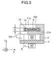
- Fig. 2 is a diagram schematically showing a linear motor according to another embodiment of the invention. A sectional view of this linear motor is shown in Fig. 3.
- the first member includes an alternate arrangement of a plurality of the first opposed portions and the second opposed portions shown in Fig. 1, and the parts thereof other than those holding the second member 6 are formed as a unit.
- Numeral 1 designates a magnetic pole, numeral 11a an upper magnetic pole tooth of the magnetic pole 1, numeral 12b a lower magnetic pole tooth of the magnetic pole 1, numeral 2 a magnetic pole, numeral 21 a lower magnetic pole tooth of the magnetic pole 2, numeral 22a an upper magnetic pole tooth of the magnetic pole 2, numeral 3 a first member, numeral 4 a winding, numeral 5 an iron core, numeral 6 a second member, numeral 8 a gap between the upper magnetic pole tooth 11a of the magnetic pole 1 and the lower magnetic pole tooth 21b of the magnetic pole 2 (the lower magnetic pole tooth 12b of the magnetic pole 1 and the upper magnetic pole tooth 22a of the magnetic pole 2), and character Ps the pole pitch between the centers of the magnetic pole teeth of the first opposed portion and the second opposed portion.
- the magnetic poles 1, 2 are arranged on the two sides of the iron core 5 on the bottom portion of the first member 3, and the winding 4 is wound longitudinally on a linear elongate iron core having a channel-shaped section open upside thereby to hold the two magnetic poles 1, 2.
- the magnetic pole 1 has on the upper surface thereof the upper magnetic pole tooth 11a, the lower magnetic pole tooth 12b and so forth protruded toward the magnetic pole 2, while the magnetic pole 2 has on the upper surface thereof the lower magnetic pole tooth 21b, the upper magnetic pole tooth 22a and so forth protruded toward the magnetic pole 1.
- the (2n-1)th (n: 1, 2, 3,...) protruded magnetic pole tooth of the magnetic pole 1 is arranged upside and the (2n)th (n: 1, 2, 3,...) magnetic pole tooth is arranged downside so as to form two stages of the magnetic pole teeth.
- the (2n-1)th protruded magnetic pole tooth of the magnetic pole 2 is arranged downside and the (2n)th (n: 1, 2, 3,...) magnetic pole tooth thereof is arranged upside so as to form two similar stages of the magnetic pole teeth.
- the upper magnetic pole teeth of the magnetic pole 1 and the magnetic pole 2 as a whole are defined as an upper magnetic pole surface, and the lower magnetic pole teeth as a whole defined as a lower magnetic pole surface. Then, the magnetic pole teeth of the magnetic pole 1 and the magnetic pole 2 in opposed relation to each other form two alternate upper and lower magnetic pole surfaces.
- the first upper magnetic pole tooth 11a and the lower magnetic pole tooth 21b are defined as the first opposed portion, and the second lower magnetic pole tooth 12b and the upper magnetic pole tooth 22a as the second opposed portion.
- a first member is configured so that the (2n-1)th magnetic pole tooth is the first opposed portion and the (2n)th magnetic pole tooth is the second opposed portion.
- a predetermined gap 8 is formed between the upper magnetic pole tooth and the lower magnetic pole tooth of each opposed portion, and a second member is inserted through the gap 8. Then, the second member is held by the first opposed portion thereby to form a structure in which the second member is held by the second opposed portion.
- a support mechanism (first member side) 14 supports the second member 6 relatively moving on the first member 3 side
- a support mechanism (second member side) 15 supports the second member 6 relatively moving on the second member 6 side.
- the second member 6, supported on the support mechanisms 14, 15, relatively moves through the gap 8 in such a manner as to pass through a tunnel.
- the attraction force acting between the second member 6 and the upper magnetic pole tooth is substantially the same in magnitude as the attraction force acting between the second member 6 and the lower magnetic pole tooth, and the two attraction forces work in opposite directions.
- the attraction force is reduced as a whole.
- the attraction force between the second member 6 and the magnetic pole tooth of the first member 3 can be reduced for a smaller burden on the support mechanisms 14, 15.
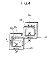
- Fig. 4 is a diagram schematically showing the flow of the magnetic fluxes in the linear motor according to this embodiment.
- the upper and lower magnetic pole teeth mounted on the magnetic pole 2 assume a S pole in the case where the upper and lower magnetic pole teeth mounted on the magnetic pole 1 are a N pole.
- the magnetic fluxes flow from the upper magnetic pole tooth 11a of the magnetic pole 1 to the lower magnetic pole tooth 21b of the magnetic pole 2.
- the magnetic fluxes flow from the lower magnetic pole tooth 12b of the magnetic pole 1 to the upper magnetic pole tooth 22a of the magnetic pole 2.
- the magnetic fluxes flow in opposite directions for each pole pitch in the gap 8 between the upper magnetic pole surface and the lower magnetic pole surface.
- the magnetic path of the magnetic circuit of effective magnetic fluxes is shortened, the magnetic reactance decreases, the effective magnetic fluxes increase, and the leakage magnetic fluxes are reduced.
- Figs. 5A to 5D are block diagrams showing the control operation using a linear motor according to this embodiment.
- Fig. 5A is a block diagram showing a closed loop control system including a linear motor (indicated as "Motor” in the drawing) including the first member and the second member described above, a sensor (not shown) for detecting the relative displacement (indicated as “Displacement” in the drawing) of the first member and the second member and the magnetic pole (indicated as “Magnetic pole position” in the drawing) and a control unit (indicated as “Controller” in the drawing) for feeding back the signals (indicated as “Signals” in the drawing) of the sensor and a power drive unit (indicated as “Driver” in the drawing) for driving the linear motor with power from an external power source or an internal power source (indicated as "Power source” in the drawing).
- the control unit is supplied with instructions (indicated as "Instructions” in the drawing) such as a speed instruction from other sources
- Fig. 5B is another block diagram showing an open loop control system including a linear motor (indicated as “Motor” in the drawing) including the first member and the second member, a control unit (indicated as “Controller” in the drawing) and a power drive unit (indicated as “Driver” in the drawing).
- a linear motor indicated as “Motor” in the drawing
- Control unit indicated as “Controller” in the drawing
- Driver power drive unit
- Fig. 5C is still another block diagram showing a magnetic pole sensorless control system including a linear motor (indicated as “Motor” in the drawing) having the first member and the second member, a voltage sensor, a control unit (indicated as “Controller” in the drawing) and a power drive unit (indicated as “Driver” in the drawing).
- the induced voltage (indicated as “Eo” in the drawing) generated by the linear motor is read into the control unit by use of the voltage sensor.
- the magnetic pole position is estimated from the magnitude of the induced voltage, and a signal for driving the linear motor is output to the power drive unit (indicated as "Driver” in the drawing).
- the linear motor can be driven stably without mounting a magnetic pole position sensor on the linear motor unit.
- Fig. 5D is still another block diagram showing a configuration of a magnetic pole sensorless control system including a linear motor (indicated as "Motor” in the drawing) having the first member and the second member, a current sensor, a control unit (indicated as “Controller” in the drawing) and a power drive unit (indicated as “Driver” in the drawing).
- the current (indicated as “I” in the drawing) flowing in the linear motor is read into the control unit by use of the current sensor.
- the induced voltage of the linear motor is calculated and the magnetic pole position is estimated from the detection current value and the voltage applied to the linear motor.
- the linear motor can be driven stably without mounting a magnetic pole position sensor on the linear motor unit.
- FIGs. 6 and 7 A schematic diagram and an exploded view of a linear motor configured of a steel laminate according to this embodiment are shown in Figs. 6 and 7, respectively.
- the first member is formed of a steel laminate as shown in Fig. 4, and has such a structure that a plurality of the first opposed portions and the second opposed portions are arranged alternately.
- Fig. 7 shows a method of manufacturing a linear motor comprising the first member and the second member, in which the iron core portion with the winding of the first member arranged therein and the magnetic pole portion having the opposed portion holding the second member are assembled from steel laminates in segmentation.
- Figs. 7A and 7B schematically show the case in which the winding of the first member is accommodated and arranged at the ends (Fig. 7A) and the case in which it is arranged at the center (Fig. 7B) of the iron core portion open in the shape of a channel.
- a single excitation winding is used for the first member so that the direction of the current flow is switched alternately by the drive circuit (called the unifilar winding).
- two windings for the first member are wound in opposite directions on the same iron core and a current is supplied to the alternate windings in the same direction from the drive circuit (called the bifilar winding).
- Either the unifilar winding or the bifilar winding can be used for any of the methods of arranging the winding 4 shown in Figs. 7A and 7B.
- Fig. 7C shows a magnetic pole unit having an opposed portion holding the second member.
- a linear motor of a simple structure can be manufactured by assembling by segmentation the iron core portion with the winding of the first member arranged thereon and the magnetic pole portion having the opposed portion holding the second member.
- An assembly method is available for fastening with bolts or rivets (not shown), welding or integration using resin.
- winding process with a segmented core will be explained.
- winding 4 is arranged on the integrated assembly including the iron core portion with the winding of the first member arranged thereon and the core of the magnetic pole portion having the opposed portion holding the second member, windings as many as turns thereof are required to be passed along the steel laminate thickness of the iron core portion.
- the winding 4 can be easily inserted as shown in Figs. 7A to 7C, however, by manufacturing by segmentation the iron core portion with the winding of the first member arranged thereon and the core of the magnetic pole portion having the opposed portion holding the second member.
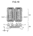
- Fig. 19 is a plan view (a) and a sectional view (b) of the winding 4 of Fig. 7A accommodated in channel-shaped steel laminates (1, 2, 3, 5). A predetermined interval is maintained between the magnetic poles formed of the steel laminates (1, 2, 3, 5) using a duct or resin (not shown).
- the two windings 4 are arranged as a coil 1 and a coil 2 to surround the pole portions (1, 2) of the steel laminates.
- Fig. 20 is a sectional view showing a combination of Figs. 7A and 7C.
- the second member 6, like in Fig. 3 is supported by the support mechanisms 14, 15 and adapted to move relatively through the gap 8 in such a manner as to pass through a tunnel.
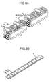
- Fig. 8A shows a linear motor comprising the two first members of Fig. 2 arranged in series.
- the first member A and the first member B are arranged in series so that the pitch between the magnetic pole teeth of the first member A and the adjacent magnetic pole teeth of the first member B is given as (k ⁇ P + P/M) ⁇ k: 0, 1, 2,..., and M: 2, 3, 4,... ⁇ , where P is the pole pitch (selected as the armature magnetic pole pitch Ps or as the second member pole pitch Pm), and M is the number of phases of the motor.
- P the pole pitch (selected as the armature magnetic pole pitch Ps or as the second member pole pitch Pm)
- the second member 6 has a plurality of permanent magnets 7 arranged with adjacent magnetic poles in different polarities and magnetized in the Z direction as shown in Fig. 3.
- the winding 4 of the first member A and the second member B in such a manner as to generate a moving magnetic field alternately, magnetic fluxes flow in the gap 8 between the upper magnetic pole surface and the lower magnetic pole surface in opposite directions for each pole pitch.
- the propulsive force is generated by the pitch P/2 essential for movement and the second member 6 moves relatively.
- Fig. 9A shows a linear motor comprising two first members of Fig. 2 arranged in parallel.
- the second member 6a and the second member 6b are integrated by being displaced by a pitch of P/2.
- the second member 6a and the second member 6b may be aligned while the first member A and the second member B may be displaced by the pitch P/2.
- the magnetic pole pitch Ps of the first member and the magnetic pole pitch Pm of the second member may have the same or different values. In the case where the magnetic pole pitch Ps of the first member and the magnetic pole pitch Pm of the second member have different values, the pulsation of the propulsive force acting between the permanent magnet 7 and the magnetic pole teeth can be reduced.
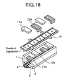
- Fig. 18 is an exploded view of a part of the linear motor shown in Fig. 8A.
- the magnetic poles 1, 2 and the magnetic pole teeth 11a, 12b, 21b, 22a are produced by segmentation, and the magnetic pole 1 is combined with the magnetic pole teeth 11a, 12b and the magnetic pole 2 with the magnetic pole teeth 21b, 22a thereby to produce the first member.
- the magnetic pole on one side can be integrated with the upper and lower magnetic pole teeth of the same magnetic pole by pressing. Further, the magnetic poles on the two sides can be combined with the magnetic pole teeth thereof by pressing.
- the support mechanism 14 is fixed on the first member to support the second member horizontally and vertically.
- the arrow in the drawing indicates the direction of magnetization (indicated as "Direction of magnetization" in the drawing).
- Figs. 10A to 10B are schematic diagrams showing the first members arranged in series according to another embodiment of the invention.
- Figs. 10A and 10B four first members are arranged, of which each two first members are assumed to represent one phase, and the pole pitch is given as P.
- FIG. 10A shows an arrangement of phase A, phase B, phase A and phase B of the first members in that order
- Fig. 10B shows an arrangement of phase A, phase A, phase B and phase B of the first members in that order.
- a linear motor having a large propulsive force can be obtained by arranging a plurality (multiplicity) of first members in one phase.
- a similar effect can be obtained by arranging a plurality of first members in series. This is also the case in which a plurality of first members are arranged in parallel and a plurality of second members are integrated with each other.
- Fig. 11 shows a tabular second member according to another embodiment of the invention.
- Fig. 12 shows an example in which the second member is cylindrical instead of tabular unlike in Fig. 11.
- the provision of protruded magnetic pole teeth 13 on the two sides of a tabular ferromagnetic material changes the magnetic reactance with the magnetic pole of the opposed portion of the first member in the direction of progress.
- the magnetic reactance between the protruded magnetic pole teeth 13 and the magnetic pole of the opposed portion of the first member is smaller than the magnetic reactance between the tabular portion 16 of the ferromagnetic material and the magnetic pole of the opposed portion of the first member.
- a movable second member can be obtained by utilizing this change of magnetic reactance. It is also possible to obtain a composite second member by providing the protruded magnetic pole teeth 13 of a ferromagnetic material and arranging a permanent magnet on the tabular portion 16.
- the tabular portion 16 can be formed as a non-magnetic material in combination with the protruded magnetic pole teeth 13 of a ferromagnetic material.
- ferromagnetic material 36 and the non-magnetic material 37 are combined on a shaft 35.
- a permanent magnet may be used.
- the second member 6 may be formed as an endless belt or chain (not shown) with a ferromagnetic material embedded therein. Also, a permanent magnetic may be used alternatively.
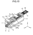
- Fig. 13 schematically shows a linear motor according to another embodiment of the invention.
- an explanation will be given of an embodiment of the invention using a winding 57 in place of the permanent magnet 7 as a second member.
- Fig. 13 represents an example in which the winding 57 is used in place of the permanent magnet 7 as a second member.
- the relative movement is made possible by a configuration in which the winding 4 of the first member has the function of a field winding due to DC excitation and the winding 57 of the second member has the function of an armature winding for generating a moving magnetic field of a plurality of phases with a lead wire (not shown).
- the detent force a force (called the detent force) is generated between the permanent magnet 7 of the second member and the magnetic pole of the opposed portion of the first member even when the winding 4 of the first member is not excited.
- the use of the winding 57 in place of the permanent magnet 7 as the second member has the effect of eliminating the detent force which otherwise might act between the first member and the second member during no excitation.
- the winding 57 of the second member can be provided either as a winding type with a core making up the winding 57 with the ferromagnetic material 58 or as a coreless winding type (also called the hollow coil type) making up the winding 57 without the ferromagnetic material 58.
- Fig. 14 shows an example in which the winding of the second member shown in Fig. 13 is arranged for a two-phase linear motor.
- Fig. 14A is a schematic diagram showing an arrangement of the winding 57 including phase A (indicated so in the drawing) and phase B (indicated so in the drawing) for the second member 6.
- Fig. 14B is a sectional view showing the second member of Fig. 14A held by the upper and lower magnetic pole teeth having the opposed portion of the first member.
- the winding 4 of the first member shown in Fig. 13 has the function of a field winding due to DC excitation, and the winding 57 is given a two-phase moving magnetic field by a power driver (not shown), so that the first and second members move relatively to each other.
- the upper magnetic pole teeth are indicated as "the upper magnetic poles" and the lower magnetic pole teeth are indicated as "the lower magnetic poles" in the drawing.
- Figs. 15A and 15B show an example in which the winding of the second member 6 shown in Fig. 13 is arranged as a three-phase linear motor.
- Figs. 16A and 16B show another embodiment in which the number of bundles of the windings of the second member 6 shown in Figs. 15A and 15B is doubled.
- Both Figs. 15A, 15B and 16A, 16B show the case in which the winding arrangement of the second member makes up a three-phase motor. Nevertheless, the basic operating principle of these cases is the same as that described with reference to Fig. 13, and the winding 57 is supplied with a three-phase moving magnetic field by a power driver (not shown) thereby to cause relative movements of the first and second members.
- a power driver not shown
- the three-phase winding is indicated as “phase U” or “U”, “phase V” or “V” and “phase W” or “W”, respectively.
- the upper magnetic pole teeth are indicated as “the upper magnetic poles”
- the lower magnetic pole teeth are indicated as “the lower magnetic poles”.
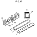
- Fig. 17 shows a method of manufacturing a linear motor according to an embodiment of the invention.
- the iron core wound with the winding 4, the magnetic poles on the two sides, the upper magnetic pole teeth 11a and the lower magnetic pole teeth 21b of the opposed portion are produced by segmentation, and an integrated iron core 101 of the first opposed portion is produced with a steel laminate at the time of assemblage.
- the iron core 102 of the second opposed portion is constituted.
- a support mechanism 32 and a duct 33 are interposed between the iron core 101 of the first opposed portion and the iron core 102 of the second opposed portion.
- a first member is formed in such a structure that the (2n-1)th iron core represents the first opposed portion and the (2n)th iron core represents the second opposed portion.
- the iron core 101 of the first opposed portion and the iron core 102 of the second opposed portion are each segmented into left and right halves as units and the winding 4 is held by right and left sides for assemblage.
- the embodiments of the present invention are applicable to a multi-phase linear motor such as a four- or five-phase linear motor as well as the two- and three-phase linear motors described above.
- the first member and the second member of the embodiments may be such that an AC current is supplied to the winding 4 of the first member or the winding 57 of the second member and thus a linear actuator of oscillation type can be realized with the second member relatively reciprocating.
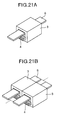
- Figs. 21A and 21B show the first members arranged in parallel according to an embodiment of the invention.
- Fig. 21A schematically shows a basic structure including a single mold of the first member 3 and the second member 6.
- Fig. 21B shows a parallel arrangement of two basic structures.
- a plurality of the first members 3 and a plurality of the second members 6 are each integrally coupled with each other, so that a plurality of the first members 3 are fixed while a plurality of the second members 6 are movable.
- the second members 6 may be fixed while the first members 3 may be movable.
- Figs. 22A and 22B show winding arrangements according to another embodiment.
- Figs. 22A and 22B show winding arrangements according to another embodiment.
- Figs. 22A and 22B show winding arrangements according to another embodiment.
- Figs. 22A and 22B show winding arrangements according to another embodiment.
- Figs. 22A and 22B show winding arrangements according to another embodiment.
- Figs. 22A and 22B show winding arrangements according to another embodiment.
- Fig. 22A and 22B shows a case in which the winding 4 is arranged in a single bundle in parallel to the second member 6 on the bottom of the iron core portion 3
- Fig. 22B a case in which the winding 4 is arranged in two bundles on the two sides of the iron core portion 3.
- the winding is not expanded laterally as viewed from the front and therefore the width can be reduced.
- Fig. 22B on the other hand, the winding is not expanded vertically as viewed from the front, and therefore the vertical thickness can be reduced
- Figs. 23A and 23B show front views of a parallel (horizontal) arrangement of the iron cores providing the first members 3.
- Fig. 23A shows an arrangement of the winding 4 extending over two adjacent iron cores
- Fig. 23B shows a case in which in addition to the winding arrangement of Fig. 23A, the winding 4 is additionally arranged on each of the two outer sides of each iron core portion.
- the windings 4 can be arranged freely even in the case where the iron cores making up the first members 3 are arranged in parallel.
- Figs. 24A and 24B are front views showing another example of a parallel (vertical) arrangement of the iron core portions making up the first member.
- Fig. 24A shows a case in which the back sides (the sides far from the mover making up the second members 6) of the iron core portions (first members 3) having the winding 4 wound thereon are arranged in vertically opposed relation to each other with the windings 4 arranged over the two iron core portions.
- Fig. 24B shows a similar case in which the back sides of the iron core portions (first members 3) are arranged in vertically opposed relation to each other with a plurality of sets (four sets are shown) of windings 4 are arranged vertical and horizontal positions. As a result, the windings 4 can be arranged freely even in the case where the iron cores making up the first members 3 are arranged in parallel.
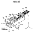
- Fig. 25 shows the first member 3 according to another embodiment. As shown in Fig. 25, this embodiment is such that the electromagnet including the winding 4 and the iron core 5 shown in Fig. 13 is replaced with a permanent magnet 55 having the direction of magnetization indicated by arrow. In this case, the winding 4 and hence the space for the winding 4 is eliminated for an improved space availability factor.
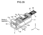
- Fig. 26 shows the first member according to still another embodiment.
- the permanent magnet 55 according to the embodiment shown in Fig. 25 is arranged on the two sides of the iron core portion 3.
- This embodiment has a plurality of (two) permanent magnets 55 having the directions of magnetization indicated by arrows in Fig. 26.
- the winding 4 is not required also in this case, and therefore the saving of the space for the winding improves the space availability factor.
- the permanent magnet shown in Figs. 25 and 26, even when configured integrally, has the same effect from the viewpoint of the basic operating principle.
- the permanent magnet may be assembled by producing in segmentations conforming to the pitch of the magnetic pole teeth.
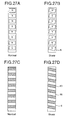
- Figs. 27A and 27B show an embodiment in which the magnetic poles of the second member 6 are skewed (arranged diagonally).
- Fig. 27B shows a second member 6 using permanent magnets with skewed magnetic poles
- Fig. 27A shows a (normal) second member 6 not skewed
- Fig. 27D shows the ferromagnetic material 13 of Fig. 11 with the magnetic poles thereof skewed (diagonally arranged)
- Fig. 27C shows a (normal) ferromagnetic material 13 not skewed.
- the same effect can be obtained by skewing the composite second member 6 made of a permanent magnet and a ferromagnetic material. The skewing reduces the detent force for a smaller propulsion ripple.
- the magnetic path of the magnetic circuit of effective magnetic fluxes is shortened and the leakage magnetic fluxes of the magnetic pole teeth can be reduced.
- the attraction force acting between the second member 6 and the upper magnetic pole teeth has the same magnitude as the attraction force exerted between the second member 6 and the lower magnetic pole teeth.
- the attraction forces are exerted in opposite directions, thereby reducing the whole attraction force.
- the attraction force between the second member 6 and the magnetic pole teeth of the first member 3 can be reduced for a smaller burden on the support mechanisms 14, 15.
- the linear motor according to the present invention can be easily and efficiently manufactured.
- a linear motor comprising a first member and a second member, wherein the first member includes at least a magnetic pole of a first magnetic polarity having a first opposed portion and a magnetic pole of a second magnetic polarity having a second opposed portion, the second member is held by the first opposed portion and also held by the second opposed portion for relative movement.
- the first member is made of an iron core and a winding
- the second member is made of a permanent magnet, a magnetic material, a single type of winding or a combination of a plurality of types of materials.
- a linear motor and a method of manufacturing the linear motor in which the leakage of the magnetic fluxes passing through the gap between the magnetic pole teeth is reduced thereby to reduce the magnetic attraction force between the armature and the mover.
Landscapes
- Engineering & Computer Science (AREA)
- Physics & Mathematics (AREA)
- Chemical & Material Sciences (AREA)
- Combustion & Propulsion (AREA)
- Electromagnetism (AREA)
- Power Engineering (AREA)
- Linear Motors (AREA)
- Iron Core Of Rotating Electric Machines (AREA)
- Control Of Linear Motors (AREA)
- Manufacture Of Motors, Generators (AREA)
Applications Claiming Priority (2)
| Application Number | Priority Date | Filing Date | Title |
|---|---|---|---|
| JP2000316844A JP3945142B2 (ja) | 2000-10-12 | 2000-10-12 | リニアモータ及びその制御方法 |
| JP2000316844 | 2000-10-12 |
Publications (3)
| Publication Number | Publication Date |
|---|---|
| EP1198055A2 true EP1198055A2 (fr) | 2002-04-17 |
| EP1198055A3 EP1198055A3 (fr) | 2002-07-31 |
| EP1198055B1 EP1198055B1 (fr) | 2017-08-23 |
Family
ID=18795733
Family Applications (1)
| Application Number | Title | Priority Date | Filing Date |
|---|---|---|---|
| EP01104715.6A Expired - Lifetime EP1198055B1 (fr) | 2000-10-12 | 2001-02-26 | Moteur linéaire, ses systèmes de commande et d'entrainement et son procédé de fabrication |
Country Status (4)
| Country | Link |
|---|---|
| US (1) | US6614137B2 (fr) |
| EP (1) | EP1198055B1 (fr) |
| JP (1) | JP3945142B2 (fr) |
| KR (1) | KR100743117B1 (fr) |
Cited By (3)
| Publication number | Priority date | Publication date | Assignee | Title |
|---|---|---|---|---|
| CN102214983A (zh) * | 2010-04-07 | 2011-10-12 | 株式会社日立制作所 | 直线电机 |
| CN103141017A (zh) * | 2010-08-23 | 2013-06-05 | 科韦里有限公司 | 线性马达 |
| CN103312116A (zh) * | 2013-05-13 | 2013-09-18 | 深圳大学 | 一种段式平面开关磁阻电机 |
Families Citing this family (25)
| Publication number | Priority date | Publication date | Assignee | Title |
|---|---|---|---|---|
| JP3395155B2 (ja) | 1999-05-07 | 2003-04-07 | 株式会社日立製作所 | リニアモータ及びその製造方法 |
| JP3945148B2 (ja) * | 2000-11-02 | 2007-07-18 | 株式会社日立製作所 | Xyテーブル及びxyzテーブル |
| SE524861C2 (sv) * | 2002-08-14 | 2004-10-12 | Abb Ab | En elektrisk maskin samt användning därav |
| US6883333B2 (en) * | 2002-11-12 | 2005-04-26 | The Penn State Research Foundation | Sensorless control of a harmonically driven electrodynamic machine for a thermoacoustic device or variable load |
| JP3855914B2 (ja) * | 2002-11-12 | 2006-12-13 | 株式会社日立製作所 | 直線駆動装置 |
| JP3821101B2 (ja) | 2003-02-04 | 2006-09-13 | 株式会社日立製作所 | 直線駆動装置、その制御方法及びxyテーブル |
| KR100518780B1 (ko) * | 2003-07-16 | 2005-10-06 | 학교법인 한양학원 | 선형 엑츄에이터를 위한 가동자 |
| JP4089597B2 (ja) * | 2003-11-18 | 2008-05-28 | 株式会社日立製作所 | リニアモータ及びxyステージ |
| JP2006115665A (ja) * | 2004-10-18 | 2006-04-27 | Toyo Mach & Metal Co Ltd | 直線駆動装置 |
| DE102006012736A1 (de) * | 2006-03-17 | 2007-09-20 | Siemens Ag | Elektrische Maschine |
| KR101140925B1 (ko) * | 2006-05-08 | 2012-05-03 | 신꼬오덴끼가부시끼가이샤 | 자동차 차체의 진동을 저감하는 자동차용 제진장치 |
| JP2009189092A (ja) * | 2008-02-04 | 2009-08-20 | Hoya Corp | 直線型揺動アクチュエータ |
| KR101657276B1 (ko) | 2008-11-18 | 2016-09-13 | 히다찌긴조꾸가부시끼가이사 | 가동자, 전기자 및 리니어모터 |
| KR101050552B1 (ko) * | 2009-06-04 | 2011-07-21 | 연세대학교 산학협력단 | 비접촉 강자성체 추진 장치 및 그 제어방법 |
| US20130082545A1 (en) * | 2010-06-08 | 2013-04-04 | Kengo Goto | Linear Motor |
| US9300186B2 (en) * | 2011-08-12 | 2016-03-29 | Choo-Peng Oh | Electrically powered reciprocating motor |
| US10044251B2 (en) * | 2013-03-22 | 2018-08-07 | Hitachi Metals, Ltd. | Linear motor |
| JP6028013B2 (ja) | 2014-12-25 | 2016-11-16 | Thk株式会社 | リニアモータ |
| JP6596767B2 (ja) * | 2015-07-14 | 2019-10-30 | 日立金属株式会社 | リニアモータ用界磁部及びリニアモータ |
| US10811950B2 (en) * | 2015-08-07 | 2020-10-20 | Hitachi, Ltd. | Linear motor and device provided with linear motor |
| FR3093874B1 (fr) * | 2019-03-15 | 2021-04-16 | Commissariat Energie Atomique | dispositif électromagnétique |
| JP7159451B2 (ja) * | 2019-03-28 | 2022-10-24 | 富士フイルム株式会社 | 電磁アクチュエータ |
| CN112271902B (zh) * | 2020-10-22 | 2022-07-05 | 长航集团武汉电机有限公司 | 一种同性极混合励磁直线同步电机 |
| US12142984B2 (en) * | 2021-07-15 | 2024-11-12 | Etalim Inc. | Transducer apparatus having magnetic flux generators with pole pieces, reciprocators and closing pieces for channeling magnetic flux |
| KR20250007568A (ko) * | 2022-05-18 | 2025-01-14 | 주식회사 코베리 | 선형 전동기 |
Citations (1)
| Publication number | Priority date | Publication date | Assignee | Title |
|---|---|---|---|---|
| JPS63310361A (ja) | 1987-06-12 | 1988-12-19 | Tokyo Electric Co Ltd | リニアパルスモ−タ |
Family Cites Families (17)
| Publication number | Priority date | Publication date | Assignee | Title |
|---|---|---|---|---|
| FR1592065A (fr) | 1967-01-25 | 1970-05-11 | ||
| US4254350A (en) * | 1979-07-12 | 1981-03-03 | Miroshnichenko Vitaly T | Asynchronous line-fed motor |
| JPS62193553A (ja) | 1986-02-18 | 1987-08-25 | Yaskawa Electric Mfg Co Ltd | 永久磁石形リニア電磁アクチユエ−タ |
| JPS6395849A (ja) | 1986-10-07 | 1988-04-26 | Yaskawa Electric Mfg Co Ltd | リニアパルスモ−タ |
| JPS63107452A (ja) | 1986-10-21 | 1988-05-12 | Omron Tateisi Electronics Co | 平板状リニアパルスモ−タ |
| US4912746A (en) * | 1987-08-15 | 1990-03-27 | Shinko Denki Kabushiki Kaisha | Linear DC brushless motor |
| US4945268A (en) * | 1987-12-26 | 1990-07-31 | Hitachi, Ltd. | Permanent magnet type linear pulse motor |
| US5166749A (en) * | 1991-05-22 | 1992-11-24 | Bio-Rad Laboratories | Step scanning technique for interferometer |
| FR2697695B1 (fr) | 1992-11-04 | 1995-01-13 | Cachan Ecole Normale Superieur | Dispositif de conversion électromécanique produisant un mouvement en particulier linéaire. |
| US5426353A (en) * | 1993-03-30 | 1995-06-20 | Honeywell Inc. | Synchronous motor system employing a non-synchronous motor for enhanced torque output |
| US5416397A (en) * | 1993-10-04 | 1995-05-16 | Ford Motor Company | Linear motor control system and method of use |
| DE4413601A1 (de) | 1994-04-20 | 1996-05-23 | Pasim Mikrosystemtechnik Gmbh | Modulbaustein |
| JPH0880083A (ja) * | 1994-09-06 | 1996-03-22 | Hitachi Ltd | ブラシレス直流モータの駆動方法 |
| US5619112A (en) * | 1995-02-09 | 1997-04-08 | Woodward Governor Company | Bi-directional electric torque motor and driver |
| JP3791082B2 (ja) | 1996-12-04 | 2006-06-28 | 株式会社安川電機 | リニアモータ |
| US6369479B1 (en) * | 1998-01-27 | 2002-04-09 | Genesis Co., Ltd. | Hybrid-type magnet and stepping motor including same |
| JP3395155B2 (ja) | 1999-05-07 | 2003-04-07 | 株式会社日立製作所 | リニアモータ及びその製造方法 |
-
2000
- 2000-10-12 JP JP2000316844A patent/JP3945142B2/ja not_active Expired - Lifetime
-
2001
- 2001-02-26 US US09/791,720 patent/US6614137B2/en not_active Expired - Lifetime
- 2001-02-26 EP EP01104715.6A patent/EP1198055B1/fr not_active Expired - Lifetime
- 2001-02-27 KR KR1020010009854A patent/KR100743117B1/ko not_active Expired - Lifetime
Patent Citations (1)
| Publication number | Priority date | Publication date | Assignee | Title |
|---|---|---|---|---|
| JPS63310361A (ja) | 1987-06-12 | 1988-12-19 | Tokyo Electric Co Ltd | リニアパルスモ−タ |
Cited By (5)
| Publication number | Priority date | Publication date | Assignee | Title |
|---|---|---|---|---|
| CN102214983A (zh) * | 2010-04-07 | 2011-10-12 | 株式会社日立制作所 | 直线电机 |
| CN102214983B (zh) * | 2010-04-07 | 2014-02-12 | 株式会社日立制作所 | 直线电机 |
| CN103141017A (zh) * | 2010-08-23 | 2013-06-05 | 科韦里有限公司 | 线性马达 |
| CN103312116A (zh) * | 2013-05-13 | 2013-09-18 | 深圳大学 | 一种段式平面开关磁阻电机 |
| CN103312116B (zh) * | 2013-05-13 | 2016-04-27 | 深圳大学 | 一种段式平面开关磁阻电机 |
Also Published As
| Publication number | Publication date |
|---|---|
| JP3945142B2 (ja) | 2007-07-18 |
| KR20020029293A (ko) | 2002-04-18 |
| US6614137B2 (en) | 2003-09-02 |
| JP2002125360A (ja) | 2002-04-26 |
| KR100743117B1 (ko) | 2007-07-27 |
| EP1198055A3 (fr) | 2002-07-31 |
| US20020043879A1 (en) | 2002-04-18 |
| EP1198055B1 (fr) | 2017-08-23 |
Similar Documents
| Publication | Publication Date | Title |
|---|---|---|
| US6614137B2 (en) | Linear motor, driving and control system thereof and manufacturing method thereof | |
| JP3395155B2 (ja) | リニアモータ及びその製造方法 | |
| JP3945148B2 (ja) | Xyテーブル及びxyzテーブル | |
| US6522035B1 (en) | Forcer and associated three phase linear motor system | |
| WO2002036917A1 (fr) | Systeme de porte | |
| US6753627B2 (en) | Linear motor | |
| JP2002138957A (ja) | 流体搬送装置 | |
| JP4061834B2 (ja) | リニアモータ | |
| US6570274B2 (en) | Electric motor | |
| JP3430770B2 (ja) | ドア開閉用リニアモータ | |
| JP3175554B2 (ja) | 直流リニアモータ | |
| US7250696B2 (en) | Linear motor and X-Y stage | |
| JP2003134791A (ja) | 永久磁石形同期リニアモータ | |
| JP3906443B2 (ja) | リニアモータ | |
| JP2002034230A (ja) | リニアモータの電機子 | |
| JP2004336842A (ja) | リニアモータ | |
| JPH08140330A (ja) | 可動磁石形リニアモータ | |
| JP4458078B2 (ja) | リニアモータ及びその制御方法 | |
| JP2005057822A (ja) | リニアモータ | |
| JP2005176506A (ja) | リニアモータ | |
| JPH07245932A (ja) | リニアモータ | |
| JPS63242160A (ja) | リニア同期電動機 | |
| JPH10225095A (ja) | 直流リニアモータ | |
| JP2004140954A (ja) | リニアモータ | |
| JP2016082653A (ja) | リニアモータおよびリニアモータ装置 |
Legal Events
| Date | Code | Title | Description |
|---|---|---|---|
| PUAI | Public reference made under article 153(3) epc to a published international application that has entered the european phase |
Free format text: ORIGINAL CODE: 0009012 |
|
| AK | Designated contracting states |
Kind code of ref document: A2 Designated state(s): AT BE CH CY DE DK ES FI FR GB GR IE IT LI LU MC NL PT SE TR |
|
| AX | Request for extension of the european patent |
Free format text: AL;LT;LV;MK;RO;SI |
|
| PUAL | Search report despatched |
Free format text: ORIGINAL CODE: 0009013 |
|
| AK | Designated contracting states |
Kind code of ref document: A3 Designated state(s): AT BE CH CY DE DK ES FI FR GB GR IE IT LI LU MC NL PT SE TR |
|
| AX | Request for extension of the european patent |
Free format text: AL;LT;LV;MK;RO;SI |
|
| 17P | Request for examination filed |
Effective date: 20020917 |
|
| AKX | Designation fees paid |
Designated state(s): DE FR GB |
|
| 17Q | First examination report despatched |
Effective date: 20081105 |
|
| STAA | Information on the status of an ep patent application or granted ep patent |
Free format text: STATUS: EXAMINATION IS IN PROGRESS |
|
| GRAP | Despatch of communication of intention to grant a patent |
Free format text: ORIGINAL CODE: EPIDOSNIGR1 |
|
| STAA | Information on the status of an ep patent application or granted ep patent |
Free format text: STATUS: GRANT OF PATENT IS INTENDED |
|
| INTG | Intention to grant announced |
Effective date: 20170314 |
|
| RIN1 | Information on inventor provided before grant (corrected) |
Inventor name: MIYAZAKI, TAIZOU, C/OHITACHI,LTD.,INTELL. PROP. GR Inventor name: KIM, HOUNG JOONG, C/OHITACHI,LTD.,INTELL.PROP.GROU Inventor name: MAKI, KOHJI, C/OHITACHI,LTD.,INTELL. PROP. GROUP Inventor name: HANYU, TOMOYUKI, C/OHITACHI,LTD.,INTELL. PROP. GRO Inventor name: INWAJI, YOSHITAKA, C/OHITACHI,LTD.,INTELL. PROP. G |
|
| GRAS | Grant fee paid |
Free format text: ORIGINAL CODE: EPIDOSNIGR3 |
|
| GRAA | (expected) grant |
Free format text: ORIGINAL CODE: 0009210 |
|
| STAA | Information on the status of an ep patent application or granted ep patent |
Free format text: STATUS: THE PATENT HAS BEEN GRANTED |
|
| RIN1 | Information on inventor provided before grant (corrected) |
Inventor name: KIM, HOUNG JOONG, C/OHITACHI,LTD.,INTELL.PROP.GROU Inventor name: HANYU, TOMOYUKI, C/OHITACHI,LTD.,INTELL. PROP. GRO Inventor name: MAKI, KOHJI, C/OHITACHI,LTD.,INTELL. PROP. GROUP Inventor name: IWAJI, YOSHITAKA, C/OHITACHI,LTD.,INTELL. PROP. GR Inventor name: MIYAZAKI, TAIZOU, C/OHITACHI,LTD.,INTELL. PROP. GR |
|
| AK | Designated contracting states |
Kind code of ref document: B1 Designated state(s): DE FR GB |
|
| RAP1 | Party data changed (applicant data changed or rights of an application transferred) |
Owner name: HITACHI, LTD. |
|
| REG | Reference to a national code |
Ref country code: GB Ref legal event code: FG4D |
|
| REG | Reference to a national code |
Ref country code: DE Ref legal event code: R096 Ref document number: 60150569 Country of ref document: DE |
|
| REG | Reference to a national code |
Ref country code: DE Ref legal event code: R097 Ref document number: 60150569 Country of ref document: DE |
|
| PLBE | No opposition filed within time limit |
Free format text: ORIGINAL CODE: 0009261 |
|
| STAA | Information on the status of an ep patent application or granted ep patent |
Free format text: STATUS: NO OPPOSITION FILED WITHIN TIME LIMIT |
|
| 26N | No opposition filed |
Effective date: 20180524 |
|
| GBPC | Gb: european patent ceased through non-payment of renewal fee |
Effective date: 20180226 |
|
| REG | Reference to a national code |
Ref country code: FR Ref legal event code: ST Effective date: 20181031 |
|
| PG25 | Lapsed in a contracting state [announced via postgrant information from national office to epo] |
Ref country code: GB Free format text: LAPSE BECAUSE OF NON-PAYMENT OF DUE FEES Effective date: 20180226 Ref country code: FR Free format text: LAPSE BECAUSE OF NON-PAYMENT OF DUE FEES Effective date: 20180228 |
|
| PGFP | Annual fee paid to national office [announced via postgrant information from national office to epo] |
Ref country code: DE Payment date: 20200211 Year of fee payment: 20 |
|
| REG | Reference to a national code |
Ref country code: DE Ref legal event code: R071 Ref document number: 60150569 Country of ref document: DE |