EP1199207A2 - Soupape de commande pour ventilation de réservoir à carburant - Google Patents
Soupape de commande pour ventilation de réservoir à carburant Download PDFInfo
- Publication number
- EP1199207A2 EP1199207A2 EP01308880A EP01308880A EP1199207A2 EP 1199207 A2 EP1199207 A2 EP 1199207A2 EP 01308880 A EP01308880 A EP 01308880A EP 01308880 A EP01308880 A EP 01308880A EP 1199207 A2 EP1199207 A2 EP 1199207A2
- Authority
- EP
- European Patent Office
- Prior art keywords
- valve
- fuel
- vapor
- orifice
- path
- Prior art date
- Legal status (The legal status is an assumption and is not a legal conclusion. Google has not performed a legal analysis and makes no representation as to the accuracy of the status listed.)
- Withdrawn
Links
Images


Classifications
-
- F—MECHANICAL ENGINEERING; LIGHTING; HEATING; WEAPONS; BLASTING
- F16—ENGINEERING ELEMENTS AND UNITS; GENERAL MEASURES FOR PRODUCING AND MAINTAINING EFFECTIVE FUNCTIONING OF MACHINES OR INSTALLATIONS; THERMAL INSULATION IN GENERAL
- F16K—VALVES; TAPS; COCKS; ACTUATING-FLOATS; DEVICES FOR VENTING OR AERATING
- F16K17/00—Safety valves; Equalising valves, e.g. pressure relief valves
- F16K17/18—Safety valves; Equalising valves, e.g. pressure relief valves opening on surplus pressure on either side
- F16K17/19—Equalising valves predominantly for tanks
-
- B—PERFORMING OPERATIONS; TRANSPORTING
- B60—VEHICLES IN GENERAL
- B60K—ARRANGEMENT OR MOUNTING OF PROPULSION UNITS OR OF TRANSMISSIONS IN VEHICLES; ARRANGEMENT OR MOUNTING OF PLURAL DIVERSE PRIME-MOVERS IN VEHICLES; AUXILIARY DRIVES FOR VEHICLES; INSTRUMENTATION OR DASHBOARDS FOR VEHICLES; ARRANGEMENTS IN CONNECTION WITH COOLING, AIR INTAKE, GAS EXHAUST OR FUEL SUPPLY OF PROPULSION UNITS IN VEHICLES
- B60K15/00—Arrangement in connection with fuel supply of combustion engines or other fuel consuming energy converters, e.g. fuel cells; Mounting or construction of fuel tanks
- B60K15/03—Fuel tanks
- B60K15/035—Fuel tanks characterised by venting means
- B60K15/03504—Fuel tanks characterised by venting means adapted to avoid loss of fuel or fuel vapour, e.g. with vapour recovery systems
-
- F—MECHANICAL ENGINEERING; LIGHTING; HEATING; WEAPONS; BLASTING
- F16—ENGINEERING ELEMENTS AND UNITS; GENERAL MEASURES FOR PRODUCING AND MAINTAINING EFFECTIVE FUNCTIONING OF MACHINES OR INSTALLATIONS; THERMAL INSULATION IN GENERAL
- F16K—VALVES; TAPS; COCKS; ACTUATING-FLOATS; DEVICES FOR VENTING OR AERATING
- F16K15/00—Check valves
- F16K15/14—Check valves with flexible valve members
- F16K15/148—Check valves with flexible valve members the closure elements being fixed in their centre
-
- F—MECHANICAL ENGINEERING; LIGHTING; HEATING; WEAPONS; BLASTING
- F16—ENGINEERING ELEMENTS AND UNITS; GENERAL MEASURES FOR PRODUCING AND MAINTAINING EFFECTIVE FUNCTIONING OF MACHINES OR INSTALLATIONS; THERMAL INSULATION IN GENERAL
- F16K—VALVES; TAPS; COCKS; ACTUATING-FLOATS; DEVICES FOR VENTING OR AERATING
- F16K24/00—Devices, e.g. valves, for venting or aerating enclosures
- F16K24/04—Devices, e.g. valves, for venting or aerating enclosures for venting only
- F16K24/042—Devices, e.g. valves, for venting or aerating enclosures for venting only actuated by a float
- F16K24/044—Devices, e.g. valves, for venting or aerating enclosures for venting only actuated by a float the float being rigidly connected to the valve element, the assembly of float and valve element following a substantially translational movement when actuated, e.g. also for actuating a pilot valve
-
- Y—GENERAL TAGGING OF NEW TECHNOLOGICAL DEVELOPMENTS; GENERAL TAGGING OF CROSS-SECTIONAL TECHNOLOGIES SPANNING OVER SEVERAL SECTIONS OF THE IPC; TECHNICAL SUBJECTS COVERED BY FORMER USPC CROSS-REFERENCE ART COLLECTIONS [XRACs] AND DIGESTS
- Y10—TECHNICAL SUBJECTS COVERED BY FORMER USPC
- Y10T—TECHNICAL SUBJECTS COVERED BY FORMER US CLASSIFICATION
- Y10T137/00—Fluid handling
- Y10T137/2931—Diverse fluid containing pressure systems
- Y10T137/3003—Fluid separating traps or vents
- Y10T137/3084—Discriminating outlet for gas
- Y10T137/309—Fluid sensing valve
- Y10T137/3099—Float responsive
-
- Y—GENERAL TAGGING OF NEW TECHNOLOGICAL DEVELOPMENTS; GENERAL TAGGING OF CROSS-SECTIONAL TECHNOLOGIES SPANNING OVER SEVERAL SECTIONS OF THE IPC; TECHNICAL SUBJECTS COVERED BY FORMER USPC CROSS-REFERENCE ART COLLECTIONS [XRACs] AND DIGESTS
- Y10—TECHNICAL SUBJECTS COVERED BY FORMER USPC
- Y10T—TECHNICAL SUBJECTS COVERED BY FORMER US CLASSIFICATION
- Y10T137/00—Fluid handling
- Y10T137/7722—Line condition change responsive valves
- Y10T137/7771—Bi-directional flow valves
- Y10T137/7779—Axes of ports parallel
Definitions
- the present invention relates to fuel system valves, and particularly to a flow control valve for regulating the discharge of pressurised fuel vapor from a fuel tank.
- the present invention also relates to such valves which are tank-mounted for venting fuel vapor from various regions inside a vehicle fuel tank to a vapor-recovery canister or other destination.
- the present invention also relates to a tank valve which prevents liquid fuel within a tank venting system from entering and contaminating a vapor recovery canister within the system.
- fuel pump nozzles typically include sensors for shutting off the flow of liquid fuel into the fuel tank when the fuel tank is nearly filled
- fuel pump users may manually override the sensors by continuing to pump fuel after the sensors have automatically and temporarily shut the pump nozzle oft:
- a tank venting system is usually provided with a "fill-limit" control system which assists in triggering the nozzle shutoff mechanism when the level of liquid fuel in the fuel tank has risen to a predetermined level. See, for example, the fill-limit control system disclosed in U.S. Pat. No. 4,816,045 to Szlaga et al.
- Vehicle fuel systems are known to include pressure-relief valves mountable on either fuel tanks or filler necks.
- the venting portion of these conventional valve assemblies has included a pressure-relief valve positioned in a vent passageway having a surface exposed to the pressure in the tank and a yieldable control spring urging the pressure-relief valve normally to close the vent passageway.
- the pressure-relief valve In response to a predetermined superatmospheric pressure, the pressure-relief valve is urged in opposition to the control spring to open the vent passageway.
- valves and systems as discussed above include United States Patent Nos 5,687,778 to Harris; 5,666,989 to Roetker; 4,760,858 to Szlaga and 4,742,844 to Szlaga.
- vapor is vented through the valve 10 and conducted through the tank venting system 16 to prevent escape to the ambient environment.
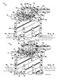
- the tank vent control valve 10 is shown in greater detail in the exploded and sectional views of Figures 2-6, Figure 2 provides an exploded perspective view of the components in the tank vent control valve 10.
- the valve includes the valve housing or housing 34 having an upper portion 36 and a lower portion 38.
- a fuel vapor outlet 40 extends from the upper portion 36.
- a series of components comprising a sealing assembly 42 are contained in the valve housing 34 and retained therein by a retainer cover 44.
- the sealing assembly 42 includes a valve plate 46 with an umbrella valve or control valve 48 carried thereon.
- the umbrella valve 48 as shown and described is a single-piece structure formed of a suitable flexible material such as an elastomeric material.
- a head valve 50 in the form of a displaceable weight is positioned on one side of the valve plate 46 and the umbrella valve 48 and a float valve 69 are positioned on the other side of the plate 46.
- the float valve 69 includes a float body 53 and a biasing member or spring 54.
- the float valve 69 operates generally in accordance with known float and spring principles as applied to tank vent valves.
- the valve plate 46 is generally formed of a rigid material and includes an opening 56 and one or more vacuum vents 58.
- a stem 60 of the umbrella valve 48 extends through the opening 56 of the valve plate 46.
- a web portion or cover portion 62 extends from the stem 60 to controllably cover the vacuum vents 58 as described in greater detail herein. below.
- the cover portion 62 is flexible and selectively displaceable away from and towards the plate 46.
- the umbrella valve 48 and vents 58 generally define a vacuum relief valve 63.
- the head valve weight 50 is positioned and retained in the valve housing 34 to seal against a head valve seat 64 of the umbrella valve 48 under certain conditions.
- the weight 50 axed seat 64 generally define a head valve 65.
- a nipple 66 of the float 52 is sized and dimensioned to seal within a float valve seat 68 on the umbrella valve 48 under certain conditions.
- the float 53, biasing member 54, and seat 68 generally define a float valve 69.
- a vent aperture, passage or orifice 70 is defined by a wall. 71 of the stem 60 extending through the head valve seat 64 and the float valve seat 68.
- at least an outer rim portion 72 of the web 62 is sized and dimensioned to selectively seal against a surface 74 of the valve plate 46.
- the umbrella valve or control valve 48 and the valve plate 46 define a control valve assembly 75.
- the control valve assembly 75 can be formed of two pieces or structures (46, 48) as shown in the view of Figure 2 or may be formed as a single piece structure.
- the single control valve assembly 75 structure can be formed by over-molding elastomeric material forming the umbrella valve 48 on a generally rigid valve plate 46.
- a single piece control valve assembly 75 could be formed of an elastomeric material or a suitably rigid material providing the cover portion 62 having the desired resilient or flexible characteristics as described in the present application.
- the valve plate 46 could be formed as a portion, of the housing at least one vacuum vent 5 8 is formed through the valve plate 46 portion of the housing 34.
- the housing 34 communicates with the fuel tank 14 (Fig. 1) by extension into the internal cavity namely the vapor 22.
- the housing 34 also communicates with the vapor recovery system 15 as a result of the connecting conduit 20 attached to the vapor recovery canister 18.
- the housing 34 defines a path 77 between the fuel tank 14 axed the vapor recovery system 15.
- the path 77 defines a flow path for fuel vapor to pass from the tank 14 for capture by the vapor recovery canister 18.
- the valve plate 4.6 is positioned in the flow path 77 thereby requiring vapor passing from the tank 14 to the vapor recovery system 15 to flow therethrough.
- the valve plate 46 defines a first side 79 of the path 77 communication with the fuel tack 14 and a second side 81 of the path 77 communicating with, the vapor recovery system 15.
- the control valve 48 is generally positioned on the first side 79 of the of the valve plate 46 with the stem 60 extending through the opening 56.
- the float valve 69 and head valve 65 control the flow of the portion of the path 77 passing through the orifice 70.
- the float valve is positioned for controllably covering the first end or float valve seat 68 of the orifice 70.
- Tine bead valve 50 positioned for controllably covering the second end or head valve seat 64 of the orifice.
- the umbrella valve or control valve 48 is positioned over the first side 78 of the valve plate 46 so that the flexible cover portion 62 extends over the vacuum vents 58.
- the cover portion 62 will prevent or block the flow of liquid and vapor through the vent 58.
- the pressure or other force such as sloshing liquid fuel, create a force which positively presses or places the cover portion 62 against the plate 46, the cover portion 62 will prevent the liquid or vapor from passing through the vent 58.
- the force directed toward, the second side 81 of the plate 46 is positive relative to vacuum vent 58 and cover portion 62, the force will disengage the cover portion 62 over the corresponding vacuum vent 58 allowing vapor to flow from the second side 85 of the path 77 to the first side 87 of the path 77.
- the pressure or other forces such as a build-up of liquid fuel or vapor condensate, presses against or is otherwise directed towards the second side 81 to sufficiently to disengage the corresponding cover portion 62 from the valve plate 46, the liquid, vapor or both will be allowed to pass through the vacuum vent 58 towards the fuel tank 14.
- the head valve weight 50 is retained within a head valve cavity 84 of the upper portion 36 of the housing 34.
- the weight 50 is sized and dimensioned relative to the interior dimensions of the cavity 84 to provide a space 86 between an exterior surface 88 of the weight and an interior surface 90 of the cavity 84. This dimensional differential is provided to allow for passage of vapors 80 therearound in the aforementioned conditions.
- the dimensions of the cavity 84 and the shape and dimensions of the weight 50 are such as to prevent disengagement or disorientation of the weight 50 relative to the cavity 84.
- the weight 50 could be another shape, such as spherical, with the cavity 84 cooperatively shaped to retain the weight relative to the head valve seat 64 and to allow passage of vapor therearound.
- the stem 60 includes an annular recess 92 and au outwardly extending flange 94.
- the structure of the recess 92 and flange 94 allow the umbrella valve 48 to be engaged in the opening 56 without additional fasteners or retaining structures.
- the tank vent control valve 10 is assembled with the weight 50 retained in the head valve cavity 84.
- the valve plate 46 is attached over the head valve cavity 84 with the stein 60 of the umbrella, valve 48 installed through the opening 56 of the valve plate 46.
- the float 53 and. spring 54 are installed in the lower portion 38 of the housing 34 to position the nipple 66 for engagement with the valve seat 68.
- the retainer 44 is attached to the housing 34 using a snap-fit structure 96 of known design.
- the assembled tank vent control valve 10 is installed into a fuel tank 14 and attached via the conduit 20 to the canister 18.
Landscapes
- Engineering & Computer Science (AREA)
- General Engineering & Computer Science (AREA)
- Mechanical Engineering (AREA)
- Life Sciences & Earth Sciences (AREA)
- Sustainable Development (AREA)
- Sustainable Energy (AREA)
- Chemical & Material Sciences (AREA)
- Combustion & Propulsion (AREA)
- Transportation (AREA)
- Cooling, Air Intake And Gas Exhaust, And Fuel Tank Arrangements In Propulsion Units (AREA)
- Supplying Secondary Fuel Or The Like To Fuel, Air Or Fuel-Air Mixtures (AREA)
Applications Claiming Priority (2)
| Application Number | Priority Date | Filing Date | Title |
|---|---|---|---|
| US24167600P | 2000-10-19 | 2000-10-19 | |
| US241676P | 2000-10-19 |
Publications (2)
| Publication Number | Publication Date |
|---|---|
| EP1199207A2 true EP1199207A2 (fr) | 2002-04-24 |
| EP1199207A3 EP1199207A3 (fr) | 2003-10-22 |
Family
ID=22911709
Family Applications (1)
| Application Number | Title | Priority Date | Filing Date |
|---|---|---|---|
| EP01308880A Withdrawn EP1199207A3 (fr) | 2000-10-19 | 2001-10-19 | Soupape de commande pour ventilation de réservoir à carburant |
Country Status (2)
| Country | Link |
|---|---|
| US (1) | US6561211B2 (fr) |
| EP (1) | EP1199207A3 (fr) |
Cited By (4)
| Publication number | Priority date | Publication date | Assignee | Title |
|---|---|---|---|---|
| EP1705051A1 (fr) * | 2005-03-22 | 2006-09-27 | Eaton Corporation | Clapet pour la ventilation d'un réservoir de carburant liquide |
| CN105864477A (zh) * | 2016-05-26 | 2016-08-17 | 李天亮 | 一种用于燃料箱的压力阀 |
| EP3141784A4 (fr) * | 2014-05-09 | 2018-02-07 | Nifco Inc. | Système de soupape |
| US11796102B2 (en) | 2021-01-26 | 2023-10-24 | Cooper-Standard Automotive Inc. | Quick connector with modular flow control insert |
Families Citing this family (31)
| Publication number | Priority date | Publication date | Assignee | Title |
|---|---|---|---|---|
| JP2003028009A (ja) * | 2001-07-12 | 2003-01-29 | Denso Corp | 燃料蒸気処理システム |
| JP2003113953A (ja) * | 2001-10-04 | 2003-04-18 | Kyosan Denki Co Ltd | 通気弁構造 |
| US6918405B2 (en) * | 2003-12-04 | 2005-07-19 | Alfmeier Corporation | Fill limit vent valve |
| US7318576B2 (en) | 2004-05-27 | 2008-01-15 | Alfmeier Prazision Ag Baugruppen Und Systemlosungen | Bi-directional air valve for a tank system of a motor vehicle |
| JP2006009645A (ja) * | 2004-06-24 | 2006-01-12 | Toyoda Gosei Co Ltd | 燃料遮断弁 |
| US7147017B2 (en) * | 2004-06-28 | 2006-12-12 | Alfmeier Corporation | Fill limit vent valve assembly |
| US8286658B2 (en) * | 2005-06-07 | 2012-10-16 | Stant Usa Corp. | Roll-over valve with shared overfill protection and vacuum relief |
| DE102005036932B8 (de) * | 2005-08-05 | 2008-07-03 | Alfmeier Präzision AG Baugruppen und Systemlösungen | Entlüftungsventil für den Kraftstoffbehälter von Kraftfahrzeugen |
| US7543597B2 (en) * | 2005-10-07 | 2009-06-09 | Alfmeier Corporation | Vent valve assembly with lever arrangement |
| US8109285B2 (en) * | 2005-11-08 | 2012-02-07 | Raval A.C.S. Ltd. | Roll over vent valve |
| DE102006026135A1 (de) * | 2006-05-31 | 2007-12-06 | GM Global Technology Operations, Inc., Detroit | Pilzventil |
| US8485215B2 (en) * | 2006-09-13 | 2013-07-16 | Inergy Automotive Systems Research (S.A.) | Liquid tank venting system |
| FR2905745B1 (fr) * | 2006-09-13 | 2008-10-24 | Inergy Automotive Systems Res | Systeme de mise a l'air de reservoir a liquide. |
| US20090301583A1 (en) * | 2008-06-05 | 2009-12-10 | Mills Vaughn K | Small engine fuel system |
| US8687375B2 (en) * | 2009-07-22 | 2014-04-01 | Rafael Q. Uy | Automated distress locator transmission system |
| US20120211687A1 (en) * | 2011-02-17 | 2012-08-23 | Benjey Robert P | Isolation valve with motor driven sealing mechanism |
| JP5547695B2 (ja) * | 2011-07-27 | 2014-07-16 | 豊田合成株式会社 | 燃料遮断弁 |
| JP6113146B2 (ja) * | 2012-03-22 | 2017-04-12 | 株式会社ニフコ | 燃料タンク用弁装置 |
| US9688135B2 (en) | 2013-05-01 | 2017-06-27 | Stant USA Group | Fuel vapor transfer system |
| CN106468367B (zh) * | 2015-08-14 | 2020-03-06 | 达纳加拿大公司 | 带有集成式固定功能的止回阀组件 |
| US10458366B2 (en) | 2016-10-31 | 2019-10-29 | Stant Usa Corp. | Fuel tank pressure regulator |
| US11326566B2 (en) * | 2017-03-02 | 2022-05-10 | Briggs & Stratton, Llc | Transport valve system for outdoor power equipment |
| US10794335B2 (en) | 2018-06-01 | 2020-10-06 | Stant Usa Corp. | Fuel tank pressure regulator |
| US10598134B1 (en) * | 2018-11-13 | 2020-03-24 | Ford Global Technologies, Llc | Systems and methods for fuel system recirculation line variable orifice diagnostics |
| CN114423979B (zh) * | 2019-09-24 | 2025-02-25 | 艾瑞流体控制设备有限公司 | 具有低压密封的空气释放阀 |
| CN114845898B (zh) * | 2019-12-24 | 2025-08-12 | 百乐仕株式会社 | 阀装置 |
| EP4081418A4 (fr) | 2020-02-14 | 2024-06-12 | Stant USA Corp. | Régulateur de pression de réservoir de carburant |
| GB2610754B (en) * | 2020-06-15 | 2024-12-11 | Piolax Inc | Valve device |
| US12297921B2 (en) | 2021-02-11 | 2025-05-13 | Bemis Manufacturing Company | Rollover vent valve assembly |
| US12017525B2 (en) | 2021-10-27 | 2024-06-25 | Stant Usa Corp. | Fuel cap |
| CN116006760A (zh) * | 2022-12-01 | 2023-04-25 | 盈智皑壹智能汽车科技(嘉兴)有限公司 | 一种汽车燃油箱阀及多功能组合阀 |
Family Cites Families (14)
| Publication number | Priority date | Publication date | Assignee | Title |
|---|---|---|---|---|
| US4000828A (en) * | 1975-06-02 | 1977-01-04 | Stant Manufacturing Company, Inc. | Gas tank cap with roll-over valving |
| US4760858A (en) | 1986-03-07 | 1988-08-02 | Stant Inc. | Fuel vapor control valve |
| US4816045A (en) | 1986-03-31 | 1989-03-28 | Stant Inc. | Vapor recovery system |
| US4742844A (en) | 1986-11-28 | 1988-05-10 | Stant Inc. | Flow control valve |
| US5261439A (en) * | 1991-02-22 | 1993-11-16 | Stant Manufacturing Inc. | Vacuum-actuated vent assembly |
| US5156178A (en) | 1991-02-22 | 1992-10-20 | Stant Inc. | Vacuum-actuated vent assembly |
| JPH06147045A (ja) * | 1992-10-30 | 1994-05-27 | Toyoda Gosei Co Ltd | 燃料遮断装置 |
| US5449018A (en) * | 1994-01-04 | 1995-09-12 | Stant Manufacturing Inc. | Flow control valve |
| JP2853572B2 (ja) * | 1994-04-28 | 1999-02-03 | 豊田合成株式会社 | 双方向弁および燃料遮断装置 |
| US5666989A (en) | 1994-11-08 | 1997-09-16 | Stant Manufacturing Inc. | Tank venting control assembly |
| US5518018A (en) * | 1994-11-14 | 1996-05-21 | Stant Manufacturing Inc. | Fuel tank venting control assembly |
| US5687778A (en) | 1995-05-01 | 1997-11-18 | Stant Manufacturing Inc. | Dual valve tank venting system |
| JP3585076B2 (ja) * | 1996-07-30 | 2004-11-04 | 株式会社デンソー | 燃料漏れ防止弁 |
| FR2766134B1 (fr) * | 1997-07-18 | 1999-10-08 | Journee Paul Sa | Dispositif de mise a l'air libre et de securite pour un reservoir de carburant de vehicule automobile |
-
2001
- 2001-10-18 US US10/039,356 patent/US6561211B2/en not_active Expired - Lifetime
- 2001-10-19 EP EP01308880A patent/EP1199207A3/fr not_active Withdrawn
Cited By (6)
| Publication number | Priority date | Publication date | Assignee | Title |
|---|---|---|---|---|
| EP1705051A1 (fr) * | 2005-03-22 | 2006-09-27 | Eaton Corporation | Clapet pour la ventilation d'un réservoir de carburant liquide |
| EP3141784A4 (fr) * | 2014-05-09 | 2018-02-07 | Nifco Inc. | Système de soupape |
| US10041601B2 (en) | 2014-05-09 | 2018-08-07 | Nifco Inc. | Valve device |
| CN105864477A (zh) * | 2016-05-26 | 2016-08-17 | 李天亮 | 一种用于燃料箱的压力阀 |
| CN105864477B (zh) * | 2016-05-26 | 2019-01-22 | 皑壹汽车科技(上海)有限公司 | 一种用于燃料箱的压力阀 |
| US11796102B2 (en) | 2021-01-26 | 2023-10-24 | Cooper-Standard Automotive Inc. | Quick connector with modular flow control insert |
Also Published As
| Publication number | Publication date |
|---|---|
| EP1199207A3 (fr) | 2003-10-22 |
| US6561211B2 (en) | 2003-05-13 |
| US20020062861A1 (en) | 2002-05-30 |
Similar Documents
| Publication | Publication Date | Title |
|---|---|---|
| US6561211B2 (en) | Fuel tank vent control valve | |
| US5755248A (en) | Fuel tank venting control valve assembly | |
| US5054508A (en) | Fuel tank vent system and diaphragm valve for such system | |
| US4630749A (en) | Fuel fill tube with vapor vent and overfill protection | |
| US5603349A (en) | Tank venting system | |
| US6918405B2 (en) | Fill limit vent valve | |
| US4790349A (en) | Tank pressure control system | |
| US5028244A (en) | Tank venting control valve assembly | |
| US5056570A (en) | Capless vehicle refueling system | |
| US4917157A (en) | Vehicle tank vapor vent valve assembly | |
| US5518018A (en) | Fuel tank venting control assembly | |
| US5261439A (en) | Vacuum-actuated vent assembly | |
| US5044389A (en) | High volume fuel vapor release valve | |
| US5960817A (en) | Control valve and system for fuel vapor recovery | |
| EP0631651B1 (fr) | Dispositif de purge d'un reservoir et de recuperation de vapeurs | |
| US4724861A (en) | Fuel tank venting | |
| US4991615A (en) | Tank pressure control apparatus | |
| EP1415845B1 (fr) | Partie collerette mobile pour un embout de remplissage sans bouchon | |
| US5666989A (en) | Tank venting control assembly | |
| US4836835A (en) | Vacuum-actuated vapor recovery system | |
| US7882862B2 (en) | Fuel and vapor vent management system for filler neck | |
| US6230739B1 (en) | Fuel refilling assembly | |
| EP1212560B1 (fr) | Soupape et son procede d'insertion dans un reservoir | |
| EP0790144A2 (fr) | Soupape de remplissage de carburant de véhicule | |
| US6848463B2 (en) | Vapor vent valve |
Legal Events
| Date | Code | Title | Description |
|---|---|---|---|
| PUAI | Public reference made under article 153(3) epc to a published international application that has entered the european phase |
Free format text: ORIGINAL CODE: 0009012 |
|
| AK | Designated contracting states |
Kind code of ref document: A2 Designated state(s): AT BE CH CY DE DK ES FI FR GB GR IE IT LI LU MC NL PT SE TR |
|
| AX | Request for extension of the european patent |
Free format text: AL;LT;LV;MK;RO;SI |
|
| PUAL | Search report despatched |
Free format text: ORIGINAL CODE: 0009013 |
|
| AK | Designated contracting states |
Kind code of ref document: A3 Designated state(s): AT BE CH CY DE DK ES FI FR GB GR IE IT LI LU MC NL PT SE TR |
|
| AX | Request for extension of the european patent |
Extension state: AL LT LV MK RO SI |
|
| AKX | Designation fees paid | ||
| REG | Reference to a national code |
Ref country code: DE Ref legal event code: 8566 |
|
| STAA | Information on the status of an ep patent application or granted ep patent |
Free format text: STATUS: THE APPLICATION IS DEEMED TO BE WITHDRAWN |
|
| 18D | Application deemed to be withdrawn |
Effective date: 20040422 |