EP1199455A2 - Système et méthode de commande électronique de papillon - Google Patents
Système et méthode de commande électronique de papillon Download PDFInfo
- Publication number
- EP1199455A2 EP1199455A2 EP01124597A EP01124597A EP1199455A2 EP 1199455 A2 EP1199455 A2 EP 1199455A2 EP 01124597 A EP01124597 A EP 01124597A EP 01124597 A EP01124597 A EP 01124597A EP 1199455 A2 EP1199455 A2 EP 1199455A2
- Authority
- EP
- European Patent Office
- Prior art keywords
- electronic throttle
- duty ratio
- opening amount
- actuator
- target opening
- Prior art date
- Legal status (The legal status is an assumption and is not a legal conclusion. Google has not performed a legal analysis and makes no representation as to the accuracy of the status listed.)
- Withdrawn
Links
- 238000000034 method Methods 0.000 title claims description 28
- 230000005284 excitation Effects 0.000 claims abstract description 15
- 238000012935 Averaging Methods 0.000 claims description 28
- 230000008859 change Effects 0.000 claims description 9
- 230000008569 process Effects 0.000 description 15
- 238000010586 diagram Methods 0.000 description 3
- 230000006870 function Effects 0.000 description 2
- 230000005856 abnormality Effects 0.000 description 1
- 238000010276 construction Methods 0.000 description 1
- 238000000354 decomposition reaction Methods 0.000 description 1
- 238000012986 modification Methods 0.000 description 1
- 230000004048 modification Effects 0.000 description 1
- 230000004044 response Effects 0.000 description 1
Images


Classifications
-
- F—MECHANICAL ENGINEERING; LIGHTING; HEATING; WEAPONS; BLASTING
- F02—COMBUSTION ENGINES; HOT-GAS OR COMBUSTION-PRODUCT ENGINE PLANTS
- F02D—CONTROLLING COMBUSTION ENGINES
- F02D11/00—Arrangements for, or adaptations to, non-automatic engine control initiation means, e.g. operator initiated
- F02D11/06—Arrangements for, or adaptations to, non-automatic engine control initiation means, e.g. operator initiated characterised by non-mechanical control linkages, e.g. fluid control linkages or by control linkages with power drive or assistance
- F02D11/10—Arrangements for, or adaptations to, non-automatic engine control initiation means, e.g. operator initiated characterised by non-mechanical control linkages, e.g. fluid control linkages or by control linkages with power drive or assistance of the electric type
- F02D11/105—Arrangements for, or adaptations to, non-automatic engine control initiation means, e.g. operator initiated characterised by non-mechanical control linkages, e.g. fluid control linkages or by control linkages with power drive or assistance of the electric type characterised by the function converting demand to actuation, e.g. a map indicating relations between an accelerator pedal position and throttle valve opening or target engine torque
Definitions
- the invention relates to electronic throttle control systems and methods that operates a throttle valve, which opens and closes an intake path of an engine, by a motor.
- the electronic throttle controller is equipped with an electronic throttle for opening and closing a link-less type throttle valve provided in an intake path of an engine by an actuator such as a motor, and a controller for controlling this motor.
- the controller sets a target opening amount of an electronic throttle (throttle valve), for example, based on the operating amount of an accelerator pedal by a driver.
- a target opening amount of an electronic throttle throttle valve
- the controller controls the electronic throttle such that the actual opening amount matches the target opening amount.
- the controller when there is abnormality with the throttle sensor, the controller, by performing open-loop control on the motor based on the target opening amount set by the driver, controls the electronic throttle such that the opening amount of the throttle valve matches the target opening amount.
- the electronic throttle may be provided with an actuator having a characteristic in which a throttle valve opening amount (throttle opening amount) is determined by a value of supplied control current (e.g. a value of a duty ratio of an on-pulse according to Pulse Width Modulation Control (PWM control).
- a throttle valve opening amount throttle opening amount
- PWM control Pulse Width Modulation Control
- actuators examples include an "electromagnetic rotary actuator” disclosed in Japanese Utility Model Publication No. 62-188677, an “actuator” disclosed in Japanese Patent Publication No. 9-308211, and the like.
- a resolution of the throttle opening amount (opening amount resolution) LTA is determined by output resolution (minimum control unit of duty ratio) LDT which is determined by the performance of a microcomputer used in the controller.
- the sophisticated microcomputer costs more than other microcomputers, thus making the electronic throttle control system more expensive than those currently in use.
- the throttle body with a non-linear bore requires time and effort in terms of processing, thereby making the electronic throttle control system more expensive than those currently in use. Therefore, it is desired to realize opening amount control with a higher resolution using the present hardware configuration without making particular changes in the microcomputer or throttle body.
- a first aspect of the invention relates to an electronic throttle control system and method which performs open-loop control on an actuator of an electronic throttle by PWM control based on a target opening set by target opening amount setting means.
- the system includes current control means for controlling the current output to the actuator by periodically controlling an excitation width of an on-pulse with a specified duty ratio, and averaging means for averaging the current output to the actuator by adding a value having a predetermined output resolution to the duty ratio intermittently with a predetermined regularity, when the excitation width of the on-pulse is periodically controlled.
- the electronic throttle control system in order to control an opening amount of the electronic throttle, performs open-loop control on the actuator by PWM control based on a target opening amount set by the target opening setting means.
- the current control means controls the current output to the actuator by periodically controlling an excitation width of an on-pulse with a specified duty ratio.
- the averaging means adds a value having a predetermined output resolution to the duty ratio intermittently with a predetermined regularity, and thus the current output to the actuator is averaged and increased by the amount of the intermittently added value. Therefore, a control resolution of the actuator increases by the amount of increased current output to the actuator.
- a second aspect of the invention is an electronic throttle control system and method comprising an electronic throttle whose throttle valve opens and closes by an actuator, the actuator having a characteristic of determining an opening amount of the electronic throttle based on the duty ratio by PWM control, and target opening amount setting means for setting a target opening amount of the electronic throttle.
- Open-loop control is performed on the actuator by PWM control based on the set target opening amount.
- a controller is also equipped with current control means for controlling the current output to the actuator by periodically controlling an excitation width of an on-pulse with a specified duty ratio, duty ratio calculating means for calculating a duty ratio corresponding to the set target opening amount with an accuracy higher than the output resolution of the current control means, and averaging means for averaging the current output to the actuator by intermittently adding, with a predetermined regularity, a value having the output resolution to the on-pulse controlled periodically, when the calculated duty ratio exceeds that of the output resolution.
- the electronic throttle control system in order to control an opening amount of the electronic throttle, performs open-loop control on the actuator by PWM control based on the target opening amount set by the target opening setting means.
- the current control means controls the current output to the actuator by periodically controlling an excitation width of an on-pulse with a specified duty ratio.
- the duty ratio corresponding to the set target opening amount is calculated with an accuracy higher than the output resolution of the current control means.
- the averaging means adds a value having the output resolution of the current control means to the duty ratio intermittently with a predetermined regularity, and thus the current output to the actuator is averaged and increased by the value added. Therefore, a control resolution of the actuator increases by the amount of increased current output to the actuator, and the electronic throttle is controlled with a resolution that much higher.
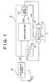
- Fig. 1 shows a schematic configuration of the electronic throttle controller.
- the electronic throttle control system comprises an electronic throttle 1 and an electronic control unit (ECU) 2 for controlling the electronic throttle 1.
- the electronic throttle 1 adjusts output of an automotive engine (not shown in the drawing), and detects an actual opening amount of a throttle valve 4 with a throttle sensor 6 by opening and closing the throttle valve 4, provided in a bore 3 of a throttle body constituting an intake path of the engine, by a motor 5 which is an actuator.
- the throttle valve 4 is of link-less type which is not mechanically interlocked with the operation of an accelerator pedal 7. That is to say, the throttle valve 4 opens and closes in response to driving force of the motor 5 controlled by the ECU 2 based on the operating amount of the accelerator pedal 7 which is detected by an accelerator sensor 8.
- the throttle valve 4 is rotatably supported by a throttle shaft 9 which extends through the bore 3 of the throttle body.
- the motor 5 is provided at one end of the throttle shaft 9 and the throttle sensor 6 is provided at the other end thereof.
- the motor 5 is a torque motor. This motor 5 has a characteristic in which it determines the opening amount of the throttle valve 4 according to a duty ratio by PWM control.
- the throttle sensor 6 comprises, for example, a potentiometer.
- the accelerator sensor 8 detects the operating amount of the accelerator pedal 7 by a driver as a target opening amount TAR in order to set the target opening amount TAR of the throttle valve 4, and thus function to set the target opening amount.
- This sensor 8 comprises, for example, a potentiometer.
- the ECU 2 includes a microcomputer 11, an A/D converter 12, and a drive circuit 13.
- the microcomputer 11 administers control of the electronic throttle 1 and functions as current control means, duty ratio calculating means, and averaging means according to the invention.
- the microcomputer 11 includes, as is generally known, a central processing unit (CPU), random access memory (RAM), read only memory (ROM), and the like.
- the ROM stores a control program relating to the electronic throttle 1.
- the A/D converter 12 converts an analog signal output from the throttle sensor 6 into a digital signal, which it outputs to the microcomputer 11.
- the drive circuit 13 receives the control current output from the microcomputer 11 and outputs a drive current to the motor 5.
- an analog signal corresponding to an actual opening amount VTA output from the throttle sensor 6 is converted to a digital signal by the A/D converter 12, and that signal is input to the microcomputer 11.
- An analog signal according to a target opening amount TAR output from the accelerator sensor 8 is directly input to the microcomputer 11.
- the microcomputer 11 controls the motor 5 by processing input signals according to the actual opening amount VTA and the target opening amount TAR based on the Proportional Integral Derivative Control (PID control) method.
- PID control Proportional Integral Derivative Control
- the microcomputer 11 calculates the opening deviation VER of the actual opening amount VTA with respect to the target opening amount TAR based on a value of each input signal, and calculates a value of a control amount VPID using a predetermined formula based on the value of the opening deviation VER.
- the microcomputer 11 outputs the drive current corresponding to the value of that control amount VPID to the motor 5 via the drive circuit 13 to control the coil current of the motor 5.
- the driving amount of the motor 5 is controlled to make the actual opening amount VTA of the throttle valve 4 approximate the target opening amount TAR.
- the electronic throttle control system of this embodiment upon failure of the throttle sensor 6, the control of the electronic throttle 1 during a failure is executed by performing open-loop control on the motor 5 by PWM control based on the target opening amount TAR detected by the accelerator sensor 8.
- FIG. 2 is a flowchart illustrating the content of a program for control during a failure executed by the microcomputer 11.
- the microcomputer 11 periodically executes this routine at predetermined intervals.
- Step 100 the microcomputer 11 calculates a value of duty ratio DUTY corresponding to a target opening amount TAR detected by the accelerator sensor 8.
- the duty ratio DUTY refers to the ratio Dn of an excitation width of an on-pulse which is periodically controlled in one cycle T by PWM control.
- the microcomputer 11 calculates the duty ratio DUTY with an accuracy higher than its own output resolution LDT by 1 LSB (least significant bit).
- Step 110 the microcomputer 11 determines whether or not the least significant bit LSB of a value of the calculated duty ratio DUTY is 1. If the least significant bit LSB is 1, the microcomputer 11 sets, in Step 120, an averaging requirement flag XVA to 1 to increase its own output resolution.
- the microcomputer 11 sets the averaging requirement flag XVA to 0 in Step 130, and sets a timing flag XT to 0 in Step 135.
- Step 140 determines in Step 140 whether or not the averaging requirement flag XVA is 1. If the flag XVA is not 1, the microcomputer 11 proceeds to the process in Step 180.
- Step 150 if the averaging requirement flag XVA is 1, averaging of the duty ratio DUTY by PWM control is required, and therefore the microcomputer 11 proceeds to the process in Step 150.
- Step 150 the microcomputer 11 determines whether or not the timing flag XT is 1. If the timing flag XT is not 1, the microcomputer 11 calculates, in Step 160, the duty ratio DUTY by adding only 1 LSB, as the output resolution LDT of the microcomputer 11, to the calculated duty ratio DUTY. Thereafter, in Step 165, the microcomputer 11 sets the timing flag XT to 1 such that the process of Step 160 will not be executed the next time.
- Step 150 the microcomputer 11 sets, in Step 170, the timing flag XT to 0 such that the process in Step 160 is executed the next time.
- Step 180 after going through Step 140, 165, or 170, the microcomputer 11 sets a value for which the current calculated duty ratio DUTY is shifted to the right by 1 bit as an output duty ratio DOUT. That is to say, by truncating the lowest bit of the calculated duty ratio DUTY, the accuracy is adjusted to the output resolution LDT of the microcomputer 11.
- Step 190 the microcomputer 11 outputs the control current of duty waveform to the drive circuit 13 according to a value of the set output duty ratio DOUT, and terminates the routine temporarily, after which it is started again.
- the control current of duty waveform in which the required ratio Dn in one cycle T is the duty ratio DUTY is periodically output to the drive circuit 13 as shown in Fig. 3.
- the control current having a waveform in which the required ratio Dn (i.e., on-pulse duration) in one cycle T is the duty ratio DUTY and the output resolution LDT of the microcomputer 11 is added to every other duty ratio Dn is periodically output to the drive circuit 13 as shown in Fig. 4.
- the fact that the least significant bit LSB of the duty ratio DUTY is 1 means that the fraction of 0.5 ⁇ s is required. Therefore, as shown in Fig.
- adding a value having the output resolution LDT to every other on-pulse having the specified ratio Dn means that the ration-pulse in which 1 LSB is added to the specified ratio Dn is output alternately with the ration-pulse in which 1 LSB is not added to the specified ratio Dn. That is to say, an on-pulse in which 1 ⁇ s and 0 ⁇ s are added alternately to the required ratio Dn is output periodically, and thus as a whole, this is equivalent to periodically outputting an on-pulse in which an average of 0.5 ⁇ s is added.
- open-loop control is performed on the motor 5 by PWM control based on a target opening amount TAR set by the accelerator sensor 8 in order to control opening of the electronic throttle 1.
- the microcomputer 11 controls the current output to the motor 5 via the drive circuit 13 by periodically controlling an excitation width of an on-pulse with the required duty ratio DUTY
- the microcomputer 11 calculates the duty ratio DUTY corresponding to the set target opening amount TAR with an accuracy higher than the output resolution LDT of the microcomputer 11. Then, when the value of the calculated duty ratio DUTY exceeds that of the output resolution LDT, the value of the output resolution LDT of the microcomputer 11 is added to every other required ratio Dn which is the value of the duty ratio DUTY, and thereby the current output to the motor 5 is averaged and increased only by the value added.
- a control resolution of the motor 5 increases only by the amount of increased current output to the motor 5, and the electronic throttle 1 is controlled with a resolution that much higher. Accordingly, the opening amount of the electronic throttle 1 can be controlled with a higher resolution using the present hardware configuration without making the microcomputer more sophisticated or changing the bore 3 of the throttle body to be non-linear. Particularly, only when the duty ratio DUTY calculated according to the target opening amount TAR exceeds a value of the output resolution LDT of the microcomputer 11, can the opening amount be controlled with a higher resolution according to the requirement of that target opening amount TAR.
- the output resolution LDT of the microcomputer generally used in engine control is about 4 ⁇ s to 1 ⁇ s, which is not sufficient for the required resolution.
- the throttle requirement resolution may be increased by making the microcomputer 11 more sophisticated or making the bore 3 of the throttle body non-linear.
- the throttle requirement resolution may be increased by making the microcomputer 11 more sophisticated or making the bore 3 of the throttle body non-linear.
- the electronic throttle control system and method of this embodiment calculates the duty ratio DUTY with an accuracy twice the output resolution LDT of the microcomputer 11.
- PWM control for the output exceeding the output resolution LDT of the microcomputer 11, an on-pulse in which a value of the output resolution is added to a value of the required duty ratio is output every other output.
- the configuration of the content of a program for control during a failure differs from that in the first embodiment.
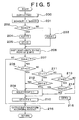
- the content of the control program is shown in the flowchart of Fig. 5.
- Step 200 the microcomputer 11 calculates a value of the duty ratio DUTY corresponding to a target opening amount TAR detected by the accelerator sensor 8.
- the microcomputer 11 calculates the duty ratio DUTY with an accuracy higher than the output resolution LTD only by 2 LSB.
- Step 201 the microcomputer 11 substitutes 0 for every bit of the calculated duty ratio DUTY except the lowest two bits. Accordingly, the part of information (fraction) that exceeds the output resolution LDT of the microcomputer 11 is substituted for processing data D0.
- Step 202 the microcomputer 11 determines whether or not the processing data D0 is 0. If the processing data D0 is not 0, i.e., if there is a fraction in the processing data D0, the microcomputer 11 sets the averaging requirement flag XVA to 1 in Step 203 to increase its own output resolution LDT.
- the microcomputer 11 sets the averaging requirement flag XVA to 0 in Step 204 and clears a timing counter CT to 0 in Step 205.
- Step 206 after going through Step 203 or 205, the microcomputer 11 sets a value for which the current calculated duty ratio DUTY is shifted to the right by two bits as the output duty ratio DOUT. That is to say, by truncating the lowest two bits of a value of the current calculated duty ratio DUTY, a value of the duty ratio DUTY in accordance with an accuracy of the output resolution LDT of the microcomputer 11 is substituted for the output duty ratio DOUT.
- step S207 the microcomputer 11 determines whether or not the averaging requirement flag XVA is 1. If the flag XVA is not 1, the microcomputer 11 proceeds to the process in Step 216.
- averaging requirement flag XVA 1
- averaging of quarterly decomposition process is required for the duty ratio DUTY by PWM control so the microcomputer 11 proceeds to the process in Step 208.
- Step 208 the microcomputer 11 determines whether or not the timing counter CT is 0. If the timing counter CT is 0, the microcomputer 11 calculates, in Step 209, the output duty ratio DOUT by adding 1 LSB, which is a value of the output resolution LDT of the microcomputer 11, to the calculated output duty ratio DOUT.
- Step 210 the microcomputer 11 increases the timing counter CT by 1 and proceeds to the process in Step 216.
- Step 208 the microcomputer 11 determines whether or not the timing counter CT is 1 in Step 211. If the timing counter CT is 1, the microcomputer 11 proceeds to the process in Step 212.
- Step 212 the microcomputer 11 determines whether or not the processing data D0 is 2 or greater. If the processing data D0 is 2 or greater, i.e., 2 or 3, the microcomputer 11 proceeds to the process in Step 209. However, if the processing data D0 is less than 2, i.e., if it is 1, the microcomputer 11 proceeds to the process in Step 210.
- the microcomputer 11 determines whether or not the timing counter CT is 2 in Step 213. If the timing counter CT is 2, the microcomputer 11 proceeds to the process in Step 214.
- Step 214 the microcomputer 11 determines whether or not the processing data D0 is 3 or greater. If the processing data D0 is 3 or greater, i.e., if it is 3, the microcomputer 11 proceeds to the process in Step 209. On the other hand, if the processing data D0 is less than 3, i.e., 1 or 2, the microcomputer 11 proceeds to the process in Step 210.
- Step 213 the microcomputer 11 clears the timing counter CT to 0 in Step 215 and proceeds to the process in Step 216.
- Step 216 after going through Step 207, 210, or 215, the microcomputer 11 outputs a duty waveform to the drive circuit 13 according to a value of the set output duty ratio DOUT and terminates the routine temporarily, after which it is started again.
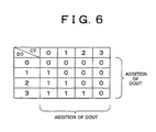
- the relationship of addition of the processing data D0, the timing counter CT, and the output duty ratio DOUT can be obtained as shown in the table of Fig. 6. That is to say, when the processing data D0 is 0 (actually the timing counter CT does not operate when the processing data D0 is 0), 1 is not added to the output duty ratio DOUT at any timing where the timing counter CT is 0 to 3. When the processing data D0 is 1, 1 is added to the output duty ratio DOUT only at a timing where the timing counter CT is 0. When the processing data D0 is 2, 1 is added to the output duty ratio DOUT at a timing where the timing counter CT is 0 or 1.
- open-loop control is performed on the motor 5 by PWM control based on a target opening amount TAR set by the accelerator sensor 8 in order to control the opening amount of the electronic throttle 1.
- the microcomputer 11 controls the current output to the motor 5 via the drive circuit 13 by periodically controlling an excitation width of an on-pulse with a required duty ratio DUTY.
- the microcomputer 11 calculates the duty ratio DUTY corresponding to the set target opening amount TAR with an accuracy higher than the output resolution LDT of the microcomputer 11 by 2 LSB. Then, by adding a value of the output resolution LDT of the microcomputer 11 to the required ratio Dn, which is a value of the duty ratio DUTY, at a timing according to a difference in values of the processing data D0 representing a fraction in the calculated duty ratio DUTY, the current output to the motor 5 is averaged and increased only by the value added.
- a value of the output resolution LDT of the microcomputer 11 is added to the required ratio Dn, which is the duty ratio DUTY, every other cycle; however, it may be added every two or four cycles.
- An electronic throttle control system performs open-loop control on a motor (5) of an electronic throttle (1) by pulse width modulation (PWM) control based on a target opening amount TAR set by an accelerator sensor (8).
- a microcomputer (11) controls the current output to the motor (5) by periodically controlling an excitation width of an on-pulse with a specified duty ratio.
- the microcomputer (11) calculates a duty ratio corresponding to the set target opening amount TAR with an accuracy higher than its own resolution. When the calculated duty ratio exceeds a value of the output resolution, the microcomputer (11) adds, e.g., every other cycle, a value having the output resolution to the duty ratio of the on-pulse which is periodically controlled, and averages the current output to the motor (5).
Landscapes
- Engineering & Computer Science (AREA)
- Chemical & Material Sciences (AREA)
- Combustion & Propulsion (AREA)
- Mechanical Engineering (AREA)
- General Engineering & Computer Science (AREA)
- Electrical Control Of Air Or Fuel Supplied To Internal-Combustion Engine (AREA)
- Combined Controls Of Internal Combustion Engines (AREA)
- Control Of Throttle Valves Provided In The Intake System Or In The Exhaust System (AREA)
Applications Claiming Priority (2)
| Application Number | Priority Date | Filing Date | Title |
|---|---|---|---|
| JP2000314685 | 2000-10-16 | ||
| JP2000314685A JP2002122036A (ja) | 2000-10-16 | 2000-10-16 | 電子スロットル制御装置 |
Publications (1)
| Publication Number | Publication Date |
|---|---|
| EP1199455A2 true EP1199455A2 (fr) | 2002-04-24 |
Family
ID=18793891
Family Applications (1)
| Application Number | Title | Priority Date | Filing Date |
|---|---|---|---|
| EP01124597A Withdrawn EP1199455A2 (fr) | 2000-10-16 | 2001-10-15 | Système et méthode de commande électronique de papillon |
Country Status (3)
| Country | Link |
|---|---|
| US (1) | US20020043242A1 (fr) |
| EP (1) | EP1199455A2 (fr) |
| JP (1) | JP2002122036A (fr) |
Cited By (2)
| Publication number | Priority date | Publication date | Assignee | Title |
|---|---|---|---|---|
| GB2386438A (en) * | 2002-03-07 | 2003-09-17 | Visteon Global Tech Inc | Electronic throttle control with increased resolution |
| EP2768137A4 (fr) * | 2011-10-13 | 2015-06-03 | Mitsubishi Hitachi Power Sys | Dispositif de génération d'impulsions et procédé de génération d'impulsions |
Families Citing this family (6)
| Publication number | Priority date | Publication date | Assignee | Title |
|---|---|---|---|---|
| JP4012654B2 (ja) * | 1999-08-06 | 2007-11-21 | 株式会社日立製作所 | エンジン機器制御装置及び電子制御スロットルシステム |
| US6918373B1 (en) | 2004-03-17 | 2005-07-19 | Visteon Global Technologies, Inc. | Single wire control method for electronic throttle systems |
| JP4428163B2 (ja) * | 2004-07-20 | 2010-03-10 | 株式会社デンソー | バルブ位置制御装置 |
| US8204662B2 (en) * | 2008-02-28 | 2012-06-19 | Cnh America Llc | Method and system to control electronic throttle sensitivity |
| US9116787B1 (en) * | 2012-06-27 | 2015-08-25 | Marden Industries, Inc. | Electronic control system for mobile heavy equipment machinery |
| CN111255586B (zh) * | 2020-01-22 | 2021-05-11 | 东风汽车集团有限公司 | 一种电子节气门复位弹簧力和摩擦力的自学习方法 |
-
2000
- 2000-10-16 JP JP2000314685A patent/JP2002122036A/ja active Pending
-
2001
- 2001-10-10 US US09/972,948 patent/US20020043242A1/en not_active Abandoned
- 2001-10-15 EP EP01124597A patent/EP1199455A2/fr not_active Withdrawn
Cited By (5)
| Publication number | Priority date | Publication date | Assignee | Title |
|---|---|---|---|---|
| GB2386438A (en) * | 2002-03-07 | 2003-09-17 | Visteon Global Tech Inc | Electronic throttle control with increased resolution |
| US6672282B2 (en) | 2002-03-07 | 2004-01-06 | Visteon Global Technologies, Inc. | Increased resolution electronic throttle control apparatus and method |
| GB2386438B (en) * | 2002-03-07 | 2004-05-19 | Visteon Global Tech Inc | Increased resolution electronic throttle control |
| EP2768137A4 (fr) * | 2011-10-13 | 2015-06-03 | Mitsubishi Hitachi Power Sys | Dispositif de génération d'impulsions et procédé de génération d'impulsions |
| US9252762B2 (en) | 2011-10-13 | 2016-02-02 | Mitsubishi Hitachi Power Systems, Ltd. | Pulse generation device and pulse generation method |
Also Published As
| Publication number | Publication date |
|---|---|
| US20020043242A1 (en) | 2002-04-18 |
| JP2002122036A (ja) | 2002-04-26 |
Similar Documents
| Publication | Publication Date | Title |
|---|---|---|
| US6253733B1 (en) | Electronic throttle valve control apparatus | |
| US5245966A (en) | Control system for a drive unit in motor vehicle | |
| US5818178A (en) | Valve control apparatus for an automobile | |
| JPWO2001007768A1 (ja) | モータ駆動式スロットル弁制御装置、及びその制御方法、自動車、及び自動車のスロットル弁駆動用モータの温度測定方法、モータの温度測定方法 | |
| EP0810143A2 (fr) | Procédé et appareil pour contrÔler un système de direction assistée électrique par linéarisation d'amplification de système de couple d'entrée/de sortie | |
| US20040254656A1 (en) | Method and device for filtering a signal | |
| US20030084873A1 (en) | Electronic throttle control apparatus | |
| US7150263B2 (en) | Engine speed control apparatus; engine system, vehicle and engine generator each having the engine speed control apparatus; and engine speed control method | |
| US5947086A (en) | Throttle valve control apparatus | |
| US4982710A (en) | Electronic throttle valve opening control method and system therefor | |
| EP1199455A2 (fr) | Système et méthode de commande électronique de papillon | |
| US5161505A (en) | Method and arrangement for detecting measured values in motor vehicles | |
| US6318337B1 (en) | Electronic throttle control | |
| JP3993659B2 (ja) | 内燃機関の設定要素の制御方法および装置 | |
| JPH08303285A (ja) | 自動車用バルブ制御装置及び制御方法 | |
| JPH03237241A (ja) | エンジンのアイドル回転数制御装置 | |
| US7032570B2 (en) | Electronic throttle control device for engine | |
| US7222605B2 (en) | Throttle control system and method | |
| JP2008204125A (ja) | 電子制御装置及びフィードバック制御方法 | |
| US6205976B1 (en) | Method and arrangement for controlling an operating variable of a motor vehicle | |
| US20010029422A1 (en) | Method and arrangement for controlling the drive unit of a vehicle | |
| JPH0942032A (ja) | 内燃機関のスロットル制御装置 | |
| JP3041156B2 (ja) | 内燃機関の絞り弁制御装置 | |
| US20040107038A1 (en) | Torque controller of internal combustion engine | |
| US5400756A (en) | Control method and control arrangement for an adjusting device in a motor vehicle |
Legal Events
| Date | Code | Title | Description |
|---|---|---|---|
| PUAI | Public reference made under article 153(3) epc to a published international application that has entered the european phase |
Free format text: ORIGINAL CODE: 0009012 |
|
| 17P | Request for examination filed |
Effective date: 20011015 |
|
| AK | Designated contracting states |
Kind code of ref document: A2 Designated state(s): AT BE CH CY DE DK ES FI FR GB GR IE IT LI LU MC NL PT SE TR |
|
| AX | Request for extension of the european patent |
Free format text: AL;LT;LV;MK;RO;SI |
|
| STAA | Information on the status of an ep patent application or granted ep patent |
Free format text: STATUS: THE APPLICATION HAS BEEN WITHDRAWN |
|
| 18W | Application withdrawn |
Effective date: 20030613 |
|
| R18W | Application withdrawn (corrected) |
Effective date: 20030613 |