EP1200143B2 - Spritzenkolbenstangen-Antriebssystem zum Erfassen von unterschiedlichen Kolbenstangengrößen und Verfahren - Google Patents
Spritzenkolbenstangen-Antriebssystem zum Erfassen von unterschiedlichen Kolbenstangengrößen und Verfahren Download PDFInfo
- Publication number
- EP1200143B2 EP1200143B2 EP00950543A EP00950543A EP1200143B2 EP 1200143 B2 EP1200143 B2 EP 1200143B2 EP 00950543 A EP00950543 A EP 00950543A EP 00950543 A EP00950543 A EP 00950543A EP 1200143 B2 EP1200143 B2 EP 1200143B2
- Authority
- EP
- European Patent Office
- Prior art keywords
- plunger
- arms
- syringe
- lever
- pushing surface
- Prior art date
- Legal status (The legal status is an assumption and is not a legal conclusion. Google has not performed a legal analysis and makes no representation as to the accuracy of the status listed.)
- Expired - Lifetime
Links
- 238000000034 method Methods 0.000 title claims description 10
- 230000003213 activating effect Effects 0.000 claims abstract description 5
- 230000033001 locomotion Effects 0.000 description 28
- 230000007246 mechanism Effects 0.000 description 19
- 239000012530 fluid Substances 0.000 description 8
- 230000009471 action Effects 0.000 description 4
- 230000006835 compression Effects 0.000 description 4
- 238000007906 compression Methods 0.000 description 4
- 230000004913 activation Effects 0.000 description 3
- 238000001802 infusion Methods 0.000 description 3
- 230000000994 depressogenic effect Effects 0.000 description 2
- 238000013461 design Methods 0.000 description 2
- 230000000694 effects Effects 0.000 description 2
- 239000007924 injection Substances 0.000 description 2
- 238000002347 injection Methods 0.000 description 2
- 238000003780 insertion Methods 0.000 description 2
- 230000037431 insertion Effects 0.000 description 2
- 238000009434 installation Methods 0.000 description 2
- 230000000717 retained effect Effects 0.000 description 2
- 230000004308 accommodation Effects 0.000 description 1
- 238000013459 approach Methods 0.000 description 1
- 230000008859 change Effects 0.000 description 1
- 238000010586 diagram Methods 0.000 description 1
- 239000003814 drug Substances 0.000 description 1
- 210000004124 hock Anatomy 0.000 description 1
- 230000006872 improvement Effects 0.000 description 1
- 239000003978 infusion fluid Substances 0.000 description 1
- 239000007788 liquid Substances 0.000 description 1
- 238000012986 modification Methods 0.000 description 1
- 230000004048 modification Effects 0.000 description 1
- 238000012544 monitoring process Methods 0.000 description 1
- 230000003287 optical effect Effects 0.000 description 1
- 230000004044 response Effects 0.000 description 1
- 238000012163 sequencing technique Methods 0.000 description 1
Images


Classifications
-
- A—HUMAN NECESSITIES
- A61—MEDICAL OR VETERINARY SCIENCE; HYGIENE
- A61M—DEVICES FOR INTRODUCING MEDIA INTO, OR ONTO, THE BODY; DEVICES FOR TRANSDUCING BODY MEDIA OR FOR TAKING MEDIA FROM THE BODY; DEVICES FOR PRODUCING OR ENDING SLEEP OR STUPOR
- A61M5/00—Devices for bringing media into the body in a subcutaneous, intra-vascular or intramuscular way; Accessories therefor, e.g. filling or cleaning devices, arm-rests
- A61M5/14—Infusion devices, e.g. infusing by gravity; Blood infusion; Accessories therefor
- A61M5/142—Pressure infusion, e.g. using pumps
- A61M5/145—Pressure infusion, e.g. using pumps using pressurised reservoirs, e.g. pressurised by means of pistons
- A61M5/1452—Pressure infusion, e.g. using pumps using pressurised reservoirs, e.g. pressurised by means of pistons pressurised by means of pistons
- A61M5/1456—Pressure infusion, e.g. using pumps using pressurised reservoirs, e.g. pressurised by means of pistons pressurised by means of pistons with a replaceable reservoir comprising a piston rod to be moved into the reservoir, e.g. the piston rod is part of the removable reservoir
Definitions
- the invention is related generally to drive mechanisms for medical infusion pumps, and more particularly, to a system and method for retaining the plunger of a fluid container at the drive mechanism.
- a syringe pump having a lead screw and a screw drive mechanism which translates the rotational motion of the lead screw into linear motion.
- a syringe plunger driver is connected to the screw drive mechanism for connecting the linear motion of the screw drive mechanism to the syringe plunger to empty the syringe.
- Many screw drive mechanisms include a disengagement mechanism that the operator uses to disengage the lead screw drive mechanism from the lead screw threads. Once disengaged, the operator may move the plunger driver along the lead screw to the position of the extended syringe plunger, and then engage both the syringe plunger with the plunger driver and the lead screw drive mechanism with the threads of the lead screw at the new position. It is desirable that this disengagement mechanism and this plunger driver mechanism be easy to use to facilitate operator usage of the pump.
- syringes vary in size among manufacturers. Even syringes designed to contain the same quantity of fluid can vary substantially in outer dimensions of both length and diameter from manufacturer to manufacturer. In some prior pumps, only a single syringe from a single manufacturer could be used, thereby greatly restricting the usefulness of the pump. When that particular syringe type was not available, the pump could not be used. Pumps were also developed that could receive different sized syringes; however, obstacles still exist. Not only can syringe barrel diameters vary from syringe to syringe, but also the length of the syringe barrel, the plunger length, the plunger flange diameter, and thickness of the plunger flange can all vary. All of these physical variables would have to be considered when designing a plunger driver system for a syringe pump if that pump is to be capable of handling syringes of differing capacities from a variety of manufacturers.
- the driver In a syringe pump plunger driver, the driver typically engages the plunger flange and holds that flange in a fixed relationship with a pushing surface which is part of the plunger driver. The pushing surface contacts the plunger flange and applies force to move the plunger flange into the syringe to expel the syringe contents.
- Some plunger drivers include a retainer structure that operates as an anti-siphon feature to prevent the plunger from moving into the barrel and emptying the syringe at a rate in excess of the programmed movement rate of the pushing surface when under a negative pressure condition downstream.
- a plunger driver system is needed which will precisely hold each syringe in correct alignment with the pushing surface of the plunger driver.
- the system must also assure that the plunger will be firmly held in the plunger driver and that the plunger detector system will detect the presence and absence of a syringe and provide an alarm in the case of a dislodged or absent plunger. Additionally, it would be desirable if such a system were easy to use.
- the syringe plunger flange is retained well but due to the configuration of the driver system, loading the syringe is often awkward.
- the "sprung plate” a plate is mounted to the plunger drive head and is intended to trap the syringe plunger flange between itself and the pushing surface of the plunger drive.
- loading the syringe properly for this design is not intuitive.
- operators attempt to load the syringe barrel first and then try to load the plunger. Difficulty is encountered when trying to load the plunger in this sequence as the plunger stem must now be forced outwards in order to locate the plunger flange behind the sprung plate. This in turn requires some movement of the syringe barrel; however, there is a barrel clamp over the syringe barrel which has a bias device trying to prevent this very movement.
- a plunger drive system and method that are capable of handling different sizes of syringes while still presenting a relatively easy system to use to the operator of the pump.
- Such a system and method should provide a mechanism to align, firmly engage, and detect the presence of the plunger of each of the syringes specified for the pump. Further, such a system and method should be capable of resisting siphoning of the syringe contents from syringes of all sizes usable in the pump. The invention fulfils these needs and others.
- EP0916353 which is used as a basis for the preamble of claims 1 and 10, discloses a liquid infusion apparatus incorporating a pressing device for pressing a flange of a syringe plunger against a slider to retain the plunger flange in contact with the slider, thus resisting undesired siphoning effects.
- the configuration of the holding arms and slider is such that varying thicknesses of the plunger flange may be accommodated. However, the holding arms do not contact the plunger stem when in their operative holding position.
- EP0323321 discloses an apparatus permitting the use of various types of syringes for single or multiple injection, the apparatus consisting of a mechanism incorporating two jaws which move symmetrically relative to the axis of the syringe and whose spacing apart allows the injection to be stopped in the event of occlusion, independently of the diameter of the syringe used.
- the support is additionally arranged in such a way as to hold different types of syringe in the same reference axis which is common to that with the device for pushing the syringe plunger.
- JP 09-122237 discloses a syringe pump having left and right hocks which pinch and hold a syringe plunger.
- the present invention is directed to a system and method for driving a syringe plunger while resisting siphoning.
- the system and method in accordance with the invention permit the use of syringes of different sizes as well as facilitating the loading of a syringe.
- the arms are spring loaded towards the pushing surface by means of a first bias device connected to the arms, and the arms are spring loaded inwardly by means of a second bias device connected to the arms.
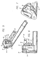
- FIG. 1 a perspective view of a syringe pump 10 having a plunger driver system in accordance with the principles of the invention.
- a syringe 12 is shown next to the pump rather than mounted in the pump, for clarity of illustration, with arrows indicating the mounting locations.
- the syringe pump includes a syringe cradle 14 in which the syringe barrel 16 will rest.
- the syringe barrel flange 18 will be located in a barrel flange groove 20 in the pump 10 to immobilize the syringe barrel from longitudinal movement during movement of the syringe plunger 22 within the barrel.
- the syringe plunger flange 24, having an inner side 25, is interconnected with a syringe piston 26 by a syringe plunger stem 28.
- the plunger flange 24 When mounted in the syringe pump 10 properly, the plunger flange 24 is held in a plunger drive head 30 with a pair of pivotally mounted plunger retaining arms 32, shown in the closed position in FIG. 1 .
- a disengagement lever 34 is used to disengage the plunger drive head 30 from the threads of a lead screw (not shown) as well as control the positions of the retaining arms 32 to allow removal and insertion of a syringe plunger flange 24.
- Disengaging the plunger drive head 30 from the threads of the lead screw permits the operator to move the plunger drive head 30 along the lead screw to the correct position to capture the plunger flange of a new syringe 12.
- syringes may be provided for use with a syringe pump with different quantities of fluid and the plunger may be located at different positions in relation to the barrel.
- the ability to manually move the drive head 30 permits the accommodation of syringes with different beginning plunger positions.
- the drive head 30 also includes a pushing surface 36 on which the plunger flange 24 will rest as the drive head 30 moves forward toward the plunger barrel 16 pushing the plunger 22 into the barrel 16 of the syringe to expel the syringe contents through an administration tubing 38 to the patient. Also included in this embodiment of a plunger drive head is a detector button 40 used to detect the presence of a syringe. When the button 40 is depressed, circuitry within the drive head 30 indicates to a pump processor (not shown) that a syringe is present thereby enabling operation of the pump.
- the pump will not operate if the detector 40 has not been depressed, as may happen with a mis-loaded syringe, or a syringe that has become dislodged.
- a control panel 42 comprising multiple buttons 44 for control over the pump 10 as well as a display 46 used to present pump specific information to the operator.
- the buttons may allow the operator to program the pump for the flow rate, the volume to be infused, and other pump parameters.
- the display may present the programmed flow rate, the amount of fluid remaining to be infused, as well as alarms and other information.
- the cradle 14 of the pump 10 has a V-shape with an approximate 120° included angle. Syringes inserted in the cradle 14 will all align with the plunger driver 30 within a particular vertical range. The points where the longitudinal center lines of the syringes intersect the plunger driver will change according to the size of the syringe but only in one direction 47 along the drive head 30.
- the plunger drive head 30 is shown in the open configuration where the retainer arms 32 have been moved outward (pivoted away from each other) and forward (longitudinally toward the syringe cradle 14 or the barrel 16 of a syringe if one is mounted in the pump). In this position or configuration, the drive head 30 is ready to accept a syringe plunger. Shown more clearly in FIG. 2 is the drive tube 50 that extends in one piece from the drive head 30 to a point within the body of the pump 10. This extended length serves to prevent spilled or leaking fluids from reaching the lead screw.
- FIG. 3 presents a rear view of the drive head 30 shown in FIG. 2 .
- the lever 34 has been moved to a first position causing the retainer arms 32 to be in the open position shown in FIG. 2 .
- the lever 34 has been moved fully into a first stop 52.
- FIG. 4 a side view of both FIGS. 2 and 3 , it can be seen that the arms 32 have also moved forward when they are in the open position.
- the plunger detector button 44 is also shown in the extended position.
- a spring mounted internally to the drive head 30 is used to bias the detector button 44 outward.
- An optical sensor determines the presence and absence of a syringe plunger flange at the plunger drive head 30 by monitoring the position of the button 44.
- a syringe plunger detector system such as that shown and described here see U.S. Patent No. 5,545,140 .
- the button 44 is completely forward indicating the absence of a plunger flange.
- FIG. 4 Another feature shown in FIG. 4 is the bevel formed into the top of the button 44.
- This bevel aids in syringe insertion into the pump 10 by allowing vertical motion during installation.
- the syringe plunger flange would strike the bevel causing the button 44 to depress somewhat while the syringe is being loaded.
- the syringe would have to be loaded more in a horizontal manner into the plunger drive head 30.
- the syringe may be loaded either horizontally or vertically thus making operator use of the pump easier.
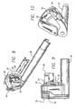
- the drive head 30 is shown in a partially closed configuration.
- the arms have pivoted inward, toward each other, to capture the plunger stem 28 between themselves to retain the syringe plunger in the correct radial position.
- the lever 34 has been moved off the first stop 52 but has not been moved entirely over to a second stop 54.
- the arms have captured the plunger stem, but as shown in FIG. 6 , they are not yet in contact with the plunger flange 24. There is still a space between the inside surfaces 31 of the arms 32 and the plunger flange as in FIG. 4 .
- FIG. 7 shows the intermediate position of the lever more clearly.
- the lever is not midway between the first and second stops 52 and 54, but is closer to the second stop. In one embodiment, the lever does not cause the arms 32 to move toward the pushing surface until the last five degrees of movement of the lever 34.
- the arms 32 are self-adjusting to the size of plunger mounted in the pump. The arms 32 are spring loaded inward to provide a substantial clamping force against the stem of the plunger and as a result of that clamping force and the fact that sequencing of the arm movements is such that the arms close first before returning in the direction of the pushing surface, the plunger stem is first centered by the arms, and then is brought into contact with the pushing surface. Thus alignment of the plunger stem and flange is first obtained.
- FIGS. 8, 9, and 10 the closed configuration of the drive head 30 is shown.
- the arms 32 not only have the arms 32 captured the plunger stem 28 between themselves to retain the stem in the correct radial position (centered), but the inside surfaces 31 of the arms have also come into contact with the inside surface 25 of the plunger flange 24 to exert a clamping force against the flange towards the pushing surface ( FIG. 9 ).
- the arms 32 provide a substantial clamping force against the inner side of the plunger flange to hold it constantly in contact with the pushing surface 36, thereby resisting siphoning.
- spring loading of the arms is responsible for the force exerted by the arms against the plunger flange 24 to retain it in contact with the pushing surface.
- FIGS. 11 through 18 present the operation of the arms in the longitudinal direction; i.e., toward the syringe barrel 16 and in the opposite direction, toward the pushing surface 36.
- an arm 32 is shown at its rest position. It is in contact with the pushing surface 36 or is a short distance away, that distance being less than the thickness of any known syringe flange that may be used in the pump.
- the arm 32 is biased into its rest position by a compression spring 56.
- An actuation plate 58 is in contact with the proximal end 60 of the arm and has a protrusion 59 on its surface away from the arm. The actuation plate moves towards and away from the pushing surface 36.
- An actuator driver 62 is in contact with the actuation plate 58 in FIG. 11 and moves laterally in relation to that plate 58, as is shown in FIGS. 12 through 18 .
- the actuation driver 62 includes a ramp 64 for contacting the protrusion 59 of the actuation plate 58.
- a latch 66 is biased towards the actuation plate 58 and is shown touching the plate 58 in FIG. 11 but is not engaged with it.
- the lever 34 ( FIG. 10 ) is coupled to the actuation driver 62 and the driver moves with the movement of the lever.
- FIGS. 12 through 15 show the operation of the mechanism on the arm.
- the ramp 64 of the driver approaches the protrusion 59 of the actuation plate ( FIG. 12 ), contacts the protrusion, and begins to extend the arm toward the syringe barrel, away from the pushing surface ( FIGS. 13 and 14 ) thereby compressing the biasing spring 56.
- the actuation driver 62 and arm have moved far enough so that the protrusion 59 of the actuation plate 58 is at the top of the ramp 64 as shown in FIG. 15 , the latch engages the actuation plate.
- the ramp 64 of the actuation driver 62 loses contact with the protrusion 59 of the actuation plate 58 due to the engagement of the latch 66 with the actuation plate.
- the arms 32 remain in position during a large amount of movement of the actuation driver 62 as shown in FIGS. 16 and 17 , the arms are rotating inward, as will be discussed below.
- the actuation driver 62 has been moved far enough to the left, it contacts the latch ( FIG. 17 ) and finally pushes the latch out of engagement with the actuation plate 58 in FIG. 18 .
- the spring 56 of the arm then moves the arm 32 toward the pushing surface 36 and into contact with any syringe plunger flange that may be present. Additionally, the actuation plate 58 is once again in contact with the actuation driver 62. In the embodiment discussed above, the actuation driver 62 contacts the latch only in the last five degrees of movement of the lever. Thus the arms 32 are latched in the forward position until the last five degrees of movement of the lever 34.
- the lever 34 is connected to a mounting shaft 68, and has an actuation rod 70 captured within a slot 72 formed in an arms driver 74.
- An extension spring 76 biases the lever toward the right or closed position.
- Each of the arms (not shown) is connected to an arm drive gear 78 and 80.
- One of the drive gears 78 is biased by a bias extension spring 82 that tends to move the arm to the closed position ( FIG. 1 ).
- FIGS. 20 through 24 the self-adjusting feature of the arms will be seen.
- the lever rod 70 engages an end of the slot 72 in the arms driver 74 causing the arms driver to rotate thus causing the arm drive gears 78 and 80 to rotate.
- This rotation causes the arms to move to the open position shown in FIG. 2 .
- Opposing this motion are both the lever biasing spring 76 and the arm gear spring 82.
- the arms have reached the fully open position and the lever, rod, slot, and arms driver are holding the arms in that position against the forces provided by the springs 76 and 82.
- the lever 34 is now being moved toward the closed position ( FIG. 10 ) and the self-adjusting feature of the arms can be seen. Because the rod 70 of the lever 34 is in the slot 72 of the arms driver 74, movement of the lever in the clockwise direction does not cause movement of the arms driver 74.
- the slot 72 is made long enough to accommodate the entire range of pivotal movement of the arms. Thus when the lever is moved clockwise in the embodiment presented, it causes no movement of the arms driver 74 nor the arm gears 78 and 80, nor the arms. Instead, the arm gear biasing spring 82 will cause the arms to move toward the closed position ( FIG. 1 ) or until the arms contact a plunger stem.
- FIG. 24 presents a view of the lever returned to the closed position shown in FIG. 10 .
- the arms were closed much more than in FIG. 24 thus indicating that in FIG. 24 , a syringe plunger has been installed between the arms.
- FIG. 25 the assembly of a lever/arms mechanism is shown without the drive head housing.
- the parts shown in FIG. 25 are also shown in FIGS. 26 through 29 as they are mounted in the housing, and are discussed in more detail below, after the discussion of FIG. 25 .
- the lever 34 is pivotally connected to the drive gear 74 which is in turn connected to the mounting shaft 68.
- the lever is directly keyed to the mounting shaft 68.
- the drive gear 74 fits over the mounting shaft 68 and rotary motion of the lever 34 is decoupled with a fixed key on the shaft 68 and a side slot on the gear 74.
- This decoupling allows the mounting shaft 68 to drive the arms 32 open via the drive gear 74 and the arm gears 78 and 80 (which can be better seen in FIG. 26 ) during movement of the lever 34, and allows the arms 32 to close to a rest position once the lever is released.
- the load to close the arms is provided by the extension spring 82.
- the drive head 30 can therefore accommodate large diameter plungers and wide plunger ribs.
- the arms 32 are sequenced such that they advance forward with rotation outwards generally simultaneously, but on return to the pushing surface 36, they remain extended forward until rotated closed and only then so they drop back to the pushing surface 36 (last five degrees of rotation of the lever in one embodiment).
- This enables the mounted syringe plunger to be first centered in relation to the driver head and then secured against the pushing surface. Syringe plungers of all diameter/thickness ratios may therefore be retained, and clamped against the pushing surface.
- the lever 34 is also directly keyed to the activation driver 62. As the lever is rotated, a ball feature on the actuation plate 58 runs up the ramp feature on the activation driver 62. The actuation plate 58 then forces the arms 32 forward via ball bearings 86 and the arm gears 78 and 80, against a spring load. The ball bearings facilitate even loading on the gears from the actuation plate 58.
- the latch 66 (not shown) is allowed to rotate and locks the actuation plate 58 into its forward position. The actuation plate 58 remains locked forwards until the final return five degrees of travel of the lever 34, when the trigger feature on the activation driver 62 hits the latch 66 and the arms spring home under load from the compression springs 56. These compression springs 56 also provide the load that prevents the syringe from siphoning.
- FIGS. 26 through 29 the above features can be seen as they are mounted in the drive head housing 88.
- the arm pivoting mechanism can be more clearly seen.
- the arm gears 78 and 80, the extension spring biasing the arms (not shown) to the closed configuration, and the drive gear 74 meshing with the arm gears are shown.
- the ball bearings mounted in each arm gear and the compression springs 56 that bias the arms to the rearward position against the pushing surface are shown.
- the activating plate 58 has been added over the arm gears and as shown it is pivotally mounted so that it can apply pressure against the ball bearings of the arms.
- the drive gear 74 has been removed so that further detail can be seen.
- FIG. 28 shows the installation of the latch 66 and FIG. 29 shows the components of FIG. 28 with the addition of the lever 34 mounted on the drive gear 74.
- each arm 32 is located through the front of the drive head housing 88 into respective inner arm gears 78 and 80.
- the extension spring 82 operates to bias the arms to the closed position (see FIG. 1 ).
- biasing systems operate on the retaining arms 32.
- the first operates to bias the retaining arms closed while the second biasing system operates to bias the arms toward the pushing surface.
- This independence of biasing systems allows for handling different syringes having different stem sizes as well as different plunger flange thicknesses.
- the plunger driver system in accordance with the principles of the invention provides a versatile system to accept various sizes of syringes and results in easier pump operation as well as resists any siphoning whatsoever.
Landscapes
- Health & Medical Sciences (AREA)
- Vascular Medicine (AREA)
- Engineering & Computer Science (AREA)
- Anesthesiology (AREA)
- Biomedical Technology (AREA)
- Heart & Thoracic Surgery (AREA)
- Hematology (AREA)
- Life Sciences & Earth Sciences (AREA)
- Animal Behavior & Ethology (AREA)
- General Health & Medical Sciences (AREA)
- Public Health (AREA)
- Veterinary Medicine (AREA)
- Infusion, Injection, And Reservoir Apparatuses (AREA)
Claims (4)
- Spritzentauchkolben-Antriebssystem zum Zusammenwirken mit Spritzentauchkolben unterschiedlicher Größen, wobei jeder Tauchkolben (22) einen Kolben (26) eines Tauchkolbens, eine Tauchkolbenflansch (24) und einen Tauchkolbenschaft (28) aufweist, der den Kolben mit dem Flansch verbindet, und wobei jeder Tauchkolben einen Teil einer Spritze bildet, wobei jede Spritze eine Trommel (16) aufweist, in die und aus der sich der Tauchkolben bewegt, wobei jeder Tauchkolbenflansch (24) eine Innenseite, die der Spritzentrommel zugewandt ist, und eine Außenseite aufweist, wobei das Tauchkolben-Antriebssystem einen Antriebskopf hat, der dazu ausgelegt ist, den Spritzentauchkolben (22) in einem Betätigungsmodus in die Spritzentrommel (26) zu bewegen, wobei das Antriebssystem umfasst:eine drückende Fläche (36), die auf dem Antriebskopf angeordnet und dazu ausgelegt ist, gegen die äußere Seite des Tauchkolbenflansches zu drücken, um den Flansch während des Betätigungsmodus in Richtung der Trommel zu bewegen;ein Tauchkolben-Halteteil, das auf dem Antriebskopf angeordnet und dazu konfiguriert ist, die Anordnung des Spritzentauchkolbenflansches (24) in der Nähe der drückenden Fläche zu erlauben, wobei das Tauchkolben-Halteteil ein Paar schwenkbare Arme (32) umfasst, die in voneinander beabstandeten Positionen auf dem Antriebskopf gehalten sind, wobei die Arme sich bewegen können, um mit der inneren Seite des Tauchkolbenflansches (24) zusammenzuwirken und den Flansch in Kontakt mit der drückenden Fläche (36) zu halten, wobei die schwenkbar angelenkten Arme weiterhin in Richtung der drückenden Fläche federbelastet sind, um zu erlauben, dass sich das Tauchkolben-Halteteil an die Dicke des vorhandenen Tauchkolbenflansches (24) anpasst und das Tauchkolben-Halteteil in Richtung der drückenden Fläche (36) vorspannt, wodurch einer Siphonwirkung entgegengewirkt wird, dadurch gekennzeichnet, dass:die schwenkbaren Arme (32) auch nach innen federbelastet sind, um zu erlauben, dass das Tauchkolben-Halteteil den Tauchkolbenschaft klemmend erfasst und sich an den Durchmesser des Tauchkolbenschafts anpasst, und weiterhin umfassend einen außen angebrachten Betätigungshebel (34), den eine Bedienungsperson berühren und bedienen kann und der mit den ersten und zweiten Armen (32) so verbunden ist, dass dann, wenn der Hebel in eine erste Position bewegt wird, der Hebel die ersten und zweiten Arme nach außen und nach vorn in eine mit dem Spritzentauchkolben nicht zusammenwirkende Position entgegen den auf die ersten und zweiten Arme wirkenden Vorspannkräfte bewegt, wodurch ein einfaches Einsetzen eines Spritzentauchkolbens erleichtert wird, und wobei der Hebel (34) eine zweite Position aufweist, an der der Hebel keine Kraft entgegen den Vorspanneinrichtungen auf die ersten und zweiten Arme aufbringt, so dass die Arme sich in Richtung zueinander und in Richtung der drückenden Fläche bewegen können, um einen Spritzentauchkolben zu erfassen, und wobei der Hebel (34) mit den ersten und zweiten Armen verbunden ist, so dass dann, wenn der Hebel die Arme dazu veranlasst, sich als erstes nach innen in Richtung zueinander zu bewegen und sich dann in Richtung zueinander zu bewegen und sich dann in Richtung auf die drückende Fläche zu bewegen.
- Spritzentauchkolben-Antriebssystem nach Anspruch 1, wobei die Arme (32) in Richtung der drückenden Fläche (36) mithilfe einer ersten Vorspanneinrichtung, die mit dem Arm verbunden ist, federbelastet sind und dass die Arme nach innen mithilfe einer zweiten Vorspanneinrichtung, die mit den Armen verbunden ist, federbelastet sind.
- Spritzentauchkolben-Antriebssystem nach Anspruch 1 oder 2, wobei die Arme (32) nach innen durch zweite bzw. dritte Vorspanneinrichtungen federbelastet sind.
- Verfahren zum Erfassen von Spritzentauchkolben unterschiedlicher Größen, wobei jeder Tauchkolben (22) einen Kolben (26) eines Tauchkolbens, einen Tauchkolbenflansch (24) und einen Tauchkolbenschaft (28) aufweist, der den Kolben mit dem Flansch verbindet, und wobei jeder Tauchkolben einen Teil einer Spritze bildet, wobei jede Spritze eine Trommel (16) aufweist, in die und aus der sich der Tauchkolben bewegt, wobei jeder Tauchkolbenflansch (24) eine Innenseite aufweist, die der Spritzentrommel zugewandt ist, und eine Außenseite aufweist, wobei das Verfahren die folgenden Schritte aufweist:Bereitstellen eines Tauchkolben-Antriebssystems, das einen Antriebskopf (30), der dazu ausgelegt ist, den Spritzentauchkolben (22) in die Spritzentrommel zu bewegen, und ein selbstständig einstellendes Tauchkolben-Halteteil aufweist, welches erste und zweite schwenkbare Arme (32) umfasst, die an voneinander beabstandeten Positionen auf dem Antriebskopf angebracht sind;Positionieren des Spritzentauchkolbens (22) einer gegebenen Spritze an dem Antriebskopf;Öffnen der Arme (32) voneinander weg;Bewegen der Arme nach vorn in Richtung der Spritzentrommel, um ein einfaches Einsetzen eines Spritzentauchkolbens zu erlauben;nachdem ein Spritzentauchkolben in der Spritzenpumpe positioniert worden ist, Bewegen der Arme nach hinten in Richtung auf die drückende Fläche, bis sie den Spritzenflansch gegen die drückende Fläche festhalten, wodurch einer Siphonwirkung entgegengewirkt wird,gekennzeichnet durch den Schritt, dass die Arme (32) auch nach innen in Richtung zueinander bewegt werden, bis sie den Tauchkolbenschaft klemmend erfassen, undweiter umfassend den Schritt, dass ein außerhalb angebrachter Betätigungshebel (34), den eine Bedienungsperson berühren und bedienen kann und der mit den ersten und zweiten Armen verbunden ist, in eine erste Position bewegt wird, an der der Hebel die ersten und zweiten Arme schwenkend nach außen und nach vorn in eine mit einem Spritzentauchkolben nicht zusammenwirkende Position bewegt, wodurch ein leichtes Einsetzen eines Spritzentauchkolbens erleichtert wird, undweiterhin umfassend die Schritte:Aufbringen von Vorspannkräften auf die ersten und zweiten Arme (32), um sie nach innen in Richtung zueinander vorzuspannen und um sie auch in Richtung auf die drückende Fläche des Antriebskopfs vorzuspannen; undBewegen des Hebels (34) in eine zweite Position, an der der Hebel keine Kraft entgegen den Vorspanneinrichtungen auf die ersten und zweiten Arme aufbringt, so dass sich die Arme in Richtung zueinander und in Richtung auf die drückende Fläche bewegen können, um einen Spritzentauchkolbenschaft zu erfassen und um den Tauchkolbenflansch gegen die drückende Fläche zu halten, wodurch einer Siphonwirkung entgegengewirkt wird, wodurch der Hebel (34) mit den ersten und zweiten Armen so verbunden wird, dass, wenn der Hebel in die zweite Position bewegt wird, der Hebel die Arme veranlasst, sich als erstes nach innen in Richtung zueinander und dann in Richtung auf die drückende Fläche zu bewegen.
Priority Applications (1)
| Application Number | Priority Date | Filing Date | Title |
|---|---|---|---|
| DE60026143T DE60026143T3 (de) | 1999-07-29 | 2000-07-21 | Spritzenkolbenstangen-Antriebssystem zum Erfassen von unterschiedlichen Kolbenstangengrößen und Verfahren |
Applications Claiming Priority (3)
| Application Number | Priority Date | Filing Date | Title |
|---|---|---|---|
| US09/362,970 US6428509B1 (en) | 1999-07-29 | 1999-07-29 | Syringe plunger driver system and method |
| US362970 | 1999-07-29 | ||
| PCT/US2000/019959 WO2001008726A1 (en) | 1999-07-29 | 2000-07-21 | Syringe plunger driver system and method |
Publications (3)
| Publication Number | Publication Date |
|---|---|
| EP1200143A1 EP1200143A1 (de) | 2002-05-02 |
| EP1200143B1 EP1200143B1 (de) | 2006-02-22 |
| EP1200143B2 true EP1200143B2 (de) | 2011-03-16 |
Family
ID=23428258
Family Applications (1)
| Application Number | Title | Priority Date | Filing Date |
|---|---|---|---|
| EP00950543A Expired - Lifetime EP1200143B2 (de) | 1999-07-29 | 2000-07-21 | Spritzenkolbenstangen-Antriebssystem zum Erfassen von unterschiedlichen Kolbenstangengrößen und Verfahren |
Country Status (9)
| Country | Link |
|---|---|
| US (1) | US6428509B1 (de) |
| EP (1) | EP1200143B2 (de) |
| JP (1) | JP4370069B2 (de) |
| AT (1) | ATE318155T1 (de) |
| AU (1) | AU6363800A (de) |
| CA (1) | CA2379958C (de) |
| DE (1) | DE60026143T3 (de) |
| HK (1) | HK1046650B (de) |
| WO (1) | WO2001008726A1 (de) |
Families Citing this family (88)
| Publication number | Priority date | Publication date | Assignee | Title |
|---|---|---|---|---|
| EP1351730B1 (de) * | 2001-01-18 | 2006-06-28 | Medrad, Inc. | Spritzenanschlussflächen und adaptern für verwendung mit medizinische injektoren |
| US8034026B2 (en) | 2001-05-18 | 2011-10-11 | Deka Products Limited Partnership | Infusion pump assembly |
| EP1815879A3 (de) | 2001-05-18 | 2007-11-14 | Deka Products Limited Partnership | Infusionsset für eine Flüssigkeitspumpe |
| US6985870B2 (en) | 2002-01-11 | 2006-01-10 | Baxter International Inc. | Medication delivery system |
| US7150724B2 (en) * | 2002-06-05 | 2006-12-19 | Cardinal Health 303, Inc. | Syringe plunger driver system |
| US6929619B2 (en) * | 2002-08-02 | 2005-08-16 | Liebel-Flarshiem Company | Injector |
| JP4286019B2 (ja) * | 2003-02-04 | 2009-06-24 | 株式会社根本杏林堂 | 薬液注入システム |
| US7232424B2 (en) | 2003-04-29 | 2007-06-19 | Cardinal Health 303, Inc. | Syringe pump bearing mechanism |
| US20050220639A1 (en) * | 2004-04-02 | 2005-10-06 | Japan Servo Co., Ltd. | Extrusion-type liquid delivery apparatus |
| GB0426521D0 (en) * | 2004-12-03 | 2005-01-05 | Smiths Group Plc | Syringe pumps |
| FR2880809B1 (fr) * | 2005-01-17 | 2007-02-23 | Fresenius Vial Soc Par Actions | Dispositif de retenue pour bloquer la tete de piston d'une seringue sur le poussoir d'un pousse seringue |
| US7632249B2 (en) * | 2005-10-28 | 2009-12-15 | Curlin Medical Inc. | Syringe assist for infusion pump |
| US11364335B2 (en) | 2006-02-09 | 2022-06-21 | Deka Products Limited Partnership | Apparatus, system and method for fluid delivery |
| US11478623B2 (en) | 2006-02-09 | 2022-10-25 | Deka Products Limited Partnership | Infusion pump assembly |
| US11318249B2 (en) | 2006-02-09 | 2022-05-03 | Deka Products Limited Partnership | Infusion pump assembly |
| CN104162200B (zh) | 2006-02-09 | 2018-03-27 | 德卡产品有限公司 | 外围系统 |
| US12274857B2 (en) | 2006-02-09 | 2025-04-15 | Deka Products Limited Partnership | Method and system for shape-memory alloy wire control |
| US11497846B2 (en) | 2006-02-09 | 2022-11-15 | Deka Products Limited Partnership | Patch-sized fluid delivery systems and methods |
| US9492606B2 (en) | 2006-02-09 | 2016-11-15 | Deka Products Limited Partnership | Apparatus, system and methods for an infusion pump assembly |
| US12070574B2 (en) | 2006-02-09 | 2024-08-27 | Deka Products Limited Partnership | Apparatus, systems and methods for an infusion pump assembly |
| US11027058B2 (en) | 2006-02-09 | 2021-06-08 | Deka Products Limited Partnership | Infusion pump assembly |
| US12151080B2 (en) | 2006-02-09 | 2024-11-26 | Deka Products Limited Partnership | Adhesive and peripheral systems and methods for medical devices |
| WO2008001881A1 (fr) * | 2006-06-29 | 2008-01-03 | Nemoto Kyorindo Co., Ltd. | Dispositif pour injection de liquide chimique |
| EP2121077A1 (de) | 2007-02-09 | 2009-11-25 | Deka Products Limited Partnership | Automatisierte insertionsanordnung |
| JP2010540089A (ja) * | 2007-09-28 | 2010-12-24 | マリンクロッド・インコーポレイテッド | パワーヘッドラムと動力注入器シリンジの連結 |
| WO2009060485A1 (en) * | 2007-11-08 | 2009-05-14 | Aea S.R.L. | Assembly for actuating a syringe |
| US9456955B2 (en) | 2007-12-31 | 2016-10-04 | Deka Products Limited Partnership | Apparatus, system and method for fluid delivery |
| US10188787B2 (en) | 2007-12-31 | 2019-01-29 | Deka Products Limited Partnership | Apparatus, system and method for fluid delivery |
| CN110251769B (zh) | 2007-12-31 | 2022-04-01 | 德卡产品有限公司 | 输注泵组件 |
| US12447265B2 (en) | 2007-12-31 | 2025-10-21 | Deka Products Limited Partnership | Apparatus, system and method for fluid delivery |
| US8900188B2 (en) | 2007-12-31 | 2014-12-02 | Deka Products Limited Partnership | Split ring resonator antenna adapted for use in wirelessly controlled medical device |
| US8881774B2 (en) | 2007-12-31 | 2014-11-11 | Deka Research & Development Corp. | Apparatus, system and method for fluid delivery |
| WO2009088956A2 (en) | 2007-12-31 | 2009-07-16 | Deka Products Limited Partnership | Infusion pump assembly |
| US10080704B2 (en) | 2007-12-31 | 2018-09-25 | Deka Products Limited Partnership | Apparatus, system and method for fluid delivery |
| JP5231872B2 (ja) * | 2008-06-03 | 2013-07-10 | テルモ株式会社 | シリンジポンプ |
| US7905860B2 (en) * | 2008-09-05 | 2011-03-15 | Elixir Corp. | Plunger disc loading mechanism for syringe pump |
| WO2010031059A2 (en) | 2008-09-15 | 2010-03-18 | Deka Products Limited Partnership | Systems and methods for fluid delivery |
| US8016789B2 (en) | 2008-10-10 | 2011-09-13 | Deka Products Limited Partnership | Pump assembly with a removable cover assembly |
| US8708376B2 (en) | 2008-10-10 | 2014-04-29 | Deka Products Limited Partnership | Medium connector |
| US12186531B2 (en) | 2008-10-10 | 2025-01-07 | Deka Products Limited Partnership | Infusion pump assembly |
| US8223028B2 (en) | 2008-10-10 | 2012-07-17 | Deka Products Limited Partnership | Occlusion detection system and method |
| US8262616B2 (en) | 2008-10-10 | 2012-09-11 | Deka Products Limited Partnership | Infusion pump assembly |
| US8066672B2 (en) | 2008-10-10 | 2011-11-29 | Deka Products Limited Partnership | Infusion pump assembly with a backup power supply |
| US9180245B2 (en) | 2008-10-10 | 2015-11-10 | Deka Products Limited Partnership | System and method for administering an infusible fluid |
| US8267892B2 (en) | 2008-10-10 | 2012-09-18 | Deka Products Limited Partnership | Multi-language / multi-processor infusion pump assembly |
| US12370327B2 (en) | 2008-10-10 | 2025-07-29 | Deka Products Limited Partnership | Infusion pump methods, systems and apparatus |
| WO2010107051A1 (ja) * | 2009-03-18 | 2010-09-23 | 株式会社根本杏林堂 | 薬液注入装置 |
| US9242040B2 (en) * | 2009-04-23 | 2016-01-26 | Bayer Healthcare Llc | Syringe assemblies, methods of forming syringe assemblies and adapters for forming syringe assemblies |
| CA2787178C (en) | 2010-01-22 | 2019-02-12 | Deka Products Limited Partnership | Method and system for shape-memory alloy wire control |
| US9295778B2 (en) * | 2011-12-21 | 2016-03-29 | Deka Products Limited Partnership | Syringe pump |
| US9789247B2 (en) * | 2011-12-21 | 2017-10-17 | Deka Products Limited Partnership | Syringe pump, and related method and system |
| US9744300B2 (en) | 2011-12-21 | 2017-08-29 | Deka Products Limited Partnership | Syringe pump and related method |
| JP5508093B2 (ja) * | 2010-03-30 | 2014-05-28 | テルモ株式会社 | シリンジポンプ |
| JP5837309B2 (ja) * | 2011-02-24 | 2015-12-24 | テルモ株式会社 | シリンジポンプ |
| US9731068B2 (en) * | 2011-03-16 | 2017-08-15 | Fresenius Vial Sas | Drive head for a syringe pump |
| DE202011105835U1 (de) | 2011-09-20 | 2011-11-30 | Fresenius Kabi Deutschland Gmbh | Arm für einen Antriebskopf einer Spritzenpumpe |
| US10563681B2 (en) | 2011-12-21 | 2020-02-18 | Deka Products Limited Partnership | System, method, and apparatus for clamping |
| US12131826B2 (en) | 2011-12-21 | 2024-10-29 | Deka Products Limited Partnership | Syringe pump and related method |
| US11217340B2 (en) | 2011-12-21 | 2022-01-04 | Deka Products Limited Partnership | Syringe pump having a pressure sensor assembly |
| US10722645B2 (en) | 2011-12-21 | 2020-07-28 | Deka Products Limited Partnership | Syringe pump, and related method and system |
| JP6339506B2 (ja) * | 2012-02-13 | 2018-06-06 | サノフィ−アベンティス・ドイチュラント・ゲゼルシャフト・ミット・ベシュレンクテル・ハフツング | 手動で動作可能な注射デバイス向けの補助デバイス |
| US11524151B2 (en) | 2012-03-07 | 2022-12-13 | Deka Products Limited Partnership | Apparatus, system and method for fluid delivery |
| WO2014020632A1 (ja) * | 2012-07-30 | 2014-02-06 | テルモ株式会社 | シリンジポンプ |
| WO2014020633A1 (ja) * | 2012-07-30 | 2014-02-06 | テルモ株式会社 | シリンジポンプ |
| JP6000753B2 (ja) * | 2012-08-27 | 2016-10-05 | 株式会社根本杏林堂 | ピストン保持機構およびそれを備えた薬液注入装置 |
| DE102013004860B3 (de) * | 2013-03-21 | 2014-09-04 | Fresenius Medical Care Deutschland Gmbh | Vorrichtung zur Aufnahme einer Spritze in eine Fluidabgabevorrichtung sowie Verfahren hierzu und Verwendung einer solchen Aufnahme |
| USD736370S1 (en) | 2013-06-11 | 2015-08-11 | Deka Products Limited Partnership | Medical pump |
| USD767756S1 (en) | 2013-06-11 | 2016-09-27 | Deka Products Limited Partnership | Medical pump |
| USD735319S1 (en) | 2013-06-11 | 2015-07-28 | Deka Products Limited Partnership | Medical pump |
| WO2015003145A1 (en) | 2013-07-03 | 2015-01-08 | Deka Products Limited Partnership | Apparatus, system and method for fluid delivery |
| USD760888S1 (en) * | 2013-12-20 | 2016-07-05 | Deka Products Limited Partnership | Medical pump |
| USD760782S1 (en) | 2013-12-20 | 2016-07-05 | Deka Products Limited Partnership | Display screen of a medical pump with a graphical user interface |
| AU2015218864B2 (en) | 2014-02-21 | 2019-10-03 | Deka Products Limited Partnership | Syringe pump having a pressure sensor assembly |
| USD801519S1 (en) | 2015-02-10 | 2017-10-31 | Deka Products Limited Partnership | Peristaltic medical pump |
| USD805183S1 (en) | 2015-02-10 | 2017-12-12 | Deka Products Limited Partnership | Medical pump |
| USD803386S1 (en) * | 2015-02-10 | 2017-11-21 | Deka Products Limited Partnership | Syringe medical pump |
| USD803387S1 (en) | 2015-02-10 | 2017-11-21 | Deka Products Limited Partnership | Syringe medical pump |
| USD894373S1 (en) * | 2015-09-30 | 2020-08-25 | Fresenius Vial Sas | Syringe pump |
| US11197803B2 (en) | 2017-03-24 | 2021-12-14 | Carefusion 303, Inc. | Needleless cartridge for automatic drug compounder |
| USD909567S1 (en) * | 2017-09-20 | 2021-02-02 | Fresenius Vial Sas | Medical infusion pump |
| JP7071846B2 (ja) * | 2018-03-02 | 2022-05-19 | ミネベアミツミ株式会社 | シリンジポンプ |
| US11523972B2 (en) | 2018-04-24 | 2022-12-13 | Deka Products Limited Partnership | Apparatus, system and method for fluid delivery |
| US11655302B2 (en) | 2019-06-10 | 2023-05-23 | Sanofi | Anti-CD38 antibodies and formulations |
| EP3750573A1 (de) * | 2019-06-14 | 2020-12-16 | Fresenius Vial SAS | Infusionsvorrichtung mit einer bremsvorrichtung |
| WO2021091912A1 (en) * | 2019-11-05 | 2021-05-14 | Diality Inc. | Syringe pump |
| IL293563A (en) | 2019-12-05 | 2022-08-01 | Sanofi Aventis Us Llc | Formulations of anti-cd38 antibodies for subcutaneous administration |
| EP4108271A4 (de) * | 2020-03-05 | 2024-03-13 | Nipro Corporation | Spritzenpumpe |
| CN114470407A (zh) * | 2021-12-31 | 2022-05-13 | 深圳影迈科技有限公司 | 用于注射泵的自动夹紧装置及注射泵 |
Citations (8)
| Publication number | Priority date | Publication date | Assignee | Title |
|---|---|---|---|---|
| EP0323321A1 (de) † | 1987-12-24 | 1989-07-05 | Alain Jean Robert Godefroy | Spritzenpumpe |
| EP0514907A1 (de) † | 1991-05-23 | 1992-11-25 | Ivac Corporation | Antriebssystem für Kolbenstange einer Spritze |
| WO1995020145A1 (en) † | 1994-01-21 | 1995-07-27 | The University Of Melbourne | Improvements in syringe pumps |
| JPH09122237A (ja) † | 1995-10-31 | 1997-05-13 | Terumo Corp | シリンジポンプ |
| DE29713836U1 (de) † | 1997-08-02 | 1997-09-25 | Gross-O-Pharm GmbH, 09380 Thalheim | Vorrichtung zur Spritzenaufnahme bei Spritzenpumpen |
| JPH10192399A (ja) † | 1997-01-10 | 1998-07-28 | Japan Servo Co Ltd | 輸液装置 |
| EP1005875A2 (de) † | 1998-12-01 | 2000-06-07 | Japan Servo Co. Ltd. | Liquidinfusionsvorrichtung |
| EP0916353B1 (de) † | 1997-01-10 | 2004-09-01 | Japan Servo Co. Ltd. | Gerät zur förderung einer flüssigkeit |
Family Cites Families (36)
| Publication number | Priority date | Publication date | Assignee | Title |
|---|---|---|---|---|
| DE1447355B2 (de) | 1963-01-22 | 1970-05-21 | M. Hensoldt & Söhne, Optische Werke AG, 6330 Wetzlar | Vorrichtung zur schrittweisen Verstellung eines Schlittens |
| US3259077A (en) | 1964-10-26 | 1966-07-05 | Dow Chemical Co | Multi-syringe-type pump |
| US3447479A (en) | 1967-06-02 | 1969-06-03 | Pall Corp | Syringe pump |
| US3720211A (en) | 1971-08-18 | 1973-03-13 | G Kyrias | Automatic injection system |
| US3842690A (en) | 1973-05-10 | 1974-10-22 | Res Eng Co | Automatically disengageable manual control |
| US3858581A (en) | 1973-07-02 | 1975-01-07 | Dean Kamen | Medication injection device |
| US3886938A (en) | 1973-10-23 | 1975-06-03 | Scala Anthony | Power operated fluid infusion device |
| US3994294A (en) | 1975-02-28 | 1976-11-30 | Ivac Corporation | Syringe pump valving and motor direction control system |
| US4210173A (en) | 1976-12-06 | 1980-07-01 | American Hospital Supply Corporation | Syringe pumping system with valves |
| US4085747A (en) | 1976-12-13 | 1978-04-25 | Milstein Medical Research Foundation, Inc. | Infusion pumps and dosage control means therefor |
| US4155490A (en) | 1977-07-05 | 1979-05-22 | Beckman Instruments, Inc. | Fluid dispenser |
| US4191087A (en) | 1978-08-14 | 1980-03-04 | The United States Of America As Represented By The Secretary Of The Army | Rocket detent and release mechanism |
| US4255096A (en) | 1979-01-08 | 1981-03-10 | Baxter Travenol Laboratories, Inc. | Drive for syringe pump |
| US4424720A (en) | 1980-12-15 | 1984-01-10 | Ivac Corporation | Mechanism for screw drive and syringe plunger engagement/disengagement |
| DE8137235U1 (de) | 1981-12-21 | 1982-05-19 | B. Braun Melsungen Ag, 3508 Melsungen | Druckinfussionsapparat fuer medizinische anwendungen |
| US4529401A (en) | 1982-01-11 | 1985-07-16 | Cardiac Pacemakers, Inc. | Ambulatory infusion pump having programmable parameters |
| US4435173A (en) | 1982-03-05 | 1984-03-06 | Delta Medical Industries | Variable rate syringe pump for insulin delivery |
| DE3314664C2 (de) | 1983-04-22 | 1985-02-21 | B. Braun Melsungen Ag, 3508 Melsungen | Verfahren zur Auslösung von Voralarm bei einem Druckinfusionsapparat |
| US4544369A (en) | 1983-11-22 | 1985-10-01 | C. R. Bard, Inc. | Battery operated miniature syringe infusion pump |
| US4563175A (en) | 1983-12-19 | 1986-01-07 | Lafond Margaret | Multiple syringe pump |
| US4652260A (en) | 1985-03-11 | 1987-03-24 | Strato Medical Corporation | Infusion device |
| US4908017A (en) | 1985-05-14 | 1990-03-13 | Ivion Corporation | Failsafe apparatus and method for effecting syringe drive |
| US4838857A (en) | 1985-05-29 | 1989-06-13 | Becton, Dickinson And Company | Medical infusion device |
| GB8525109D0 (en) | 1985-10-11 | 1985-11-13 | Vickers Plc | Syringe pumps |
| US4804368A (en) | 1986-12-05 | 1989-02-14 | C. R. Bard, Inc. | Battery operated miniature syringe infusion pump and improved halfnut therefor |
| US4919650A (en) | 1987-03-30 | 1990-04-24 | Bionica Pty. Limited | Infusion pump |
| EP0285679A1 (de) | 1987-04-04 | 1988-10-12 | B. Braun-SSC AG | Druckinfusionsapparat |
| US5034004A (en) | 1987-06-19 | 1991-07-23 | The University Of Melbourne | Infusion pump and drive systems therefor |
| US4976696A (en) | 1987-08-10 | 1990-12-11 | Becton, Dickinson And Company | Syringe pump and the like for delivering medication |
| DE3739563C1 (de) | 1987-11-22 | 1989-04-13 | Fresenius Ag | Infusionsspritzenpumpe |
| FR2628636B1 (fr) | 1988-03-21 | 1991-03-29 | Mms Sa | Appareil pousse-seringue dote d'un dispositif perfectionne pour le maintien de la collerette terminale du piston d'une seringue sur le sabot-poussoir de cet appareil |
| US4959056A (en) | 1988-06-14 | 1990-09-25 | Wayne State University | Digital dispenser |
| US4857056A (en) | 1988-07-06 | 1989-08-15 | Sherwood Medical Company | Auto-flush syringe pump |
| JP2717808B2 (ja) | 1988-08-10 | 1998-02-25 | テルモ株式会社 | シリンジポンプ |
| DE3838465A1 (de) | 1988-11-12 | 1990-05-17 | Fresenius Ag | Spritzenpumpe |
| US5236416A (en) | 1991-05-23 | 1993-08-17 | Ivac Corporation | Syringe plunger position detection and alarm generation |
-
1999
- 1999-07-29 US US09/362,970 patent/US6428509B1/en not_active Expired - Lifetime
-
2000
- 2000-07-21 AU AU63638/00A patent/AU6363800A/en not_active Abandoned
- 2000-07-21 JP JP2001513455A patent/JP4370069B2/ja not_active Expired - Lifetime
- 2000-07-21 EP EP00950543A patent/EP1200143B2/de not_active Expired - Lifetime
- 2000-07-21 DE DE60026143T patent/DE60026143T3/de not_active Expired - Lifetime
- 2000-07-21 HK HK02107960.9A patent/HK1046650B/en not_active IP Right Cessation
- 2000-07-21 AT AT00950543T patent/ATE318155T1/de not_active IP Right Cessation
- 2000-07-21 WO PCT/US2000/019959 patent/WO2001008726A1/en not_active Ceased
- 2000-07-21 CA CA002379958A patent/CA2379958C/en not_active Expired - Lifetime
Patent Citations (8)
| Publication number | Priority date | Publication date | Assignee | Title |
|---|---|---|---|---|
| EP0323321A1 (de) † | 1987-12-24 | 1989-07-05 | Alain Jean Robert Godefroy | Spritzenpumpe |
| EP0514907A1 (de) † | 1991-05-23 | 1992-11-25 | Ivac Corporation | Antriebssystem für Kolbenstange einer Spritze |
| WO1995020145A1 (en) † | 1994-01-21 | 1995-07-27 | The University Of Melbourne | Improvements in syringe pumps |
| JPH09122237A (ja) † | 1995-10-31 | 1997-05-13 | Terumo Corp | シリンジポンプ |
| JPH10192399A (ja) † | 1997-01-10 | 1998-07-28 | Japan Servo Co Ltd | 輸液装置 |
| EP0916353B1 (de) † | 1997-01-10 | 2004-09-01 | Japan Servo Co. Ltd. | Gerät zur förderung einer flüssigkeit |
| DE29713836U1 (de) † | 1997-08-02 | 1997-09-25 | Gross-O-Pharm GmbH, 09380 Thalheim | Vorrichtung zur Spritzenaufnahme bei Spritzenpumpen |
| EP1005875A2 (de) † | 1998-12-01 | 2000-06-07 | Japan Servo Co. Ltd. | Liquidinfusionsvorrichtung |
Non-Patent Citations (4)
| Title |
|---|
| "Demande de création/changement produit et/ou de procédé", no. 970283 † |
| "Memorandum zu der Vorserie" † |
| "Technical Manual MODULE DPS CE2" † |
| RECHNUNG MCM MEDIZINTECHNIK GMBH † |
Also Published As
| Publication number | Publication date |
|---|---|
| EP1200143A1 (de) | 2002-05-02 |
| CA2379958C (en) | 2009-03-17 |
| JP4370069B2 (ja) | 2009-11-25 |
| HK1046650A1 (en) | 2003-01-24 |
| CA2379958A1 (en) | 2001-02-08 |
| DE60026143T3 (de) | 2012-02-09 |
| JP2003520625A (ja) | 2003-07-08 |
| WO2001008726A1 (en) | 2001-02-08 |
| ATE318155T1 (de) | 2006-03-15 |
| AU6363800A (en) | 2001-02-19 |
| HK1046650B (en) | 2006-09-22 |
| EP1200143B1 (de) | 2006-02-22 |
| DE60026143D1 (de) | 2006-04-27 |
| US6428509B1 (en) | 2002-08-06 |
| DE60026143T2 (de) | 2006-08-03 |
Similar Documents
| Publication | Publication Date | Title |
|---|---|---|
| EP1200143B2 (de) | Spritzenkolbenstangen-Antriebssystem zum Erfassen von unterschiedlichen Kolbenstangengrößen und Verfahren | |
| EP1526884B1 (de) | Vortriebssystem für spritzenkolbenstangen | |
| US4608042A (en) | Apparatus for sequential infusion of medical solutions | |
| EP0514907B1 (de) | Antriebssystem für Kolbenstange einer Spritze | |
| US20240245847A1 (en) | Pressure jackets and syringe retention features for angiography fluid injectors | |
| CA2820969C (en) | Fluid delivery device identification and loading system | |
| KR20020010649A (ko) | 주사기 장치 및 그 조작 방법 | |
| AU2007203388B2 (en) | Syringe plunger driver system | |
| WO2025015034A1 (en) | System and method for a constant force syringe pump accommodating syringes of different sizes | |
| HK1076060B (en) | Syringe plunger driver system | |
| HK1099717B (en) | Syringe plunger driver system | |
| HK1046106A (en) | Injection device and method for its operation |
Legal Events
| Date | Code | Title | Description |
|---|---|---|---|
| PUAI | Public reference made under article 153(3) epc to a published international application that has entered the european phase |
Free format text: ORIGINAL CODE: 0009012 |
|
| 17P | Request for examination filed |
Effective date: 20020130 |
|
| AK | Designated contracting states |
Kind code of ref document: A1 Designated state(s): AT BE CH CY DE DK ES FI FR GB GR IE IT LI LU MC NL PT SE |
|
| AX | Request for extension of the european patent |
Free format text: AL;LT;LV;MK;RO;SI |
|
| 17Q | First examination report despatched |
Effective date: 20030814 |
|
| GRAP | Despatch of communication of intention to grant a patent |
Free format text: ORIGINAL CODE: EPIDOSNIGR1 |
|
| RTI1 | Title (correction) |
Free format text: SYRINGE PLUNGER DRIVER SYSTEM FOR ENGAGING SYRINGE PLUNGERS OF DIFFERENT SIZES AND METHOD |
|
| GRAS | Grant fee paid |
Free format text: ORIGINAL CODE: EPIDOSNIGR3 |
|
| GRAA | (expected) grant |
Free format text: ORIGINAL CODE: 0009210 |
|
| RAP1 | Party data changed (applicant data changed or rights of an application transferred) |
Owner name: CARDINAL HEALTH 303, INC. |
|
| AK | Designated contracting states |
Kind code of ref document: B1 Designated state(s): AT BE CH CY DE DK ES FI FR GB GR IE IT LI LU MC NL PT SE |
|
| PG25 | Lapsed in a contracting state [announced via postgrant information from national office to epo] |
Ref country code: IT Free format text: LAPSE BECAUSE OF FAILURE TO SUBMIT A TRANSLATION OF THE DESCRIPTION OR TO PAY THE FEE WITHIN THE PRESCRIBED TIME-LIMIT;WARNING: LAPSES OF ITALIAN PATENTS WITH EFFECTIVE DATE BEFORE 2007 MAY HAVE OCCURRED AT ANY TIME BEFORE 2007. THE CORRECT EFFECTIVE DATE MAY BE DIFFERENT FROM THE ONE RECORDED. Effective date: 20060222 Ref country code: FI Free format text: LAPSE BECAUSE OF FAILURE TO SUBMIT A TRANSLATION OF THE DESCRIPTION OR TO PAY THE FEE WITHIN THE PRESCRIBED TIME-LIMIT Effective date: 20060222 Ref country code: BE Free format text: LAPSE BECAUSE OF FAILURE TO SUBMIT A TRANSLATION OF THE DESCRIPTION OR TO PAY THE FEE WITHIN THE PRESCRIBED TIME-LIMIT Effective date: 20060222 Ref country code: NL Free format text: LAPSE BECAUSE OF FAILURE TO SUBMIT A TRANSLATION OF THE DESCRIPTION OR TO PAY THE FEE WITHIN THE PRESCRIBED TIME-LIMIT Effective date: 20060222 Ref country code: AT Free format text: LAPSE BECAUSE OF FAILURE TO SUBMIT A TRANSLATION OF THE DESCRIPTION OR TO PAY THE FEE WITHIN THE PRESCRIBED TIME-LIMIT Effective date: 20060222 |
|
| REG | Reference to a national code |
Ref country code: GB Ref legal event code: FG4D |
|
| REG | Reference to a national code |
Ref country code: CH Ref legal event code: EP |
|
| REG | Reference to a national code |
Ref country code: IE Ref legal event code: FG4D |
|
| REF | Corresponds to: |
Ref document number: 60026143 Country of ref document: DE Date of ref document: 20060427 Kind code of ref document: P |
|
| PG25 | Lapsed in a contracting state [announced via postgrant information from national office to epo] |
Ref country code: DK Free format text: LAPSE BECAUSE OF FAILURE TO SUBMIT A TRANSLATION OF THE DESCRIPTION OR TO PAY THE FEE WITHIN THE PRESCRIBED TIME-LIMIT Effective date: 20060522 Ref country code: SE Free format text: LAPSE BECAUSE OF FAILURE TO SUBMIT A TRANSLATION OF THE DESCRIPTION OR TO PAY THE FEE WITHIN THE PRESCRIBED TIME-LIMIT Effective date: 20060522 |
|
| PG25 | Lapsed in a contracting state [announced via postgrant information from national office to epo] |
Ref country code: ES Free format text: LAPSE BECAUSE OF FAILURE TO SUBMIT A TRANSLATION OF THE DESCRIPTION OR TO PAY THE FEE WITHIN THE PRESCRIBED TIME-LIMIT Effective date: 20060602 |
|
| PGFP | Annual fee paid to national office [announced via postgrant information from national office to epo] |
Ref country code: MC Payment date: 20060704 Year of fee payment: 7 |
|
| PG25 | Lapsed in a contracting state [announced via postgrant information from national office to epo] |
Ref country code: PT Free format text: LAPSE BECAUSE OF FAILURE TO SUBMIT A TRANSLATION OF THE DESCRIPTION OR TO PAY THE FEE WITHIN THE PRESCRIBED TIME-LIMIT Effective date: 20060724 |
|
| NLV1 | Nl: lapsed or annulled due to failure to fulfill the requirements of art. 29p and 29m of the patents act | ||
| PGFP | Annual fee paid to national office [announced via postgrant information from national office to epo] |
Ref country code: LU Payment date: 20060804 Year of fee payment: 7 |
|
| REG | Reference to a national code |
Ref country code: HK Ref legal event code: GR Ref document number: 1046650 Country of ref document: HK |
|
| ET | Fr: translation filed | ||
| PLBI | Opposition filed |
Free format text: ORIGINAL CODE: 0009260 |
|
| 26 | Opposition filed |
Opponent name: FRESENIUS HEMOCARE DEUTSCHLAND GMBH Effective date: 20061122 |
|
| PLAX | Notice of opposition and request to file observation + time limit sent |
Free format text: ORIGINAL CODE: EPIDOSNOBS2 |
|
| PLAF | Information modified related to communication of a notice of opposition and request to file observations + time limit |
Free format text: ORIGINAL CODE: EPIDOSCOBS2 |
|
| REG | Reference to a national code |
Ref country code: CH Ref legal event code: NV Representative=s name: PATENTANWAELTE SCHAAD, BALASS, MENZL & PARTNER AG |
|
| PLBB | Reply of patent proprietor to notice(s) of opposition received |
Free format text: ORIGINAL CODE: EPIDOSNOBS3 |
|
| PLCK | Communication despatched that opposition was rejected |
Free format text: ORIGINAL CODE: EPIDOSNREJ1 |
|
| APBP | Date of receipt of notice of appeal recorded |
Free format text: ORIGINAL CODE: EPIDOSNNOA2O |
|
| APAH | Appeal reference modified |
Free format text: ORIGINAL CODE: EPIDOSCREFNO |
|
| APBQ | Date of receipt of statement of grounds of appeal recorded |
Free format text: ORIGINAL CODE: EPIDOSNNOA3O |
|
| PG25 | Lapsed in a contracting state [announced via postgrant information from national office to epo] |
Ref country code: MC Free format text: LAPSE BECAUSE OF NON-PAYMENT OF DUE FEES Effective date: 20070731 Ref country code: GR Free format text: LAPSE BECAUSE OF FAILURE TO SUBMIT A TRANSLATION OF THE DESCRIPTION OR TO PAY THE FEE WITHIN THE PRESCRIBED TIME-LIMIT Effective date: 20060523 |
|
| PG25 | Lapsed in a contracting state [announced via postgrant information from national office to epo] |
Ref country code: CY Free format text: LAPSE BECAUSE OF FAILURE TO SUBMIT A TRANSLATION OF THE DESCRIPTION OR TO PAY THE FEE WITHIN THE PRESCRIBED TIME-LIMIT Effective date: 20060222 |
|
| PG25 | Lapsed in a contracting state [announced via postgrant information from national office to epo] |
Ref country code: LU Free format text: LAPSE BECAUSE OF NON-PAYMENT OF DUE FEES Effective date: 20070721 |
|
| REG | Reference to a national code |
Ref country code: CH Ref legal event code: PFA Owner name: CAREFUSION 303, INC. Free format text: CARDINAL HEALTH 303, INC.#10221 WATERIDGE CIRCLE BUILDING A#SAN DIEGO, CA 92121 (US) -TRANSFER TO- CAREFUSION 303, INC.#3750 TORREY VIEW COURT#SAN DIEGO, CA 92130 (US) |
|
| PLAB | Opposition data, opponent's data or that of the opponent's representative modified |
Free format text: ORIGINAL CODE: 0009299OPPO |
|
| R26 | Opposition filed (corrected) |
Opponent name: FRESENIUS HEMOCARE GMBH Effective date: 20061122 |
|
| REG | Reference to a national code |
Ref country code: FR Ref legal event code: CD Ref country code: FR Ref legal event code: CA |
|
| PLAB | Opposition data, opponent's data or that of the opponent's representative modified |
Free format text: ORIGINAL CODE: 0009299OPPO |
|
| APBU | Appeal procedure closed |
Free format text: ORIGINAL CODE: EPIDOSNNOA9O |
|
| R26 | Opposition filed (corrected) |
Opponent name: FRESENIUS HEMOCARE GMBH Effective date: 20061122 |
|
| RAP2 | Party data changed (patent owner data changed or rights of a patent transferred) |
Owner name: CAREFUSION 303, INC. |
|
| REG | Reference to a national code |
Ref country code: GB Ref legal event code: S72Z Free format text: CLAIM LODGED; PATENTS COURT ON 7 JANUARY 2011 (HC11CO0026) |
|
| PUAH | Patent maintained in amended form |
Free format text: ORIGINAL CODE: 0009272 |
|
| STAA | Information on the status of an ep patent application or granted ep patent |
Free format text: STATUS: PATENT MAINTAINED AS AMENDED |
|
| 27A | Patent maintained in amended form |
Effective date: 20110316 |
|
| AK | Designated contracting states |
Kind code of ref document: B2 Designated state(s): AT BE CH CY DE DK ES FI FR GB GR IE IT LI LU MC NL PT SE |
|
| REG | Reference to a national code |
Ref country code: CH Ref legal event code: AEN Free format text: AUFRECHTERHALTUNG DES PATENTES IN GEAENDERTER FORM |
|
| REG | Reference to a national code |
Ref country code: DE Ref legal event code: R102 Ref document number: 60026143 Country of ref document: DE Effective date: 20110316 |
|
| REG | Reference to a national code |
Ref country code: CH Ref legal event code: PFA Owner name: CAREFUSION 303, INC. Free format text: CAREFUSION 303, INC.#3750 TORREY VIEW COURT#SAN DIEGO, CA 92130 (US) -TRANSFER TO- CAREFUSION 303, INC.#10221 WATERIDGE CIRCLE, BUILDING A#SAN DIEGO CA 92121 (US) |
|
| PGFP | Annual fee paid to national office [announced via postgrant information from national office to epo] |
Ref country code: GB Payment date: 20110720 Year of fee payment: 12 |
|
| PLBN | Opposition rejected |
Free format text: ORIGINAL CODE: 0009273 |
|
| 27O | Opposition rejected |
Effective date: 20100713 |
|
| REG | Reference to a national code |
Ref country code: GB Ref legal event code: S72Z Free format text: PATENT REVOKED; CLAIM FOR REVOCATION LODGED AT THE PATENTS COURT ON 7 JANUARY 2011. PATENT REVOKED 17 NOVEMBER 2011 (HC11 CO0026) |
|
| REG | Reference to a national code |
Ref country code: DE Ref legal event code: R097 Ref document number: 60026143 Country of ref document: DE |
|
| PG25 | Lapsed in a contracting state [announced via postgrant information from national office to epo] |
Ref country code: GB Free format text: THE PATENT HAS BEEN ANNULLED BY A DECISION OF A NATIONAL AUTHORITY Effective date: 20111117 |
|
| REG | Reference to a national code |
Ref country code: DE Ref legal event code: R040 Ref document number: 60026143 Country of ref document: DE Effective date: 20120417 |
|
| PGFP | Annual fee paid to national office [announced via postgrant information from national office to epo] |
Ref country code: IE Payment date: 20130511 Year of fee payment: 14 |
|
| REG | Reference to a national code |
Ref country code: IE Ref legal event code: MM4A |
|
| REG | Reference to a national code |
Ref country code: FR Ref legal event code: PLFP Year of fee payment: 16 |
|
| PG25 | Lapsed in a contracting state [announced via postgrant information from national office to epo] |
Ref country code: IE Free format text: LAPSE BECAUSE OF NON-PAYMENT OF DUE FEES Effective date: 20140721 |
|
| REG | Reference to a national code |
Ref country code: FR Ref legal event code: PLFP Year of fee payment: 17 |
|
| REG | Reference to a national code |
Ref country code: FR Ref legal event code: PLFP Year of fee payment: 18 |
|
| REG | Reference to a national code |
Ref country code: FR Ref legal event code: PLFP Year of fee payment: 19 |
|
| PGFP | Annual fee paid to national office [announced via postgrant information from national office to epo] |
Ref country code: FR Payment date: 20190621 Year of fee payment: 20 |
|
| PGFP | Annual fee paid to national office [announced via postgrant information from national office to epo] |
Ref country code: CH Payment date: 20190624 Year of fee payment: 20 |
|
| PGFP | Annual fee paid to national office [announced via postgrant information from national office to epo] |
Ref country code: DE Payment date: 20190620 Year of fee payment: 20 |
|
| REG | Reference to a national code |
Ref country code: DE Ref legal event code: R071 Ref document number: 60026143 Country of ref document: DE |
|
| REG | Reference to a national code |
Ref country code: CH Ref legal event code: PL |