EP1200207B1 - Maschine zur mehrfachbehandlung und automatischer spülung - Google Patents
Maschine zur mehrfachbehandlung und automatischer spülung Download PDFInfo
- Publication number
- EP1200207B1 EP1200207B1 EP00956341A EP00956341A EP1200207B1 EP 1200207 B1 EP1200207 B1 EP 1200207B1 EP 00956341 A EP00956341 A EP 00956341A EP 00956341 A EP00956341 A EP 00956341A EP 1200207 B1 EP1200207 B1 EP 1200207B1
- Authority
- EP
- European Patent Office
- Prior art keywords
- rinsing machine
- disc
- rinsing
- distribution valve
- valve
- Prior art date
- Legal status (The legal status is an assumption and is not a legal conclusion. Google has not performed a legal analysis and makes no representation as to the accuracy of the status listed.)
- Expired - Lifetime
Links
Images






Classifications
-
- B—PERFORMING OPERATIONS; TRANSPORTING
- B08—CLEANING
- B08B—CLEANING IN GENERAL; PREVENTION OF FOULING IN GENERAL
- B08B9/00—Cleaning hollow articles by methods or apparatus specially adapted thereto
- B08B9/08—Cleaning containers, e.g. tanks
- B08B9/20—Cleaning containers, e.g. tanks by using apparatus into or on to which containers, e.g. bottles, jars, cans are brought
- B08B9/28—Cleaning containers, e.g. tanks by using apparatus into or on to which containers, e.g. bottles, jars, cans are brought the apparatus cleaning by splash, spray, or jet application, with or without soaking
- B08B9/30—Cleaning containers, e.g. tanks by using apparatus into or on to which containers, e.g. bottles, jars, cans are brought the apparatus cleaning by splash, spray, or jet application, with or without soaking and having conveyors
- B08B9/32—Rotating conveyors
-
- B—PERFORMING OPERATIONS; TRANSPORTING
- B08—CLEANING
- B08B—CLEANING IN GENERAL; PREVENTION OF FOULING IN GENERAL
- B08B9/00—Cleaning hollow articles by methods or apparatus specially adapted thereto
- B08B9/08—Cleaning containers, e.g. tanks
- B08B9/20—Cleaning containers, e.g. tanks by using apparatus into or on to which containers, e.g. bottles, jars, cans are brought
- B08B9/28—Cleaning containers, e.g. tanks by using apparatus into or on to which containers, e.g. bottles, jars, cans are brought the apparatus cleaning by splash, spray, or jet application, with or without soaking
- B08B9/34—Arrangements of conduits or nozzles
-
- B—PERFORMING OPERATIONS; TRANSPORTING
- B08—CLEANING
- B08B—CLEANING IN GENERAL; PREVENTION OF FOULING IN GENERAL
- B08B2203/00—Details of cleaning machines or methods involving the use or presence of liquid or steam
- B08B2203/005—Details of cleaning machines or methods involving the use or presence of liquid or steam the liquid being ozonated
Definitions
- This invention refers to a multiple treating and automatically rinsing machine, according to the preamble of claim 1.
- a machine of this type is known from e.g. EP-A-0 577 568.
- Liquid products such as for example water, syrup, wines, liquors and others are usually put on the market in containers often constituted by bottles.
- bottles are filled by automatic machines to which they must be conveyed in a clean and ready-to-fill condition.
- the existing rinsing machines are suitable for treating by a liquid, such as for instance by sterilized water, water treated with ozone or sulfur dioxide, chlorine and other products, followed by a treatment with inert gas.
- each container is subjected to a double treatment with a liquid product followed by a final step with inert gas, or by a first treatment with a liquid product and a dual final treatment including a successive injection to the container of two different inert gases.
- the conventional machines designed for these treatments are known to be of a carousel type, fitted along their perimeter with clamps to grasp the containers and to offer them up to an injector, which enters them in order to inject a liquid or inert gas.
- control valves The various products to be injected (liquid or inert gas) are selected by control valves.
- These control valves have a hollow body with projecting stakes, whose sliding motion is controlled by cams on the same machine. These stakes actuate a piston that connects the nozzle with the circuit of the liquid product or with the circuit of the inert gas.
- EP 577 568 A1 discloses a rotary rinsing machine provided with bottle gripping assemblies and a series of fixed injectors, which are connected with respective slider valves.
- each valve is provided with a horizontal slider for opening and closing the valve and each injector is connected with the respective valve through a long-distance pipeline.
- EP 577 568 A1 discloses a rinsing machine which takes up too much space, due to its substantial horizontal structure.
- the object of this invention is to eliminate the mentioned technical drawbacks, by producing a multiple treating and automatically rinsing machine of a not merely simple, but also highly reliable design, to produce a rinsing machine of an essentially inexpensive type not demanding frequent maintenance and/or adjusting action an essentially safe design.
- the multiple treating and automatically rinsing machine allows modifying the treatment, in terms of an exposure to each individual fluid (liquid or inert gas), as well as of the overall time of exposure to said fluids. This renders the machine's operation highly flexible, as it can be readily adapted to the prevailing needs, as well as to the particular type of liquid to be fed to the containers, and to miscellaneous other variables.
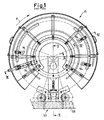
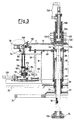
- the machine 11 has a carousel-type structure and comprises a swiveling support constituted by a shaft 12 whose one extremity 12a is inserted into a support 14, while its opposite extremity 12b is firmly attached to a plate 16.
- the shaft 12 is surrounded by a splashguard 17 to protect the shaft 12, thus preventing any damage by the fluids used to rinse the containers.
- the shaft 12 On one of its portions next to the extremity 12a, the shaft 12 exhibits a longitudinal recess housing a flap 18, which is blocked in position by screws.
- the flap 18 mounts a bushing 20 whose one extremity is firmly attached to a an element profiled in the shape of a dish 22, and whose free edge carries a sprocket wheel 24 capable of actuating the shaft 12 in a rotating manner.
- the other extremity of the bushing 20 is inserted into a first extremity of a sleeve 26 with an interposed pair of bearings 28.
- This extremity of the sleeve 26 is firmly attached to an annular plate 30, which is in turn firmly attached by screws to a supporting plate 32.
- a second extremity of the sleeve 26 is equipped with a bearing 34 which includes a bushing 36 mounted to slide along the shaft 12.
- the sleeve 26 holds a further sleeve 38 which carries a bushing 40 at one of its extremities turned toward the annular plate 30.
- the other extremity of the sleeve 38 carries a bearing 42 designed to connect in a swiveling fashion to the sleeve 38, by a thickened portion 44 of the shaft 12.
- the same extremity of the sleeve 38 carries a ring 4.6 around its outer perimeter, which is firmly attached by screws to an annular plate 48.
- the outer edge of the plate 48 is surrounded by eight columns 50, which are at their lower ends attached to a ring 52.
- the ring 52 is attached to some spoke-like beams 54 and near five of the eight columns 50, while the other columns 50 are facing a unit 56 designed to load and unload the containers to be rinsed from a conveyor 58.
- the beams 54 support, on blocks 60, a washing tank 62 designed to hold the rinsing liquid, which drops to the bottom of the machine 11 by gravity, whenever the containers are being rinsed.
- the washing tank 62 is further equipped with a discharge tube 63.
- the ring 52 and each of the beams 54 are also firmly attached to some profiled pieces 64, which carry at one of their free upper extremities some supports 66 of a guide 68.
- Each profiled piece 64 also attaches to a stiffening rib 70 and a box 72, inside which the container may be manipulated and rinsed.
- the guide 68 is constituted by a profiled ring extending along the entire length of machine 11 and engaging with some forks 74, each of which is firmly attached to a clamp 76 designed to grasp the containers. Each of the clamps 76 is supported by a fork 78 attached to the plate 16.
- Each clamp 76 faces a rinsing unit for the containers.
- the rinsing unit comprises a column 80 attached to each of the forks 78.
- a ring 82 is in turn suspended from these forks so as to run all around the perimeter of the machine 11, and is equipped with two fittings 84 facing each clamp 76 and carrying a suspended tube 86.
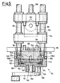
- the tubes 86 support at their lower ends a second ring 88 similar to the ring 82, and are connected to a distribution valve 90, so as to feed the fluids, liquid or inert gas, by which the containers are to be rinsed.
- the distribution valve 90 is fitted with a control lever 92, which is actuated in a rotating manner by some cams 94 of the machine 11.
- the cams 94 are provided in a number of four, three of which are supported by curved guides 96.
- Each valve 90 carries two exit fittings 98, each of which is connected to a flexible tube 100, for example made of silicon plastic.
- Each of the two flexible tubes 100 connects at its opposite end to a fitting 102 of a trolley 104, which supports an injector 106.
- the injector 106 is composed of two concentric tubes identifying two ducts, one of which is fed by one of the two flexible tubes 100, while the other duct is fed by the other flexible tube 100.
- the trolley 104 slides on the tubes 86 while being controlled by a projecting pin 108 which mounts a swiveling wheel 110.
- the wheel 110 is inserted between the free ends of a guide 112 running along the machine 11.
- This guide 112 is profiled in a C-shape and supported on platelets and collars 114 by the columns 50.
- Each fitting 84 holds a flexible tubing 116 connected to a tube 118 bent toward the center of the machine 11.
- Each tube 118 is in turn connected by flexible tubes 120 with one of two distribution chambers 122, 124.
- the distribution chambers 122, 124 are formed by a cylindrical body 126 fitted with a partition 127.
- One extremity of the body 126 is flanged and attached to the plate 16, while the opposite extremity holds two concentric tubes, each of which opens up onto one of the chambers 122, 124 and has a free extremity equipped with a threaded fitting 128.
- valves 90 are actuated by cams 94.
- a first cam 94 which is first contacted by the valves 90 after the corresponding clamp 76 has grasped a container, is mounted on the extremity of a pneumatic cylinder 129.
- the cylinder 129 can be operated so as to pass the valve 90 without starting the rinsing treatment, whenever a sensor, of a known art and not shown here for simplicity, detects that the corresponding clamp 76 has failed to pick up a container.
- the other three cams 94 are on the other hand mounted on a detachable manner on the guides 96, so as to allow their adjustment.
- the machine 11 is also fitted with additional cams 130 attached to the plate 48, which control the opening and/or closing action of the clamps 76.
- the valves 90 are of a type made of ceramic discs.
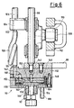
- Each valve 90 comprises a body 132 equipped with two fittings 134 connecting to the two tubes 86, one of which feeds a liquid and the other feeds an inert gas.
- Each of the fittings 134 starts a duct connected to an inlet chamber 136a, 136b which are in turn opening up to the wall opposite to that holding the fittings 134.
- Each of these ducts also has a portion which opens up toward the outside in a lateral position with respect to the body 132, and can be closed by a threaded screw 138.
- the body 132 also carries two fittings 98.
- One of the two fittings 98 is connected to a central exit chamber 140, while the other is connected to an additional exit chamber 142.
- the chambers 140 and 142 open up onto the same wall on which the chambers 136a and 136b open.
- the wall of the body 132 onto which the chambers 136a, 136b, 140 and 142 are opened, carries a firmly attached lid 144 holding three superimposed discs.
- One fixed disc 146 is firmly attached to the body 132 by pins 148 which are inserted into its recesses and face some blind holes of the same body 132.
- the disc 146 is fitted with four through holes, two of which 149 are lined up with the chambers 136a, 136b, while a central hole 150 is lined up with the chamber 140, and one hole 152 is lined up with the chamber 142. As shown in Figure 7, the hole 152 is profiled with one cylindrical portion turned toward the cylindrical body 132, and another portion turned to the opposite side and extended in a radial direction so as to form a channel.
- the stationary disc 146 is associated with a mobile disc 154, which is capable of rotating with respect to the stationary disc 146 actuated by the control lever 92.
- the disc 154 is fitted with three blind channels so as to form three additional chambers 156, 158 and 160, in which a fluid, either liquid or gaseous, accumulates so as to pass one of the holes 149 facing the fluid inlet in the valve 90, at one of the holes 150, 152 of the disc 146 corresponding to the outlets of the fluid from the valve 90, as a result of the rotating motions of the mobile disc 154.
- the mobile disc 154 is connected to an additional disc 162, which carries some pins 164 connected to the mobile disc 154 and attached to the extremity of a shaft 166 which is supported on bearings by the lid 144 and exits from the same lid 144 by a portion leading up to the control lever 92.
- the lid 144 also holds a pin 168 to act as a stop of the valve 90.
- the height of the machine 11 can be varied, so as to be adapted to the height of the various containers or bottles to be rinsed in successive treatments. This is done by sliding the sleeve 38 over the sleeve 26, while using a control known by itself and not shown here for simplicity.
- the containers which are usually formed by bottles, are moved by the conveyor 58 to the loading and unloading assembly 56 of the carousel-type rinsing machine 11, which rotates as shown by the arrows F.
- the clamps 76 operated by the cams 130 grasp the containers and cause them to rotate, so as to arrange them with their openings turned toward the bottom, under the control of the fork 74 and guide 68.
- the machine described above embodies a rinsing system based on using two fluids and providing a first treatment with a liquid and a subsequent treatment with an inert gas.
- the liquid and the gas each enter from one of the fittings 128 and accumulate in the distribution chambers 122 and 124.
- the liquid and gas are both flowing through the tubes 116, 118 and 120, respectively, entering the distribution valve 90 through the tube 86, and filling the chambers 136a and 136b, respectively, and the hole 149 aligned with the latter.
- the valve 90 selects which of the liquid or gas must be conveyed to the outlet under the control of the cams 94.
- the liquid or gas selected by the valve 90 reaches the corresponding exit fitting 98 and moves up to the injector 106, after passing the flexible tube 100.
- the injector 106 may slide from a resting position in which its supporting trolley 104 occupies a position below the tube 86 to an operating position in which the trolley 104 occupies a position above the same tube 86, so that the injector can at least partially enter the container.
- the motion of the trolley 104 which allows for the passing of the injector 106 from a resting to an operating position and vice versa, is controlled by the guide 112, through the wheel 110 and the pin 108.
- the injected liquid drops into the washing tank 62 by gravity, and may thence be removed by the discharge tube 63.
- the distribution valves 90 are controlled by the four cams 94.
- each of the cams 94 may be changed so as to vary the rinsing process, for example by lengthening or shortening the treating phases with the liquid or gas.
- FIG 8 shows the configuration of the valve 90 in the stretch of the machine 11 facing the loading and unloading unit indicated with 56 in Fig. 2. As seen, in this stretch, both holes indicated with 149 in Fig. 7 are closed and therefore no liquid or gas can cross the exit fittings 98 of the valve 90.
- Figure 9 shows the configuration assumed by the valve 90 in the stretch between the first cam 94 mounted on the pneumatic cylinder indicated with 129 in Fig. 3 and the second cam 94.
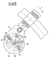
- Figure 10 shows the configuration assumed by the valve 90 in the stretch between the second and the third cam 94.
- the figure 11 finally shows the configuration assumed by the valve 90 in the stretch comprised between the third and the fourth cam 94.
- the liquid is trapped between the chamber 136a and the corresponding hole 149 closed off by the mobile disc 154.
- the gas moves from the chamber 135b and the corresponding hole 149 across the chamber 156, enters the central hole 150 to pass into the chamber 140, and exits from the valve 90 across the corresponding fitting 98.
- the rinsing machine according to this invention is essentially similar to that just described, but is capable of implementing a rinsing process which envisions three successive treatments with liquid and/or inert gas.
- Such a process usually consists of a first liquid treatment, a second liquid or inert gas treatment, and a third inert gas treatment.
- the rinsing machine in this embodiment remains essentially the same as previously described and differs from it only because of the presence of a third inlet fitting to the machine, in addition to the already available fittings 128.
- This third fitting allows conveying said fluid, either liquid or gaseous across the tubes 120, 118, 116, 86 and up to the valves 90.
- the latter have a construction and operation similar to those already described; one of these valves is shown in Figure 12, for purely exemplifying and non limiting purposes.
- valves have three inlet fittings, of the type of the two fittings indicated with 134 in Fig. 12, one for each of the various fluids, but only two exit fittings 98.
- valve with three inlet and two outlet fittings as well of the machine mounting it is essentially similar to that described above, and its description is therefore omitted for brevity.
- the machine built according to this invention embodies a rinsing process with liquids and gases which are kept separate up to the moment of injecting them into the container. This prevents a mutual contamination of the liquids and gases.
Landscapes
- Engineering & Computer Science (AREA)
- Mechanical Engineering (AREA)
- Cleaning By Liquid Or Steam (AREA)
- Cleaning In General (AREA)
- Filling Of Jars Or Cans And Processes For Cleaning And Sealing Jars (AREA)
- Manufacturing Of Printed Wiring (AREA)
- Threshing Machine Elements (AREA)
- Massaging Devices (AREA)
- Investigating Or Analysing Biological Materials (AREA)
Claims (10)
- Vorrichtung (11) zur Mehrfachbehandlung und zum automatischen Spülen mit zumindest einem Schwenkträger (12, 16), der eine Vielzahl fest angebrachter Klemmen (76) trägt, von denen jede einen Behälter ergreifen kann, wobei jede der Klemmen (76) zu einer jeweiligen Spüleinheit (86, 90, 104) weist, die durch zumindest zwei Fluide gespeist und mit zumindest einer Einspritzeinrichtung (106) ausgestattet ist, die alternativ eines der beiden Fluide in den Behälter einspritzen kann, wobei jede Spüleinheit (86, 90, 104) auch zumindest ein Verteilungsventil (90) von Scheibentyp umfasst, das eines aus zumindest zwei der Fluiden wählen kann, um so das Fluid in den Behälter durch Steuern des Starts und des Endes des Einspritzvorgangs der Fluide einzuspritzen,
dadurch gekennzeichnet, dass das Verteilungsventil (90) mit der Einspritzeinrichtung (106) durch zumindest einen flexiblen Schlauch (100) verbunden ist, wobei die Einspritzeinrichtung (106) von zumindest einer Verfahreinrichtung (104) getragen wird, die entlang zumindest eines Schlauchs (86) verschoben wird, so dass die Einspritzeinrichtung (106), während sie durch zumindest eine Führung (112) gesteuert wird, von einer Ruhestellung, in der sie nach unten zeigt, zu einer Betriebsstellung, in der sie nach oben zeigt, und umgekehrt gleiten kann. - Spülvorrichtung (11) nach Anspruch 1,
dadurch gekennzeichnet, dass der Schwenkträger (12, 16) durch zumindest eine Welle (12) ausgebildet ist, die eine erste Extremität (12a), die mit zumindest einem Träger (14) verbunden ist, und eine zweite Extremität (12b) umfasst, die der ersten Extremität (12a) gegenüberliegt und fest an einer Platte (16) der Vorrichtung (11) befestigt ist. - Spülvorrichtung (11) nach Anspruch 1
dadurch gekennzeichnet, dass das Verteilungsventil (90) durch Nocken (94) betätigt wird, wobei die Nocken (94) fest an der Vorrichtung (11) befestigt sind. - Spülvorrichtung (11) nach Anspruch 3,
dadurch gekennzeichnet, dass eine Vielzahl der Nocken (94) vorgesehen ist, so dass eine erste Nocke, die die erste Nocke darstellt, auf die das Verteilungsventil (90) trifft, nachdem eine entsprechende Klemme (76) einen Behälter ergriffen hat, an der Extremität eines pneumatischen Zylinders (129) befestigt ist, während zumindest drei zweite Nocken an Führungen (96) befestigt sind, wobei die zweiten Nocken so einstellbar sind, dass die Dauer der Sprühphasen der Spülvorrichtung (11) variiert wird. - Spülvorrichtung (11) nach Anspruch 1,
dadurch gekennzeichnet, dass das Verteilungsventil (90) vom Scheibentyp eine Vielzahl von Keramikscheiben umfasst. - Spülvorrichtung (11) nach Anspruch 1,
dadurch gekennzeichnet, dass das Verteilungsventil (90) einen Hauptkörper (132) umfasst, der durch einen Deckel (144) geschlossen ist, der mit zumindest einem Stift (168) ausgestattet ist, der als ein Anschlag für das Ventil (90) dient, wobei der Hauptkörper (132) mit zumindest einem Einlassanschlussstück (134) ausgestattet ist, das sich zu einer Einlasskammer (136a, 136b) innerhalb des Ventils (90) öffnet, wobei das Verteilungsventil (90) auch zumindest ein Auslassanschlussstück (98) umfasst, das sich zu einer Auslasskammer (140, 142) innerhalb des Ventils (90) öffnet, wobei der Hauptkörper (132) auch mit zumindest einer mobilen Scheibe (154) in Verbindung steht, die mit geformten Kammern (156, 158, 160) ausgestattet ist, die so ausgebildet sind, dass sie zumindest eine der Einlasskammern (136a, 136b) alternativ mit zumindest einer der Auslasskammern (140, 142) verbinden, um so ein Fluid zur Beförderung an die Einspritzeinrichtung (106) zu wählen. - Spülvorrichtung (11) nach Anspruch 6,
dadurch gekennzeichnet, dass das Verteilungsventil (90) zumindest eine stationäre Scheibe (146) umfasst, die zwischen dem Hauptkörper (132) und der mobilen Scheibe (154) angeordnet ist, wobei die stationäre Scheibe (146) fest an dem Körper (132) angebracht ist und einen ersten Satz von Durchgangslöchern (149) aufweist, die mit den Einlasskammern (136a, 136b) ausgerichtet sind, und einen zweiten Satz von Durchgangslöchern (150, 152) umfasst, die mit den Auslasskammern (140, 142) des Hauptkörpers (132) ausgerichtet sind. - Spülvorrichtung (11) nach Anspruch 7,
dadurch gekennzeichnet, dass zumindest ein Loch des zweiten Satzes von Durchgangslöchern (152) einen ersten zylindrischen Abschnitt umfasst, der zu dem Hauptkörper (132) gedreht ist, und einen zweiten Abschnitt umfasst, der zu der entgegengesetzten Seite bezüglich des Hauptkörpers (132) gedreht ist und sich in einer radialen Richtung erstreckt, um so einen Kanal zu bilden. - Spülvorrichtung (11) nach Anspruch 7,
dadurch gekennzeichnet, dass die mobile Scheibe (154) mit einer Vielzahl blinder Kanäle ausgestattet ist, die die geformten Kammern (156, 158, 160) bilden, wobei die mobile Scheibe (154) rotieren kann, um die geformten Kammern (156, 158, 160) zyklisch in Verbindung mit den ersten und zweiten Sätzen von Durchgangslöchern (149, 150, 152) der stationären Scheibe (146) zu bringen. - Spülvorrichtung (11) nach Anspruch 6,
dadurch gekennzeichnet, dass die mobile Scheibe (154) mit einer Anschlussscheibe (162) verbunden ist, die an der Extremität einer Welle (166) befestigt ist, die von dem Deckel (144) mit einem Abschnitt austritt, der einen Steuerhebel (92) zur Betätigung des Verteilungsventils (90) trägt.
Applications Claiming Priority (3)
| Application Number | Priority Date | Filing Date | Title |
|---|---|---|---|
| IT1999MI001708A IT1313312B1 (it) | 1999-07-30 | 1999-07-30 | Macchina sciacquatrice automatica a trattamenti multipli. |
| ITMI991708 | 1999-07-30 | ||
| PCT/EP2000/007299 WO2001008822A1 (en) | 1999-07-30 | 2000-07-28 | Multiple treating and automatically rinsing machine |
Publications (2)
| Publication Number | Publication Date |
|---|---|
| EP1200207A1 EP1200207A1 (de) | 2002-05-02 |
| EP1200207B1 true EP1200207B1 (de) | 2005-03-09 |
Family
ID=11383460
Family Applications (1)
| Application Number | Title | Priority Date | Filing Date |
|---|---|---|---|
| EP00956341A Expired - Lifetime EP1200207B1 (de) | 1999-07-30 | 2000-07-28 | Maschine zur mehrfachbehandlung und automatischer spülung |
Country Status (7)
| Country | Link |
|---|---|
| EP (1) | EP1200207B1 (de) |
| AT (1) | ATE290440T1 (de) |
| AU (1) | AU774166B2 (de) |
| DE (1) | DE60018572T2 (de) |
| ES (1) | ES2238304T3 (de) |
| IT (1) | IT1313312B1 (de) |
| WO (1) | WO2001008822A1 (de) |
Families Citing this family (3)
| Publication number | Priority date | Publication date | Assignee | Title |
|---|---|---|---|---|
| CN104959356B (zh) * | 2015-06-23 | 2017-02-01 | 杨红丽 | 一种酒瓶清洗装置 |
| IT201900007866A1 (it) * | 2019-06-03 | 2020-12-03 | Gd Spa | Macchina lavatrice per contenitori, in particolare per prodotti del settore farmaceutico |
| FR3122587B1 (fr) * | 2021-05-07 | 2025-12-26 | Sa Des Eaux Minerales D’Evian Et En Abrege S A E M E | Machine de nettoyage d’enveloppes par soufflage |
Family Cites Families (3)
| Publication number | Priority date | Publication date | Assignee | Title |
|---|---|---|---|---|
| US3568690A (en) * | 1968-10-09 | 1971-03-09 | Rudolph N Price | Washing machine and valve therefor |
| IT1259122B (it) * | 1992-06-30 | 1996-03-11 | Macchina sciacquatrice rotativa provvista di dispositivo di controllo e di distribuzione di prodotti per il trattamento di bottiglie, vasi o similari | |
| DE29803902U1 (de) * | 1998-03-05 | 1998-05-20 | KHS Maschinen- und Anlagenbau AG, 44143 Dortmund | Vorrichtung zur Überkopf-Behandlung von Flaschen |
-
1999
- 1999-07-30 IT IT1999MI001708A patent/IT1313312B1/it active
-
2000
- 2000-07-28 EP EP00956341A patent/EP1200207B1/de not_active Expired - Lifetime
- 2000-07-28 ES ES00956341T patent/ES2238304T3/es not_active Expired - Lifetime
- 2000-07-28 AT AT00956341T patent/ATE290440T1/de not_active IP Right Cessation
- 2000-07-28 DE DE60018572T patent/DE60018572T2/de not_active Expired - Fee Related
- 2000-07-28 WO PCT/EP2000/007299 patent/WO2001008822A1/en not_active Ceased
- 2000-07-28 AU AU68325/00A patent/AU774166B2/en not_active Ceased
Also Published As
| Publication number | Publication date |
|---|---|
| ITMI991708A1 (it) | 2001-01-30 |
| ATE290440T1 (de) | 2005-03-15 |
| IT1313312B1 (it) | 2002-07-17 |
| ITMI991708A0 (it) | 1999-07-30 |
| AU774166B2 (en) | 2004-06-17 |
| AU6832500A (en) | 2001-02-19 |
| EP1200207A1 (de) | 2002-05-02 |
| ES2238304T3 (es) | 2005-09-01 |
| DE60018572D1 (de) | 2005-04-14 |
| DE60018572T2 (de) | 2006-04-13 |
| WO2001008822A1 (en) | 2001-02-08 |
Similar Documents
| Publication | Publication Date | Title |
|---|---|---|
| US6079460A (en) | Rotary filling machine for filling containers with liquids | |
| JP3746820B2 (ja) | 容器洗浄機 | |
| EP1908726B1 (de) | Isobare Rotationsfüllmaschine zur Füllung von Containern mit Flüssigkeiten | |
| US6026867A (en) | Rotary filling machine | |
| CN1891614B (zh) | 利用无菌瓶盖来封闭瓶子的方法和机器 | |
| US5439655A (en) | Apparatus for washing and sterilizing rubber plugs or the like which may be used in pharmaceutical containers | |
| EP1187788A1 (de) | Abfüllvorrichtung für flaschen | |
| KR100436344B1 (ko) | 용기 처리 기계 | |
| CA1301022C (en) | Valve and feed for sterile fluids | |
| KR20000052642A (ko) | 포장용기를 살균하고 충진하는 방법과 장치 | |
| JP2017124156A (ja) | 容器クロージャを滅菌するための装置および方法 | |
| JP3462857B2 (ja) | 改良された洗浄手段を含む充填装置 | |
| AU774166B2 (en) | Multiple treating and automatically rinsing machine | |
| EP3009201A1 (de) | Waschvorrichtung, insbesondere zur thermischen desinfektion | |
| JP3569230B2 (ja) | 下方にずれたバルブをそれぞれが含む充填ヘッドを備えた充填装置 | |
| KR102064715B1 (ko) | 자동 생수 충진 시스템 | |
| EP1642656B1 (de) | Rotationsspülvorrichtung | |
| GB2188309A (en) | A bottle washing-sterilizing apparatus | |
| JPH11277017A (ja) | ロータリ式洗びん機のロータリバルブ押圧装置およびロータリバルブ洗浄装置 | |
| GB2139201A (en) | Method and apparatus for cleaning vessel-filling machines | |
| EP4212187A1 (de) | Gefässsterilisator | |
| EP1485517A1 (de) | System zum chargenweisen vakuummetallisieren von gegenständen | |
| JPH09155313A (ja) | 回転式容器洗浄装置及び方法 | |
| IT9002924A1 (it) | Perfezionamenti a macchine per la preparazione ed il riempimento di fusti per prodotti fluidi | |
| JPH11277016A (ja) | ロータリバルブの支持構造 |
Legal Events
| Date | Code | Title | Description |
|---|---|---|---|
| PUAI | Public reference made under article 153(3) epc to a published international application that has entered the european phase |
Free format text: ORIGINAL CODE: 0009012 |
|
| 17P | Request for examination filed |
Effective date: 20020121 |
|
| AK | Designated contracting states |
Kind code of ref document: A1 Designated state(s): AT BE CH CY DE DK ES FI FR GB GR IE IT LI LU MC NL |
|
| AX | Request for extension of the european patent |
Free format text: AL;LT;LV;MK;RO;SI |
|
| 17Q | First examination report despatched |
Effective date: 20040220 |
|
| GRAP | Despatch of communication of intention to grant a patent |
Free format text: ORIGINAL CODE: EPIDOSNIGR1 |
|
| GRAS | Grant fee paid |
Free format text: ORIGINAL CODE: EPIDOSNIGR3 |
|
| RAP1 | Party data changed (applicant data changed or rights of an application transferred) |
Owner name: GRUPPO BERTOLASO S.P.A. |
|
| GRAA | (expected) grant |
Free format text: ORIGINAL CODE: 0009210 |
|
| AK | Designated contracting states |
Kind code of ref document: B1 Designated state(s): AT BE CH CY DE DK ES FI FR GB GR IE IT LI LU MC NL PT SE |
|
| PG25 | Lapsed in a contracting state [announced via postgrant information from national office to epo] |
Ref country code: LI Free format text: LAPSE BECAUSE OF FAILURE TO SUBMIT A TRANSLATION OF THE DESCRIPTION OR TO PAY THE FEE WITHIN THE PRESCRIBED TIME-LIMIT Effective date: 20050309 Ref country code: FI Free format text: LAPSE BECAUSE OF FAILURE TO SUBMIT A TRANSLATION OF THE DESCRIPTION OR TO PAY THE FEE WITHIN THE PRESCRIBED TIME-LIMIT Effective date: 20050309 Ref country code: BE Free format text: LAPSE BECAUSE OF FAILURE TO SUBMIT A TRANSLATION OF THE DESCRIPTION OR TO PAY THE FEE WITHIN THE PRESCRIBED TIME-LIMIT Effective date: 20050309 Ref country code: CH Free format text: LAPSE BECAUSE OF FAILURE TO SUBMIT A TRANSLATION OF THE DESCRIPTION OR TO PAY THE FEE WITHIN THE PRESCRIBED TIME-LIMIT Effective date: 20050309 Ref country code: NL Free format text: LAPSE BECAUSE OF FAILURE TO SUBMIT A TRANSLATION OF THE DESCRIPTION OR TO PAY THE FEE WITHIN THE PRESCRIBED TIME-LIMIT Effective date: 20050309 Ref country code: AT Free format text: LAPSE BECAUSE OF FAILURE TO SUBMIT A TRANSLATION OF THE DESCRIPTION OR TO PAY THE FEE WITHIN THE PRESCRIBED TIME-LIMIT Effective date: 20050309 |
|
| RBV | Designated contracting states (corrected) |
Designated state(s): AT BE CH CY DE DK ES FI FR GB GR IE IT LI LU MC NL PT SE |
|
| REG | Reference to a national code |
Ref country code: GB Ref legal event code: FG4D |
|
| REG | Reference to a national code |
Ref country code: CH Ref legal event code: EP |
|
| REG | Reference to a national code |
Ref country code: IE Ref legal event code: FG4D |
|
| REF | Corresponds to: |
Ref document number: 60018572 Country of ref document: DE Date of ref document: 20050414 Kind code of ref document: P |
|
| PG25 | Lapsed in a contracting state [announced via postgrant information from national office to epo] |
Ref country code: GR Free format text: LAPSE BECAUSE OF FAILURE TO SUBMIT A TRANSLATION OF THE DESCRIPTION OR TO PAY THE FEE WITHIN THE PRESCRIBED TIME-LIMIT Effective date: 20050609 Ref country code: DK Free format text: LAPSE BECAUSE OF FAILURE TO SUBMIT A TRANSLATION OF THE DESCRIPTION OR TO PAY THE FEE WITHIN THE PRESCRIBED TIME-LIMIT Effective date: 20050609 |
|
| PG25 | Lapsed in a contracting state [announced via postgrant information from national office to epo] |
Ref country code: LU Free format text: LAPSE BECAUSE OF NON-PAYMENT OF DUE FEES Effective date: 20050728 Ref country code: CY Free format text: LAPSE BECAUSE OF FAILURE TO SUBMIT A TRANSLATION OF THE DESCRIPTION OR TO PAY THE FEE WITHIN THE PRESCRIBED TIME-LIMIT Effective date: 20050728 Ref country code: IE Free format text: LAPSE BECAUSE OF NON-PAYMENT OF DUE FEES Effective date: 20050728 Ref country code: GB Free format text: LAPSE BECAUSE OF NON-PAYMENT OF DUE FEES Effective date: 20050728 |
|
| PG25 | Lapsed in a contracting state [announced via postgrant information from national office to epo] |
Ref country code: MC Free format text: LAPSE BECAUSE OF NON-PAYMENT OF DUE FEES Effective date: 20050731 |
|
| NLV1 | Nl: lapsed or annulled due to failure to fulfill the requirements of art. 29p and 29m of the patents act | ||
| REG | Reference to a national code |
Ref country code: ES Ref legal event code: FG2A Ref document number: 2238304 Country of ref document: ES Kind code of ref document: T3 |
|
| PG25 | Lapsed in a contracting state [announced via postgrant information from national office to epo] |
Ref country code: PT Free format text: LAPSE BECAUSE OF FAILURE TO SUBMIT A TRANSLATION OF THE DESCRIPTION OR TO PAY THE FEE WITHIN THE PRESCRIBED TIME-LIMIT Effective date: 20050907 |
|
| REG | Reference to a national code |
Ref country code: CH Ref legal event code: PL |
|
| PLBE | No opposition filed within time limit |
Free format text: ORIGINAL CODE: 0009261 |
|
| STAA | Information on the status of an ep patent application or granted ep patent |
Free format text: STATUS: NO OPPOSITION FILED WITHIN TIME LIMIT |
|
| 26N | No opposition filed |
Effective date: 20051212 |
|
| ET | Fr: translation filed | ||
| GBPC | Gb: european patent ceased through non-payment of renewal fee |
Effective date: 20050728 |
|
| REG | Reference to a national code |
Ref country code: IE Ref legal event code: MM4A |
|
| PG25 | Lapsed in a contracting state [announced via postgrant information from national office to epo] |
Ref country code: SE Free format text: LAPSE BECAUSE OF FAILURE TO SUBMIT A TRANSLATION OF THE DESCRIPTION OR TO PAY THE FEE WITHIN THE PRESCRIBED TIME-LIMIT Effective date: 20050609 |
|
| PGFP | Annual fee paid to national office [announced via postgrant information from national office to epo] |
Ref country code: ES Payment date: 20080821 Year of fee payment: 9 |
|
| PGFP | Annual fee paid to national office [announced via postgrant information from national office to epo] |
Ref country code: FR Payment date: 20080718 Year of fee payment: 9 |
|
| PGFP | Annual fee paid to national office [announced via postgrant information from national office to epo] |
Ref country code: DE Payment date: 20080924 Year of fee payment: 9 |
|
| REG | Reference to a national code |
Ref country code: FR Ref legal event code: ST Effective date: 20100331 |
|
| PG25 | Lapsed in a contracting state [announced via postgrant information from national office to epo] |
Ref country code: FR Free format text: LAPSE BECAUSE OF NON-PAYMENT OF DUE FEES Effective date: 20090731 |
|
| PG25 | Lapsed in a contracting state [announced via postgrant information from national office to epo] |
Ref country code: DE Free format text: LAPSE BECAUSE OF NON-PAYMENT OF DUE FEES Effective date: 20100202 |
|
| REG | Reference to a national code |
Ref country code: ES Ref legal event code: FD2A Effective date: 20090729 |
|
| PG25 | Lapsed in a contracting state [announced via postgrant information from national office to epo] |
Ref country code: ES Free format text: LAPSE BECAUSE OF NON-PAYMENT OF DUE FEES Effective date: 20090729 |
|
| PGFP | Annual fee paid to national office [announced via postgrant information from national office to epo] |
Ref country code: IT Payment date: 20100728 Year of fee payment: 11 |
|
| PG25 | Lapsed in a contracting state [announced via postgrant information from national office to epo] |
Ref country code: IT Free format text: LAPSE BECAUSE OF NON-PAYMENT OF DUE FEES Effective date: 20110728 |