EP1200331B1 - Systeme de deplacement de materiaux en feuille - Google Patents
Systeme de deplacement de materiaux en feuille Download PDFInfo
- Publication number
- EP1200331B1 EP1200331B1 EP00945883A EP00945883A EP1200331B1 EP 1200331 B1 EP1200331 B1 EP 1200331B1 EP 00945883 A EP00945883 A EP 00945883A EP 00945883 A EP00945883 A EP 00945883A EP 1200331 B1 EP1200331 B1 EP 1200331B1
- Authority
- EP
- European Patent Office
- Prior art keywords
- sheet material
- clamp means
- clamp
- advancing
- forming
- Prior art date
- Legal status (The legal status is an assumption and is not a legal conclusion. Google has not performed a legal analysis and makes no representation as to the accuracy of the status listed.)
- Expired - Lifetime
Links
- 239000000463 material Substances 0.000 title claims description 62
- 238000011144 upstream manufacturing Methods 0.000 claims description 8
- 238000000034 method Methods 0.000 claims description 3
- 238000003856 thermoforming Methods 0.000 description 9
- 238000007789 sealing Methods 0.000 description 6
- 238000010438 heat treatment Methods 0.000 description 5
- 230000000694 effects Effects 0.000 description 2
- 239000012530 fluid Substances 0.000 description 2
- 238000004519 manufacturing process Methods 0.000 description 2
- 230000002093 peripheral effect Effects 0.000 description 2
- 230000008878 coupling Effects 0.000 description 1
- 238000010168 coupling process Methods 0.000 description 1
- 238000005859 coupling reaction Methods 0.000 description 1
- 238000009792 diffusion process Methods 0.000 description 1
- 239000002699 waste material Substances 0.000 description 1
Images


Classifications
-
- B—PERFORMING OPERATIONS; TRANSPORTING
- B65—CONVEYING; PACKING; STORING; HANDLING THIN OR FILAMENTARY MATERIAL
- B65H—HANDLING THIN OR FILAMENTARY MATERIAL, e.g. SHEETS, WEBS, CABLES
- B65H20/00—Advancing webs
- B65H20/16—Advancing webs by web-gripping means, e.g. grippers, clips
- B65H20/18—Advancing webs by web-gripping means, e.g. grippers, clips to effect step-by-step advancement of web
Definitions
- the invention relates to method and apparatus for transferring and positioning sheet material, as well as a container manufactured from sheet material.
- Prior art comprises blow-thermoforming machines in which sheet material is unwound from a single reel, or from a pair of reels, placed side by side, and is indexed through at least one pre-heating station, at least one sealing station and at least one forming station.
- the sheet material is advanced between heating plates which increase the temperature of the sheet material substantially up to the softening temperature and prepare the sheet material to thermoforming; in the at least one sealing station sealing mould elements join together opposing strip portions of sheet material along outlines of at least one row of container preforms, so that in each container preform openings are formed through which a forming fluid is injectable; in the at least one forming station the forming fluid is injected into the container preforms through the above mentioned openings and expand the container preforms into hollows of at leat one forming mould, so that rows of preforms are turned into respective rows of containers.
- the sheet material is indexed through the above mentioned stations by a first moving clamp disposed downstream of the at least one forming station and a second moving clamp disposed upstream of the at least one pre-heating station, the first moving clamp and the second moving clamp being mechanically coupled by a set of levers to a main driving shaft of the machine.
- Termoformed containers formed by means of such machines generally bear printed regions comprising wordings and/or images (for example for advertisements or adorning) which are pre-printed on the reels and thus the sheet material has to be indexed of accurate steps, in such a way as the above-mentioned printed regions are centered with respect to the at leat one sealing mould and the at least one forming mould.
- the above mentioned sets of levers show a further disadvantage consisting in that, it is difficult to vary the indexing step of the sheet material: in effect, in order to do so, it is necessary to act on mechanical elements of the sets of levers, with a remarkable waste of time and the need for qualified and expert personel.
- blow-thermoforming machines as above illustrated allow the positioning of only one side of the containers, which strongly restricts the aesthetic pleasantness of the containers and constitutes a remarkable obstacle to the diffusion of such containers on the market.
- blow thermoforming machines are described in EP 0881063 and US 4.106.261, where one sheet material , or group of sheets, is advanced toward a forming station by driven nip rollers while a clamping mould, downstream said forming station, advances the sheet material independently from said nip rollers.
- An object of the invention is to improve the systems for positioning of sheet material in blow-thermoforming machines.
- Another object of the invention is to allow the advancing step to be adjusted in a faster and easier manner.
- a further object is to simplify adjustment of the clamp in order to adapt the advancing step of the sheet material to the printing step.
- apparatus comprising first clamp means for indexing sheet material through forming means of said sheet material, further clamp means for indexing said sheet material toward said first clamp means substantially synchronously with said first clamp means, characterized in that said first clamp means and/or said further clamp means are coupled to non-mechanical control means.
- said non-mechanical control means comprises electronic control means.
- apparatus comprising first clamp means downstream of forming means for indexing first sheet material and second sheet material joined together by said forming means, second clamp means upstream of said forming means for indexing said first sheet material toward said first clamp means substantially synchronously with said first clamp means, characterized in that, third clamp means are provided upstream of said forming means for indexing said second sheet material toward said first clamp means substantially synchronously with said first clamp means.
- printed regions can be centered on both sides of the container.
- a container comprising first and second wall means joined together along a peripheral seal and defining an internal cavity, characterized in that, regions of said wall means extend over pre-determined positions of said first and second wall means.
- a method comprising indexing sheet material through forming means of said sheet material, characterized by controlling indexing of first portions of said sheet material independently of second portions of said sheet material.
- container walls can be formed bearing printed regions.
- thermoformed containers can be manufactured having printed regions on both the first and second wall means.
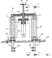
- a blow-thermoforming machine 2 comprises a reel 4 of sheet material 6 and a further reel 8 of further sheet material 10, equal or different from the sheet material 6.
- the sheet material 6, 10 is partially wound around a first idle roller 12, 12a, a tensioner roller 14, 14a moving into a curved slit 16, a second idle roller 18, 18a, third and fourth idle rollers 20, 20a, 22, 22a placed in the upper region of the machine 2.
- the sheets 6,10 descend into the front part of the machine towards preheating means 24, sealing means 26 and forming means 28, at the exit of which containers 32 are obtained from the sheet material 6,10, generally disposed along parallel rows, still joined together through non-thermoformed portions of the sheet material 6,10.
- First clamp means 30 is provided downstream of the forming means 28, comprising grasping means 34 disposed for acting on the non-thermoformed portions of the sheet material 6,10 so as to tighten thereon, or release them, the grasping means 34 being fixed to arm means 36 vertically moving as shown by arrow F into a vertical slit 38 of a front wall 40 of the machine 2.
- the arm 36 is coupled to a lead nut 42 engaged onto a screw 44 operated to rotate around its longitudinal axis by an electric motor 46 electronically controlled, for example a direct current motor with encoder.
- the first clamp means 30 can be caused to descend and lift and in particular the first clamp means 30 grasps the non-thermoformed portions of the sheet material 6,10 when these are in their upper position and release them when these are in their lower position.
- the grasp means 34 is controlled for this purpose pneumatically. This allows to index downward the sheet material 6,10 as shown by arrow F1.
- Cutting means 48 is provided downstream of the first clamp means 30 to separate the rows of containers 32 from the sheet material 6,10 and direct them to the subsequent filling and final closing unit 50.
- Second clamp means 52 is provided between the third idle rollers 20,20a and the fourth idle rollers 22,22a, to interact with the sheet material 6.
- Third clamp means 54 are provided below the second clamp means 52 to interact with the further sheet material 10.
- the second clamp means 52 and the third clamp means 54 are provided with grasping means, generally referred to as 56, similar to the grasping means 34.
- the second clamp means 52 is operated by a second electric motor 58, electronically controlled, through a second screw 60 and a second lead nut 62, while the third clamp means 54 is actuated by a third electric motor 100 electronically controlled through a third screw 98 and a third lead nut 96 , as it will be shown more in detail in the following.
- the second clamp means 52 and the third clamp means 54 are operated to reciprocate along an horizontal direction shown by arrow F3.
- the second electric motor 58 is coupled to the second screw 60 through a joint 70 and the second screw 60 is supported at its ends by walls 71,74 through respective bearings 76,78.
- the second lead nut 62 is firmly joined to a cross-bar 80 connected at its first ends to a pair of rods 72 engaged to slide along their longitudinal axis into guide bodies 82 supported, through fixing means 84, to a rear portion of the front wall 40.
- the rods 72, at their second ends are coupled to uprights 86 interconnected at their upper side by a bar 88 carrying the grasping means 56.
- the guide bodies 82 slidably receive, below the rods 72, a pair of further rods 90 that extend between a further cross-bar 91, firmly joined to the third lead nut 96 , and further vertical rods 94, between which a further bar 95 extends carrying the grasping means 56 of the third clamp means 54.
- the further cross-bar 91 is fixed to a further lead nut 96 engaged on a third screw 98 operated to rotate around its own longitudinal axis by a third electronically controlled electric motor 100.
- the first electric motor determines the advancing step of the sheet material 6,10 through pre-heating means 24, sealing means 26 and forming means 28.
- the second and third electric motor 58, 100 control the adjustment of the printing step according to a sample signal marked on edge regions of the sheet material 6,10 and detected by detector means 102,102a.
- the detector means 102,102a When the detector means 102,102a report that the mark on one or other of the strips of the sheet material 6,10 varies with respect to the theoretic position, they send a signal to the controlling means of the second and/or the third electric motor 58, 100 in order to produce a corresponding variation of its stroke along the desired direction.
- a container 32 formed by the machine 2 shows an image 104 printed on a first wall 106 so as to occupy an embossed portion 108 of the same face; the container 32 has another image 110 printed on a second wall 112 opposed to the first wall 106 so as to occupy another embossed portion 114 of the second wall 112.
- the first wall 106 is opposed to the second wall 112 so as the two faces 106 and 112 can be formed by respective parts shown with 116 and 118 respectively of a forming mould 120 comprised in the forming means 28.
- the walls 106,112 of the container 32 are joined together by a peripheral seal 130 and are concave so as to define an internal cavity 132 of the container.
- the mould parts 116 and 118 shows respective hollows 122, 124 to form the container 32 and in particular the mould parts 106, 112 are provided with recesses 126, 128 for forming the embossed parts 108, 114 of the container 32.
Landscapes
- Blow-Moulding Or Thermoforming Of Plastics Or The Like (AREA)
- Laminated Bodies (AREA)
- Containers Having Bodies Formed In One Piece (AREA)
- Making Paper Articles (AREA)
- Containers And Plastic Fillers For Packaging (AREA)
Claims (8)
- Dispositif comprenant des premiers moyens de serrage (30) pour faire avancer un matériau en feuille (6, 10) à travers des moyens de formage (24, 26, 28) dudit matériau en feuille, des moyens de serrage supplémentaires (52, 54) pour faire avancer ledit matériau en feuille (6, 10) en direction desdits premiers moyens de serrage (30) de manière sensiblement synchronisée avec lesdits premiers moyens de serrage (30), lesdits premiers moyens de serrage (30) et/ou lesdits moyens de serrage supplémentaires (52 ; 54) étant couplés à des moyens de commande non mécaniques,
caractérisé en ce que les moyens de serrage supplémentaires (52, 54) sont sélectivement déplaçables dans une direction prédéterminée (F3) correspondant à la direction de progression dudit matériau en feuille (6, 10) indépendamment des premiers moyens de serrage (30) de manière à contrôler, à l'utilisation, le degré de progression dudit matériau en feuille (6, 10) en direction desdits moyens de formage (24, 26, 28). - Dispositif selon la revendication 1, caractérisé en ce que les moyens de serrage supplémentaires sont reliés à des moyens de manoeuvre (58, 100) pour leur donner un mouvement de va-et-vient dans ladite direction prédéterminée (F3) pour faire progresser ledit matériau en feuille (6, 10) vers lesdits moyens de formage (24, 26, 28).
- Dispositif selon la revendication 2, dans lequel lesdits moyens de commande non mécaniques comprennent des moyens de commande électroniques.
- Dispositif selon l'une quelconque des revendications précédentes, dans lequel lesdits premiers moyens de serrage et/ou lesdits moyens de serrage supplémentaires (30, 52, 54) sont couplés à un moteur électrique respectif (46, 58, 100) par des moyens de contrôle de la position (42, 44, 60, 62, 80, 72, 86, 88, 98, 96, 91, 90, 94, 95).
- Dispositif selon la revendication 4, dans lequel lesdits moyens de contrôle de la position (42, 44, 60, 62, 80, 72, 86, 88, 98, 96, 91, 90, 94, 95) comprennent des moyens de vis (44, 60, 98) engagés dans des moyens d'écrou de commande respectifs (42, 62, 96) auxquels sont couplés des moyens de support (36, 72, 76, 88, 90, 94, 95) de moyens de préhension respectifs (34, 56).
- Dispositif selon l'une quelconque des revendications précédentes et comprenant de plus des moyens de préhension fixes (57) disposés en amont desdits moyens de serrage supplémentaires (52 ; 54).
- Dispositif selon la revendication 1, caractérisé en ce que les moyens de serrage supplémentaires comprennent des deuxièmes moyens de serrage (52) prévus en amont desdits moyens de formage, pour faire avancer un premier matériau en feuille (6) vers lesdits premiers moyens de serrage (30) de manière sensiblement synchronisée avec lesdits premiers moyens de serrage (30), des troisièmes moyens de serrage (54) prévus en amont desdits moyens de formage pour faire avancer un deuxième matériau en feuille (10) vers lesdits moyens de formage (24, 26, 28), de manière sensiblement synchronisée avec lesdits premiers moyens de serrage (30), lesdits premiers moyens de serrage étant disposés en aval des moyens de formage pour faire avancer ledit premier matériau en feuille et ledit deuxième matériau en feuille réunis par lesdits moyens de formage, les deuxièmes et les troisièmes moyens de serrage étant actionnés indépendamment les uns des autres.
- Procédé pour déplacer un matériau en feuille, comprenant les étapes suivantes :caractérisé en ce qu 'il comprend de plus les étapes consistant à :fourniture de premiers moyens de serrage (30), en aval de moyens de formage (24, 26, 28) d'un matériau en feuille (6, 10), fourniture de moyens de serrage supplémentaires (52, 54), en amont desdits moyens de formage (24, 26, 28),fourniture de moyens de commande non mécaniques, lesdits premiers moyens de serrage (30) et/ou lesdits moyens de serrage supplémentaires (52 ; 54) étant couplés auxdits moyens de commande non mécaniques, actionnement desdits premiers moyens de serrage (30) pour faire avancer ledit matériau en feuille (6, 10) à travers lesdits moyens de formage (24, 26, 28),déplacer sélectivement dans une direction prédéterminée (F3) correspondant à la direction de progression dudit matériau en feuille (6, 10) les moyens de serrage supplémentaires (52, 54) de manière indépendante des premiers moyens de serrage (30) pour faire progresser ledit matériau en feuille (6, 10) vers lesdits moyens de formage (24, 26, 28) ; etcommander sélectivement l'étape de progression dudit matériau en feuille (6, 10) vers lesdits moyens de formage (24, 26, 28).
Applications Claiming Priority (3)
| Application Number | Priority Date | Filing Date | Title |
|---|---|---|---|
| ITMO990146 | 1999-07-05 | ||
| IT1999MO000146A IT1310626B1 (it) | 1999-07-05 | 1999-07-05 | Sistema per movimentare materiale in foglio |
| PCT/EP2000/006340 WO2001002276A1 (fr) | 1999-07-05 | 2000-07-05 | Systeme de deplacement de materiaux en feuille |
Publications (2)
| Publication Number | Publication Date |
|---|---|
| EP1200331A1 EP1200331A1 (fr) | 2002-05-02 |
| EP1200331B1 true EP1200331B1 (fr) | 2005-06-29 |
Family
ID=11387014
Family Applications (1)
| Application Number | Title | Priority Date | Filing Date |
|---|---|---|---|
| EP00945883A Expired - Lifetime EP1200331B1 (fr) | 1999-07-05 | 2000-07-05 | Systeme de deplacement de materiaux en feuille |
Country Status (7)
| Country | Link |
|---|---|
| US (1) | US6966767B1 (fr) |
| EP (1) | EP1200331B1 (fr) |
| JP (1) | JP2004538172A (fr) |
| AU (1) | AU5982600A (fr) |
| DE (1) | DE60021080T2 (fr) |
| IT (1) | IT1310626B1 (fr) |
| WO (1) | WO2001002276A1 (fr) |
Family Cites Families (6)
| Publication number | Priority date | Publication date | Assignee | Title |
|---|---|---|---|---|
| US4106261A (en) * | 1977-08-08 | 1978-08-15 | The Dow Chemical Company | Method of forming, filling, and sealing scrim reinforced plastic bags |
| US4382762A (en) * | 1981-10-19 | 1983-05-10 | R & G Mold Company Inc. | Thermoforming apparatus and method |
| US4869048A (en) | 1987-06-29 | 1989-09-26 | Zip-Pak Incorporated | Stretcher for package forming |
| JPH02500019A (ja) | 1987-07-31 | 1990-01-11 | ロヴェル・エス・アー・エール・エル | 特に熱シール可能な材料の連続ストリップから造られた容器を製造、充填および閉鎖するための装置 |
| US5046659A (en) * | 1990-11-13 | 1991-09-10 | Mobil Oil Corporation | Latching structure for food container |
| JP3808588B2 (ja) * | 1997-05-30 | 2006-08-16 | 四国化工機株式会社 | 包装容器製造装置と包装容器製造方法 |
-
1999
- 1999-07-05 IT IT1999MO000146A patent/IT1310626B1/it active
-
2000
- 2000-07-05 DE DE60021080T patent/DE60021080T2/de not_active Expired - Fee Related
- 2000-07-05 AU AU59826/00A patent/AU5982600A/en not_active Abandoned
- 2000-07-05 EP EP00945883A patent/EP1200331B1/fr not_active Expired - Lifetime
- 2000-07-05 US US10/019,536 patent/US6966767B1/en not_active Expired - Fee Related
- 2000-07-05 JP JP2001507725A patent/JP2004538172A/ja not_active Withdrawn
- 2000-07-05 WO PCT/EP2000/006340 patent/WO2001002276A1/fr not_active Ceased
Also Published As
| Publication number | Publication date |
|---|---|
| US6966767B1 (en) | 2005-11-22 |
| EP1200331A1 (fr) | 2002-05-02 |
| AU5982600A (en) | 2001-01-22 |
| IT1310626B1 (it) | 2002-02-19 |
| DE60021080D1 (de) | 2005-08-04 |
| DE60021080T2 (de) | 2006-05-04 |
| ITMO990146A1 (it) | 2001-01-05 |
| WO2001002276A1 (fr) | 2001-01-11 |
| JP2004538172A (ja) | 2004-12-24 |
| ITMO990146A0 (it) | 1999-07-05 |
Similar Documents
| Publication | Publication Date | Title |
|---|---|---|
| JP7203163B2 (ja) | プラスチックフィルム処理を促進する方法及び装置 | |
| EP2860119B1 (fr) | Machine d'emballage par emboutissage et procédé | |
| US8376730B2 (en) | Method of clamping material and a material-clamping unit used therefor | |
| EP0744286B1 (fr) | Méthode d'application de feuilles et dispositif pour la mise en oeuvre | |
| EP3793907B1 (fr) | Procédé de commande de la position du bord de bande de produits | |
| CN109311217B (zh) | 用于拉伸和/或成形和/或施加膜元件的层压的设备和方法,以及用于层压部件的层压站和装置 | |
| CN103863600B (zh) | 热成形包装机和方法 | |
| US4743324A (en) | Printing plate mounter | |
| EP1818159B1 (fr) | Procédé pour optimiser la cadence d'une machine de thermoformage pour thermoformer des objets à partir d'une feuille thermoplastique préchauffée | |
| WO2019026316A1 (fr) | Machine d'emballage en emballage-coque | |
| JPH11321188A (ja) | モジュ―ル式自動封筒挿入機械 | |
| US3908331A (en) | Web registration method and apparatus | |
| EP3966111B1 (fr) | Machine d'emballage sans danseurs | |
| JP7459617B2 (ja) | 製袋機、製袋機の制御方法、および袋の製造方法 | |
| US5802821A (en) | Apparatus for applying a cover foil to a bottom foil including a containment structure | |
| EP1200331B1 (fr) | Systeme de deplacement de materiaux en feuille | |
| US20160158996A1 (en) | Plastic Film Stretching Apparatus | |
| CN112262078A (zh) | 包装机中展开薄膜辊 | |
| EP0490475B1 (fr) | Démarrage et arrêt d'impression des feuilles fournies | |
| JP7058384B2 (ja) | 差圧成形装置、及び、差圧成形方法 | |
| CN101195296B (zh) | 单张纸对卷筒纸的套准方法 | |
| JPH0115619Y2 (fr) | ||
| KR20110079802A (ko) | 가식 시트 및 성형 동시 가식 장치 | |
| JPH0635167B2 (ja) | 製袋機 | |
| DE10011787A1 (de) | Vorrichtung zur Herstellung von Kunststoffbehältern |
Legal Events
| Date | Code | Title | Description |
|---|---|---|---|
| PUAI | Public reference made under article 153(3) epc to a published international application that has entered the european phase |
Free format text: ORIGINAL CODE: 0009012 |
|
| 17P | Request for examination filed |
Effective date: 20020128 |
|
| AK | Designated contracting states |
Kind code of ref document: A1 Designated state(s): AT BE CH CY DE DK ES FI FR GB GR IE IT LI LU MC NL |
|
| AX | Request for extension of the european patent |
Free format text: AL;LT;LV;MK;RO;SI |
|
| 17Q | First examination report despatched |
Effective date: 20030404 |
|
| RBV | Designated contracting states (corrected) |
Designated state(s): CH DE DK FR GB IT LI |
|
| GRAP | Despatch of communication of intention to grant a patent |
Free format text: ORIGINAL CODE: EPIDOSNIGR1 |
|
| GRAS | Grant fee paid |
Free format text: ORIGINAL CODE: EPIDOSNIGR3 |
|
| GRAA | (expected) grant |
Free format text: ORIGINAL CODE: 0009210 |
|
| AK | Designated contracting states |
Kind code of ref document: B1 Designated state(s): CH DE DK FR GB IT LI |
|
| REG | Reference to a national code |
Ref country code: GB Ref legal event code: FG4D |
|
| REG | Reference to a national code |
Ref country code: CH Ref legal event code: EP |
|
| REF | Corresponds to: |
Ref document number: 60021080 Country of ref document: DE Date of ref document: 20050804 Kind code of ref document: P |
|
| PG25 | Lapsed in a contracting state [announced via postgrant information from national office to epo] |
Ref country code: DK Free format text: LAPSE BECAUSE OF FAILURE TO SUBMIT A TRANSLATION OF THE DESCRIPTION OR TO PAY THE FEE WITHIN THE PRESCRIBED TIME-LIMIT Effective date: 20050929 |
|
| REG | Reference to a national code |
Ref country code: CH Ref legal event code: NV Representative=s name: FIAMMENGHI-FIAMMENGHI |
|
| ET | Fr: translation filed | ||
| PLBE | No opposition filed within time limit |
Free format text: ORIGINAL CODE: 0009261 |
|
| STAA | Information on the status of an ep patent application or granted ep patent |
Free format text: STATUS: NO OPPOSITION FILED WITHIN TIME LIMIT |
|
| 26N | No opposition filed |
Effective date: 20060330 |
|
| PGFP | Annual fee paid to national office [announced via postgrant information from national office to epo] |
Ref country code: FR Payment date: 20060612 Year of fee payment: 7 |
|
| PGFP | Annual fee paid to national office [announced via postgrant information from national office to epo] |
Ref country code: GB Payment date: 20060613 Year of fee payment: 7 |
|
| PGFP | Annual fee paid to national office [announced via postgrant information from national office to epo] |
Ref country code: CH Payment date: 20060615 Year of fee payment: 7 |
|
| PGFP | Annual fee paid to national office [announced via postgrant information from national office to epo] |
Ref country code: DE Payment date: 20060616 Year of fee payment: 7 |
|
| PGFP | Annual fee paid to national office [announced via postgrant information from national office to epo] |
Ref country code: IT Payment date: 20060731 Year of fee payment: 7 |
|
| REG | Reference to a national code |
Ref country code: CH Ref legal event code: PL |
|
| GBPC | Gb: european patent ceased through non-payment of renewal fee |
Effective date: 20070705 |
|
| PG25 | Lapsed in a contracting state [announced via postgrant information from national office to epo] |
Ref country code: DE Free format text: LAPSE BECAUSE OF NON-PAYMENT OF DUE FEES Effective date: 20080201 Ref country code: CH Free format text: LAPSE BECAUSE OF NON-PAYMENT OF DUE FEES Effective date: 20070731 Ref country code: LI Free format text: LAPSE BECAUSE OF NON-PAYMENT OF DUE FEES Effective date: 20070731 |
|
| PG25 | Lapsed in a contracting state [announced via postgrant information from national office to epo] |
Ref country code: GB Free format text: LAPSE BECAUSE OF NON-PAYMENT OF DUE FEES Effective date: 20070705 |
|
| REG | Reference to a national code |
Ref country code: FR Ref legal event code: ST Effective date: 20080331 |
|
| PG25 | Lapsed in a contracting state [announced via postgrant information from national office to epo] |
Ref country code: FR Free format text: LAPSE BECAUSE OF NON-PAYMENT OF DUE FEES Effective date: 20070731 |
|
| PG25 | Lapsed in a contracting state [announced via postgrant information from national office to epo] |
Ref country code: IT Free format text: LAPSE BECAUSE OF NON-PAYMENT OF DUE FEES Effective date: 20070705 |