EP1201114A2 - Vorrichtung und Verfahren zum Transport und Sortieren von Blumen - Google Patents
Vorrichtung und Verfahren zum Transport und Sortieren von Blumen Download PDFInfo
- Publication number
- EP1201114A2 EP1201114A2 EP01204055A EP01204055A EP1201114A2 EP 1201114 A2 EP1201114 A2 EP 1201114A2 EP 01204055 A EP01204055 A EP 01204055A EP 01204055 A EP01204055 A EP 01204055A EP 1201114 A2 EP1201114 A2 EP 1201114A2
- Authority
- EP
- European Patent Office
- Prior art keywords
- fork
- arm
- transport
- unit
- over
- Prior art date
- Legal status (The legal status is an assumption and is not a legal conclusion. Google has not performed a legal analysis and makes no representation as to the accuracy of the status listed.)
- Granted
Links
Images

Classifications
-
- A—HUMAN NECESSITIES
- A01—AGRICULTURE; FORESTRY; ANIMAL HUSBANDRY; HUNTING; TRAPPING; FISHING
- A01G—HORTICULTURE; CULTIVATION OF VEGETABLES, FLOWERS, RICE, FRUIT, VINES, HOPS OR SEAWEED; FORESTRY; WATERING
- A01G5/00—Floral handling
-
- B—PERFORMING OPERATIONS; TRANSPORTING
- B07—SEPARATING SOLIDS FROM SOLIDS; SORTING
- B07C—POSTAL SORTING; SORTING INDIVIDUAL ARTICLES, OR BULK MATERIAL FIT TO BE SORTED PIECE-MEAL, e.g. BY PICKING
- B07C5/00—Sorting according to a characteristic or feature of the articles or material being sorted, e.g. by control effected by devices which detect or measure such characteristic or feature; Sorting by manually actuated devices, e.g. switches
- B07C5/36—Sorting apparatus characterised by the means used for distribution
Definitions
- the present invention relates to a method and apparatus for transporting and sorting flowers or other stem-shaped or elongate products, with a conveyor provided with arm-fork units which are moved along a transport path in a substantially horizontal plane.
- such a method comprises:
- Such an apparatus comprises, in particular:
- Apparatuses of that type are known from, for instance, EP449386 and EP672341.
- Both documents show a series of arm-fork units, mounted on a chain of an endless conveyor which circulates in a horizontal plane. The units are so constructed that in that plane at defined positions flowers can be hung into forks and at other well-defined positions these flowers can be delivered and can be gathered into bunches to be bundled.
- the forks are located in line with an arm extendable in a direction perpendicular to the conveyor.
- forks with arms in the form of a parallelogram construction are pivoted away from and back to the chain of the conveyor, while the forks, as in EP449386, maintain a position perpendicular to the chain.
- the flexibility is lacking in taking over and delivering fragile products such as flowers, for instance roses, because the fork, in particular the direction of the fork pins, is always fixed perpendicular to the transport direction.
- EP449386 exhibits the disadvantage that for large flowers the mutual distance between the arm-fork units in many cases proves to be too small, so that flowers get entangled with each other.
- EP672341 by contrast, has the disadvantage that although sufficient space has been created to separate the flowers from each other during transport, the use of a parallelogram construction, which defines both the intermediate distance along the conveyor as well as the perpendicular distance from the conveyor, renders this intermediate distance very large, so that the number of products that can be transported per unit length is limited considerably.
- the method according to the prior art represented above is characterized in that for assuming the delivery position the fork is rotated relative to the transport position to a delivery position.
- the apparatus according to the invention is characterized in that the arm-fork units, at the remote ends, have rotation elements to rotate the fork relative to the transport position to a rotation end angle which corresponds with the delivery position.
- This method and apparatus not only have the advantage that they are space-saving, but also that the number of rotary parts of the arm-fork unit is limited. A further considerable advantage is achieved through the basically adjustable rotation and the associated rotation end angle. These measures enable a flexible positioning of supply and discharge devices.
- the method is characterized in that the fork is rotated in the horizontal plane, while the delivery position of the fork is in line with the arm, perpendicular to the transport direction, and more in particular, the fork is rotated through an angle of at most -180° relative to the transport direction.
- a next embodiment of the method according to the present invention is characterized in that for taking over the flower the fork is rotated relative to the transport position to a take-over position, more in particular, that the fork is rotated in the horizontal plane, while in a preferred embodiment the fork is rotated through an angle of at most -180° relative to the transport direction, and in the horizontal plane the fork is brought to the take-over position while the arm-fork unit, during movement along the transport path, is moved over some distance away from the conveyor to subsequently take over the flower from the take-over position.
- the method according to the present invention is characterized in that the flowers are embraced between substantially the take-over position and the delivery position.
- the apparatus according to the present invention is characterized in that the rotation elements perform a rotation to the rotation end angle in the horizontal plane, whereby the fork, against a restraining force, is brought in line with the arm-fork unit, perpendicular to the transport direction.
- the apparatus according to the present invention is characterized in that the rotation elements in the remote end of the arm-fork unit comprise a fork with shaft-hole assembly, a rotation limiting system for limiting the rotation as far as the end angle, as well as a non-elastic drive belt, while the arm-fork unit is mounted so as to be slidable transversely to the conveyor, on a sliding block mounted on the conveyor and moving along therewith, with a vertical downwardly directed rod in the proximal end of the arm-fork unit, and a guide roller on the sliding block on one side of the unit, while the drive belt is connected by one end thereof with the lower end of the rod and extends over the guide roller and then under engaging friction around the fork shaft on the other side of the unit to the proximal end of the unit and is elastically connected therewith, more particularly, the drive belt is connected with a draw spring to the proximal end of the arm-fork unit, while as a further feature, the control elements comprise a curve
- Such an apparatus with resilient drive prevents in a suitable manner a rigid positioning of the forks. Small deviations, for instance due to curved or stiff flower stems, can be accommodated in an advantageous manner.
- the apparatus further comprises a monitoring element for monitoring the offer of new flowers to be taken over by the arm-fork unit, collected in a presenting element, and a second curve plate for bringing the arm-fork unit into a take-over position in response to a signal delivered by the monitoring element, while the flowers in a take-over position are taken over by the arm-fork unit from the presenting element, the presenting element being a fork, and more particularly the arm-fork units have a projection to lock the units in the delivery position with a catch connected with the conveyor.
- the apparatus according to the invention is further characterized in that the apparatus further comprises clamping elements for embracing the flowers to be transported, between substantially the take-over position and the delivery position, and more particularly, that the clamping elements comprise two hinging fork pins, while the fork pins are mounted in curve follower blocks for following a first clamping curve plate after taking over the flower and a second curve plate after delivering the flower.
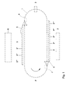
- FIG. 1 there is shown an outline diagram of an apparatus for transporting and sorting flowers or other stem-shaped or elongate products.
- a conveyor 1 circulating along an endless path takes over products from take-over positions adjacent a supply means 2, follows a transport path in the direction of arrow P and delivers products at delivery positions adjacent bunching stations 6 where the flowers can be bundled.
- Determining characteristics of the products to thereby classify the products and to be able to subsequently sort them occurs at detector 3.
- detector 3 This is, for instance, a detector for determining the length of the flowers, or for determining the color of the flowers.
- the signals obtained with the detector or detectors are processed in a processing unit (not shown), in which selection signals are obtained which actuate control elements 4, such as, for instance, a first switch, as a result of which arm-fork units, intended to transport flowers and to be discussed hereinafter with reference to Figs. 2, 3 and 4, are passed along a first curve plate 5, with repetitive delivery stations 5', 5", 5"', 5"", where the flowers are delivered in well-defined delivery positions.
- a second switch 7 is controlled adjacent the supply means 2, so that the arm-fork units are passed along a second curve plate 8, with repetitive take-over stations 8', 8", 8''', 8''', where the flowers are taken over at well-defined positions.
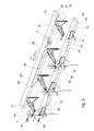
- Fig. 2 shows in an isometric view a part of the apparatus of the invention when delivering the flowers to a bunching station.
- a unit 11 is passed along a curve plate 5, whereby the unit 11, through a curve follower 13, for instance a rotatable wheel, butts against the abutting edge 51.
- a transport sector 51 with the fork 12 in a transport position a performing sector 52 where both the main arm 18 is moved away from the conveyor and the fork 12 is rotated, whereby a delivery position is assumed;
- a step sector 54 for rapidly retracting just the arm without rotation of the fork 12, so that the flower without further pushing or pulling by the fork 12 remains suspended in the delivery fork 61; a parking sector 55 which is reached after the abrupt stepped retraction; and finally a return sector 56 where both the arm 18 is retracted and the fork rotates back
- Fig. 2 shows a single plate 5 for a corresponding bunching station 6, as schematically drawn in Fig. 1.
- Fig. 1 for the different selections or sorting operations, several delivery stations 5', 5", ..., will be arranged which are equipped with similar plates 5.
- Fig. 2 It is further indicated in Fig. 2 how the roses are clamped while they are supplied to the delivery fork 61.
- Clamping elements 41 here drawn as movable pins of a fork, embrace the flowers 9. These pins can be moved apart against the force of a tension spring 46 for the purpose of delivery, or be closed again after take-over (to be discussed with reference to Fig. 3), or after delivery.
- the fork pins are mounted in curve follower blocks 42, such that when these blocks arrive at a supply means 2 (see Fig. 1) or at a bunching station 6 (see Fig. 1), they are likewise passed along a curve plate, viz.
- a second curve plate 45 at a bunching station in the same path along the transport path as the curve plate 5 drawn, while the blocks 42, with intermediate distances equal to those of the units 11, are connected with a second chain 43, which runs synchronously and parallel to the main chain 10 of the conveyor 1.
- This curve plate 45 likewise has a butting edge 70 with sectors 71, 72, 74, 75. There are shown, in succession, a transport sector 71, an opening sector 72, a delivery sector 74, and a closing sector 75, in turn followed by a second section of transport sector 71.
- a connecting block connected with the pins is moved such that the pins are moved apart, against the spring force mentioned, and remain apart until they reach the closing sector.
- Fig. 2 does not indicate that in the case of several delivery stations the curve plate does not need to be followed, a choice being allowed by a mechanical switch, viz. in Fig. 1 the first switch 4, operated and controlled with the above-mentioned selection signals.
- a mechanical switch viz. in Fig. 1 the first switch 4, operated and controlled with the above-mentioned selection signals.
- Such a switch is shown and described with reference to Fig. 3, and can be used both for a curve plate 5 and for a curve plate 45.
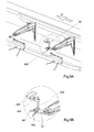
- FIG. 3 an isometric view is shown of a part of the apparatus according to the invention during take-over of the flowers at a supply means 2 as shown in Fig. 1.
- the arm-fork unit To take over the flower at that position, the arm-fork unit, while circulating along with the conveyor, must be brought into the correct position. This takeover position only needs to be assumed if a monitoring element, for instance a photocell unit, indicates that fork 40 does in fact contain a flower to be taken over. In that case, a second switch 7 is excited by a signal coming from the monitoring element, whereby the unit will proceed to follow a second curve plate 8 to end up in that position.
- a monitoring element for instance a photocell unit
- This second curve plate 8 again has a butting edge 80, and a few sectors, 81-83. There is again a transport sector 81 which the guide roller meets at some point again. If the second switch 7 is set in the takeover direction, for instance a rotary switch which is for instance electromagnetically energized, such a unit will follow a supply sector 82 which, in this exemplary embodiment, widens slightly from the first section 82' to end section 82". Along this sector, the arm 18 is extended again and the fork 12 is rotated. The widening from 82' to 82" offers the advantage that the flower will be gradually carried along from the fork 40 which is at an angle, so that damage can be avoided. In Fig.
- fork 40 has a direction, horizontal, obliquely away from the conveyor, and in the direction of transport, to thereby provide a suitable cooperation between the flower to be taken out and the fork 12 still rotating outwards to some extent.
- sector 82 follows a return sector 83, where the arm slides back and the fork rotates away again.
- Fig. 3 also shows the clamping elements 41 carried along by the second chain 43, and now represents a first curve plate 44, a butting edge 70, and sectors 70, 71, 72, 73, and 75. Contrary to Fig. 2, the sector located farthest from the conveyor is now receiving sector 73.
- the operation of the pins is the same as that on the delivery side of the apparatus. Also, opening of the pins and outward movement of the arm will be suitably synchronized again.
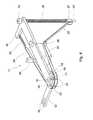
- FIG. 4 there is shown in detail an isometric view of an arm-fork unit 11.
- Main arm 18 comprises, at its end remote from the conveyor, means for rotating the fork 12 with fork pins 14.
- the rotary end of the fork 12 is, for instance, a disc 15 with shaft 16, fitting in a shaft hole 20 of the main arm.
- an end projection pin 17 which after a certain extent of rotation through a rotation end angle around a ring end 19 of the main arm 18 butts against the other side of the main arm 18 and thus, at least in this exemplary embodiment, reaches the straight position, that is, in line with the main arm 18.
- pin 17 can be adjusted to thereby obtain a different rotation end angle.
- Main arm 18 can be moved away from the conveyor 1, for instance by sliding in a sliding block 22 which is fixedly connected with the conveyor 1, for instance by means of a plate or a block (not shown in the figures). As elucidated above, such outward movement is effected via curve plates against which curve follower 13 butts.
- This curve follower is, for instance, a small wheel of a suitable material to prevent wear as much as possible.
- a drive belt 23 is connected to the main arm 18 on one side thereof via a draw spring 26, then passes around the disc 15, and on the other side of the main arm is guided over a guide roller 24, which is fixedly connected with the sliding block 22, to a slide bearing 27 fitted on a vertical rod 25, which is fixedly connected with and points downwards from the proximal end, that is, the end proximal to the conveyor 1, of the main arm.
- a compression spring 28 which is much stiffer than the draw spring 26.
- the tensions of the draw spring 26 and of the compression spring 28 are selected such that upon rotation only the draw spring 26 is extended. Such rotation roughly corresponds with the first half of the performing sector 52. Upon reaching the last section of this performing sector, the slide bearing 27 will be pulled up to some extent under an appreciably greater tension than upon the rotation. As soon as subsequently the step sector 54 is reached, the main arm, under this tension, will shoot back to the above-discussed parking sector while the fork 12 is not rotated.
- the main arm Upon reaching the most extended position, the main arm will be locked with the catch device indicated in the figure, consisting of a projection 29 on the main arm and a catch 30 fixedly connected with the above-mentioned block, or also the plate, which in turn are fixedly connected with the conveyor 1.
- the catch device indicated in the figure, consisting of a projection 29 on the main arm and a catch 30 fixedly connected with the above-mentioned block, or also the plate, which in turn are fixedly connected with the conveyor 1.
- the catch device indicated in the figure, consisting of a projection 29 on the main arm and a catch 30 fixedly connected with the above-mentioned block, or also the plate, which in turn are fixedly connected with the conveyor 1.
- the presenting element 40 comprises a fork 400 with two fork pins 401 and 402. This fork is connected through a shank 405 with a weighing element 404, which in turn is connected via a connecting piece 403 with the frame of the apparatus for transporting and sorting products, such as flowers.
Landscapes
- Life Sciences & Earth Sciences (AREA)
- Environmental Sciences (AREA)
- Sorting Of Articles (AREA)
- Discharge Of Articles From Conveyors (AREA)
Priority Applications (1)
| Application Number | Priority Date | Filing Date | Title |
|---|---|---|---|
| EP20010204055 EP1201114B1 (de) | 2000-10-25 | 2001-10-24 | Vorrichtung und Verfahren zum Transport und Sortieren von Blumen |
Applications Claiming Priority (3)
| Application Number | Priority Date | Filing Date | Title |
|---|---|---|---|
| EP00203690 | 2000-10-25 | ||
| EP00203690 | 2000-10-25 | ||
| EP20010204055 EP1201114B1 (de) | 2000-10-25 | 2001-10-24 | Vorrichtung und Verfahren zum Transport und Sortieren von Blumen |
Publications (3)
| Publication Number | Publication Date |
|---|---|
| EP1201114A2 true EP1201114A2 (de) | 2002-05-02 |
| EP1201114A3 EP1201114A3 (de) | 2004-05-26 |
| EP1201114B1 EP1201114B1 (de) | 2006-01-18 |
Family
ID=26072804
Family Applications (1)
| Application Number | Title | Priority Date | Filing Date |
|---|---|---|---|
| EP20010204055 Expired - Lifetime EP1201114B1 (de) | 2000-10-25 | 2001-10-24 | Vorrichtung und Verfahren zum Transport und Sortieren von Blumen |
Country Status (1)
| Country | Link |
|---|---|
| EP (1) | EP1201114B1 (de) |
Cited By (3)
| Publication number | Priority date | Publication date | Assignee | Title |
|---|---|---|---|---|
| EP1334654A3 (de) * | 2002-02-07 | 2004-01-21 | FPS Food Processing Systems B.V. | Blumensortiervorrichtung |
| US6834759B2 (en) | 2002-02-07 | 2004-12-28 | Fps Food Processing Systems B.V. | Flower sorter |
| NL1028644C2 (nl) * | 2005-03-29 | 2006-10-02 | Wilgengroep B V | Systeem en werkwijze voor toepassing in bijvoorbeeld een kas of warenhuis, alsmede transportinrichting. |
Family Cites Families (2)
| Publication number | Priority date | Publication date | Assignee | Title |
|---|---|---|---|---|
| US3659709A (en) * | 1970-03-23 | 1972-05-02 | Floral Grading Inc | Method and apparatus for sorting flowers |
| NL9400067A (nl) * | 1994-01-14 | 1995-08-01 | Janssen Wilhelmus H J | Inrichting voor het sorteren en bundelen van bloemen. |
-
2001
- 2001-10-24 EP EP20010204055 patent/EP1201114B1/de not_active Expired - Lifetime
Cited By (3)
| Publication number | Priority date | Publication date | Assignee | Title |
|---|---|---|---|---|
| EP1334654A3 (de) * | 2002-02-07 | 2004-01-21 | FPS Food Processing Systems B.V. | Blumensortiervorrichtung |
| US6834759B2 (en) | 2002-02-07 | 2004-12-28 | Fps Food Processing Systems B.V. | Flower sorter |
| NL1028644C2 (nl) * | 2005-03-29 | 2006-10-02 | Wilgengroep B V | Systeem en werkwijze voor toepassing in bijvoorbeeld een kas of warenhuis, alsmede transportinrichting. |
Also Published As
| Publication number | Publication date |
|---|---|
| EP1201114A3 (de) | 2004-05-26 |
| EP1201114B1 (de) | 2006-01-18 |
Similar Documents
| Publication | Publication Date | Title |
|---|---|---|
| US6688459B1 (en) | Article sorting system and method | |
| US6201203B1 (en) | Robotic containerization system | |
| US4413662A (en) | Edging system | |
| US6674037B2 (en) | Apparatus and method for transporting and sorting flowers | |
| US11866254B2 (en) | Overhead conveying system and method for determining the thickness of a hanging bag | |
| CA2045792C (en) | Material handling system | |
| US7591124B2 (en) | Automated supply system for delivery of different products to packaging mechanism | |
| US5441158A (en) | Feeding system for a garment sorter | |
| US6203262B1 (en) | Cart loading system and method for library-like materials | |
| EP0931450B1 (de) | Vorrichtung zum Sortieren und Bündeln von Blumen | |
| US20190053430A1 (en) | Apparatus for harvesting vegetable crops | |
| US5743071A (en) | Assembly for automatic packaging of series of articles or products delivered on conveyor belts | |
| EP1201114B1 (de) | Vorrichtung und Verfahren zum Transport und Sortieren von Blumen | |
| CN115959421A (zh) | 运输装置 | |
| US9415948B1 (en) | Method for stabilizing bottles for pattern forming and related device | |
| CN110612263A (zh) | 用于卷绕条带的卷绕系统和方法 | |
| NL1014057C2 (nl) | Graszodenverzamelaar. | |
| WO2004076319A1 (en) | Method and device for re-aligning items on a conveyor | |
| US5706912A (en) | Checkstand counter with dual accumulation zones | |
| CN111115171B (zh) | 一种筒子纱高效输送系统 | |
| JP6317260B2 (ja) | 個別の物体を選別する除外デバイス、アレイ、及び方法、並びにそれに応じたコンピュータ・プログラム | |
| US3628302A (en) | Bag packaging system | |
| US3393908A (en) | Leather stacker | |
| NL8101133A (nl) | Buizenpostinrichting. | |
| PL239184B1 (pl) | Zespół podający, urządzenie podające, podajnik i sposób podawania artykułów prętopodobnych |
Legal Events
| Date | Code | Title | Description |
|---|---|---|---|
| PUAI | Public reference made under article 153(3) epc to a published international application that has entered the european phase |
Free format text: ORIGINAL CODE: 0009012 |
|
| AK | Designated contracting states |
Kind code of ref document: A2 Designated state(s): AT BE CH CY DE DK ES FI FR GB GR IE IT LI LU MC NL PT SE TR |
|
| AX | Request for extension of the european patent |
Free format text: AL;LT;LV;MK;RO;SI |
|
| PUAL | Search report despatched |
Free format text: ORIGINAL CODE: 0009013 |
|
| AK | Designated contracting states |
Kind code of ref document: A3 Designated state(s): AT BE CH CY DE DK ES FI FR GB GR IE IT LI LU MC NL PT SE TR |
|
| AX | Request for extension of the european patent |
Extension state: AL LT LV MK RO SI |
|
| RIC1 | Information provided on ipc code assigned before grant |
Ipc: 7B 07C 5/36 B Ipc: 7B 07C 5/342 B Ipc: 7A 01G 5/00 A |
|
| 17P | Request for examination filed |
Effective date: 20040930 |
|
| AKX | Designation fees paid |
Designated state(s): AT BE CH CY DE DK ES FI FR GB GR IE IT LI LU MC NL PT SE TR |
|
| GRAP | Despatch of communication of intention to grant a patent |
Free format text: ORIGINAL CODE: EPIDOSNIGR1 |
|
| GRAS | Grant fee paid |
Free format text: ORIGINAL CODE: EPIDOSNIGR3 |
|
| GRAA | (expected) grant |
Free format text: ORIGINAL CODE: 0009210 |
|
| AK | Designated contracting states |
Kind code of ref document: B1 Designated state(s): AT BE CH CY DE DK ES FI FR GB GR IE IT LI LU MC NL PT SE TR |
|
| PG25 | Lapsed in a contracting state [announced via postgrant information from national office to epo] |
Ref country code: IT Free format text: LAPSE BECAUSE OF FAILURE TO SUBMIT A TRANSLATION OF THE DESCRIPTION OR TO PAY THE FEE WITHIN THE PRESCRIBED TIME-LIMIT;WARNING: LAPSES OF ITALIAN PATENTS WITH EFFECTIVE DATE BEFORE 2007 MAY HAVE OCCURRED AT ANY TIME BEFORE 2007. THE CORRECT EFFECTIVE DATE MAY BE DIFFERENT FROM THE ONE RECORDED. Effective date: 20060118 Ref country code: LI Free format text: LAPSE BECAUSE OF FAILURE TO SUBMIT A TRANSLATION OF THE DESCRIPTION OR TO PAY THE FEE WITHIN THE PRESCRIBED TIME-LIMIT Effective date: 20060118 Ref country code: BE Free format text: LAPSE BECAUSE OF FAILURE TO SUBMIT A TRANSLATION OF THE DESCRIPTION OR TO PAY THE FEE WITHIN THE PRESCRIBED TIME-LIMIT Effective date: 20060118 Ref country code: AT Free format text: LAPSE BECAUSE OF FAILURE TO SUBMIT A TRANSLATION OF THE DESCRIPTION OR TO PAY THE FEE WITHIN THE PRESCRIBED TIME-LIMIT Effective date: 20060118 Ref country code: FI Free format text: LAPSE BECAUSE OF FAILURE TO SUBMIT A TRANSLATION OF THE DESCRIPTION OR TO PAY THE FEE WITHIN THE PRESCRIBED TIME-LIMIT Effective date: 20060118 Ref country code: CH Free format text: LAPSE BECAUSE OF FAILURE TO SUBMIT A TRANSLATION OF THE DESCRIPTION OR TO PAY THE FEE WITHIN THE PRESCRIBED TIME-LIMIT Effective date: 20060118 |
|
| REG | Reference to a national code |
Ref country code: GB Ref legal event code: FG4D |
|
| REG | Reference to a national code |
Ref country code: CH Ref legal event code: EP |
|
| REG | Reference to a national code |
Ref country code: IE Ref legal event code: FG4D |
|
| REF | Corresponds to: |
Ref document number: 60116709 Country of ref document: DE Date of ref document: 20060406 Kind code of ref document: P |
|
| PG25 | Lapsed in a contracting state [announced via postgrant information from national office to epo] |
Ref country code: DK Free format text: LAPSE BECAUSE OF FAILURE TO SUBMIT A TRANSLATION OF THE DESCRIPTION OR TO PAY THE FEE WITHIN THE PRESCRIBED TIME-LIMIT Effective date: 20060418 Ref country code: SE Free format text: LAPSE BECAUSE OF FAILURE TO SUBMIT A TRANSLATION OF THE DESCRIPTION OR TO PAY THE FEE WITHIN THE PRESCRIBED TIME-LIMIT Effective date: 20060418 |
|
| PG25 | Lapsed in a contracting state [announced via postgrant information from national office to epo] |
Ref country code: DE Free format text: LAPSE BECAUSE OF FAILURE TO SUBMIT A TRANSLATION OF THE DESCRIPTION OR TO PAY THE FEE WITHIN THE PRESCRIBED TIME-LIMIT Effective date: 20060419 |
|
| PG25 | Lapsed in a contracting state [announced via postgrant information from national office to epo] |
Ref country code: ES Free format text: LAPSE BECAUSE OF FAILURE TO SUBMIT A TRANSLATION OF THE DESCRIPTION OR TO PAY THE FEE WITHIN THE PRESCRIBED TIME-LIMIT Effective date: 20060429 |
|
| PG25 | Lapsed in a contracting state [announced via postgrant information from national office to epo] |
Ref country code: PT Free format text: LAPSE BECAUSE OF FAILURE TO SUBMIT A TRANSLATION OF THE DESCRIPTION OR TO PAY THE FEE WITHIN THE PRESCRIBED TIME-LIMIT Effective date: 20060619 |
|
| REG | Reference to a national code |
Ref country code: CH Ref legal event code: PL |
|
| ET | Fr: translation filed | ||
| PG25 | Lapsed in a contracting state [announced via postgrant information from national office to epo] |
Ref country code: IE Free format text: LAPSE BECAUSE OF NON-PAYMENT OF DUE FEES Effective date: 20061024 |
|
| PG25 | Lapsed in a contracting state [announced via postgrant information from national office to epo] |
Ref country code: MC Free format text: LAPSE BECAUSE OF NON-PAYMENT OF DUE FEES Effective date: 20061031 |
|
| PLBE | No opposition filed within time limit |
Free format text: ORIGINAL CODE: 0009261 |
|
| STAA | Information on the status of an ep patent application or granted ep patent |
Free format text: STATUS: NO OPPOSITION FILED WITHIN TIME LIMIT |
|
| 26N | No opposition filed |
Effective date: 20061019 |
|
| GBPC | Gb: european patent ceased through non-payment of renewal fee |
Effective date: 20061024 |
|
| PG25 | Lapsed in a contracting state [announced via postgrant information from national office to epo] |
Ref country code: GB Free format text: LAPSE BECAUSE OF NON-PAYMENT OF DUE FEES Effective date: 20061024 |
|
| PG25 | Lapsed in a contracting state [announced via postgrant information from national office to epo] |
Ref country code: GR Free format text: LAPSE BECAUSE OF FAILURE TO SUBMIT A TRANSLATION OF THE DESCRIPTION OR TO PAY THE FEE WITHIN THE PRESCRIBED TIME-LIMIT Effective date: 20060419 |
|
| PG25 | Lapsed in a contracting state [announced via postgrant information from national office to epo] |
Ref country code: TR Free format text: LAPSE BECAUSE OF FAILURE TO SUBMIT A TRANSLATION OF THE DESCRIPTION OR TO PAY THE FEE WITHIN THE PRESCRIBED TIME-LIMIT Effective date: 20060118 Ref country code: LU Free format text: LAPSE BECAUSE OF NON-PAYMENT OF DUE FEES Effective date: 20061024 |
|
| PG25 | Lapsed in a contracting state [announced via postgrant information from national office to epo] |
Ref country code: CY Free format text: LAPSE BECAUSE OF FAILURE TO SUBMIT A TRANSLATION OF THE DESCRIPTION OR TO PAY THE FEE WITHIN THE PRESCRIBED TIME-LIMIT Effective date: 20060118 |
|
| PGFP | Annual fee paid to national office [announced via postgrant information from national office to epo] |
Ref country code: FR Payment date: 20091110 Year of fee payment: 9 Ref country code: IT Payment date: 20091023 Year of fee payment: 9 |
|
| PG25 | Lapsed in a contracting state [announced via postgrant information from national office to epo] |
Ref country code: FR Free format text: LAPSE BECAUSE OF NON-PAYMENT OF DUE FEES Effective date: 20101102 |
|
| REG | Reference to a national code |
Ref country code: FR Ref legal event code: ST Effective date: 20110630 |
|
| PG25 | Lapsed in a contracting state [announced via postgrant information from national office to epo] |
Ref country code: IT Free format text: LAPSE BECAUSE OF NON-PAYMENT OF DUE FEES Effective date: 20101024 |
|
| REG | Reference to a national code |
Ref country code: NL Ref legal event code: SD Effective date: 20121219 |
|
| PGFP | Annual fee paid to national office [announced via postgrant information from national office to epo] |
Ref country code: NL Payment date: 20200922 Year of fee payment: 20 |
|
| REG | Reference to a national code |
Ref country code: NL Ref legal event code: MK Effective date: 20211023 |