EP1201152B1 - Vorrichtung zur Schönheitsbehandlung - Google Patents
Vorrichtung zur Schönheitsbehandlung Download PDFInfo
- Publication number
- EP1201152B1 EP1201152B1 EP01125533A EP01125533A EP1201152B1 EP 1201152 B1 EP1201152 B1 EP 1201152B1 EP 01125533 A EP01125533 A EP 01125533A EP 01125533 A EP01125533 A EP 01125533A EP 1201152 B1 EP1201152 B1 EP 1201152B1
- Authority
- EP
- European Patent Office
- Prior art keywords
- steam
- mist
- liquid
- water
- beauty appliance
- Prior art date
- Legal status (The legal status is an assumption and is not a legal conclusion. Google has not performed a legal analysis and makes no representation as to the accuracy of the status listed.)
- Expired - Lifetime
Links
- 230000003796 beauty Effects 0.000 title claims abstract description 54
- 239000003595 mist Substances 0.000 claims abstract description 107
- 239000007788 liquid Substances 0.000 claims abstract description 98
- XLYOFNOQVPJJNP-UHFFFAOYSA-N water Substances O XLYOFNOQVPJJNP-UHFFFAOYSA-N 0.000 claims description 112
- 239000011148 porous material Substances 0.000 claims description 33
- 239000011358 absorbing material Substances 0.000 claims description 14
- 239000000463 material Substances 0.000 claims description 3
- 230000000694 effects Effects 0.000 description 7
- 230000009471 action Effects 0.000 description 5
- 230000001815 facial effect Effects 0.000 description 3
- 239000002245 particle Substances 0.000 description 2
- 238000005192 partition Methods 0.000 description 2
- 238000007789 sealing Methods 0.000 description 2
- 230000003750 conditioning effect Effects 0.000 description 1
- 230000001419 dependent effect Effects 0.000 description 1
- 239000003814 drug Substances 0.000 description 1
- 229920001971 elastomer Polymers 0.000 description 1
- 230000006355 external stress Effects 0.000 description 1
- -1 for example Substances 0.000 description 1
- 229920000126 latex Polymers 0.000 description 1
- 239000006210 lotion Substances 0.000 description 1
- 230000004048 modification Effects 0.000 description 1
- 238000012986 modification Methods 0.000 description 1
- 239000004745 nonwoven fabric Substances 0.000 description 1
- 230000009467 reduction Effects 0.000 description 1
- 229920005989 resin Polymers 0.000 description 1
- 239000011347 resin Substances 0.000 description 1
Images




Classifications
-
- B—PERFORMING OPERATIONS; TRANSPORTING
- B05—SPRAYING OR ATOMISING IN GENERAL; APPLYING FLUENT MATERIALS TO SURFACES, IN GENERAL
- B05B—SPRAYING APPARATUS; ATOMISING APPARATUS; NOZZLES
- B05B7/00—Spraying apparatus for discharge of liquids or other fluent materials from two or more sources, e.g. of liquid and air, of powder and gas
- B05B7/24—Spraying apparatus for discharge of liquids or other fluent materials from two or more sources, e.g. of liquid and air, of powder and gas with means, e.g. a container, for supplying liquid or other fluent material to a discharge device
- B05B7/2402—Apparatus to be carried on or by a person, e.g. by hand; Apparatus comprising containers fixed to the discharge device
- B05B7/2405—Apparatus to be carried on or by a person, e.g. by hand; Apparatus comprising containers fixed to the discharge device using an atomising fluid as carrying fluid for feeding, e.g. by suction or pressure, a carried liquid from the container to the nozzle
- B05B7/2435—Apparatus to be carried on or by a person, e.g. by hand; Apparatus comprising containers fixed to the discharge device using an atomising fluid as carrying fluid for feeding, e.g. by suction or pressure, a carried liquid from the container to the nozzle the carried liquid and the main stream of atomising fluid being brought together by parallel conduits placed one inside the other
-
- A—HUMAN NECESSITIES
- A45—HAND OR TRAVELLING ARTICLES
- A45D—HAIRDRESSING OR SHAVING EQUIPMENT; EQUIPMENT FOR COSMETICS OR COSMETIC TREATMENTS, e.g. FOR MANICURING OR PEDICURING
- A45D20/00—Hair drying devices; Accessories therefor
- A45D20/48—Hair-drying combs or hair-drying brushes, with internal heating means
- A45D20/50—Hair-drying combs or hair-drying brushes, with internal heating means and provision for an air stream
-
- A—HUMAN NECESSITIES
- A61—MEDICAL OR VETERINARY SCIENCE; HYGIENE
- A61H—PHYSICAL THERAPY APPARATUS, e.g. DEVICES FOR LOCATING OR STIMULATING REFLEX POINTS IN THE BODY; ARTIFICIAL RESPIRATION; MASSAGE; BATHING DEVICES FOR SPECIAL THERAPEUTIC OR HYGIENIC PURPOSES OR SPECIFIC PARTS OF THE BODY
- A61H33/00—Bathing devices for special therapeutic or hygienic purposes
- A61H33/06—Artificial hot-air or cold-air baths; Steam or gas baths or douches, e.g. sauna or Finnish baths
- A61H33/12—Steam baths for the face
-
- B—PERFORMING OPERATIONS; TRANSPORTING
- B05—SPRAYING OR ATOMISING IN GENERAL; APPLYING FLUENT MATERIALS TO SURFACES, IN GENERAL
- B05B—SPRAYING APPARATUS; ATOMISING APPARATUS; NOZZLES
- B05B7/00—Spraying apparatus for discharge of liquids or other fluent materials from two or more sources, e.g. of liquid and air, of powder and gas
- B05B7/24—Spraying apparatus for discharge of liquids or other fluent materials from two or more sources, e.g. of liquid and air, of powder and gas with means, e.g. a container, for supplying liquid or other fluent material to a discharge device
- B05B7/2402—Apparatus to be carried on or by a person, e.g. by hand; Apparatus comprising containers fixed to the discharge device
- B05B7/2405—Apparatus to be carried on or by a person, e.g. by hand; Apparatus comprising containers fixed to the discharge device using an atomising fluid as carrying fluid for feeding, e.g. by suction or pressure, a carried liquid from the container to the nozzle
- B05B7/2429—Apparatus to be carried on or by a person, e.g. by hand; Apparatus comprising containers fixed to the discharge device using an atomising fluid as carrying fluid for feeding, e.g. by suction or pressure, a carried liquid from the container to the nozzle the carried liquid and the main stream of atomising fluid being brought together after discharge
-
- A—HUMAN NECESSITIES
- A45—HAND OR TRAVELLING ARTICLES
- A45D—HAIRDRESSING OR SHAVING EQUIPMENT; EQUIPMENT FOR COSMETICS OR COSMETIC TREATMENTS, e.g. FOR MANICURING OR PEDICURING
- A45D1/00—Curling-tongs, i.e. tongs for use when hot; Curling-irons, i.e. irons for use when hot; Accessories therefor
- A45D2001/008—Curling-tongs, i.e. tongs for use when hot; Curling-irons, i.e. irons for use when hot; Accessories therefor with vapor generation, e.g. steam
Definitions
- the present invention relates to a beauty appliance according to the preamble of claim 1.
- FIG 11 shows a conventional hair dryer or a hair setter with a brush.
- the hair dryer 100 includes a steam water tank 102, a porous material 104 and a heater 106. Water stored in the steam water tank 102 is supplied to the heater 106 via the porous material 104. The heater 106 heats the water to generate steam.
- a beauty appliance according to the preamble of claim 1 is known from US 4 274 588 A.
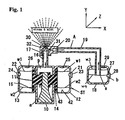
- a beauty appliance A for example, for hair styling and facial treatment, includes a steam ejection device a and a mist ejection device b.
- the beauty appliance A is, for example, a hair dryer with a brush, an apparatus for skin treatment, facial treatment, and the like.
- the steam ejection device a includes a steam generating chamber 9, a steam water tank ST and water absorbing material 11.
- the water absorbing material 11 is, for example, nonwoven fabric such as a felt, porous material such as sponge rubber, resin and the like.
- the steam generating chamber 9 contains a heater 10, for example, a PTC heater.
- the porous material 11 is provided to surround the circumferential surface of the heater 10.
- the steam water tank ST is positioned to cover the sides of the steam generating chamber 9 and is divided, for example, into a left tank 12 and a right tank 13.
- the porous material 11 extends into the tanks 12 and 13 through side-walls 14 and 15 such that a part of the porous material 11 is positioned in the tanks 12 and 13. Accordingly, the porous material 11 connects the steam generating chamber 9 and the tanks 12 and 13.
- the porous material 11 and the tanks 12 and 13 are connected so as not to form gaps between the outer circumference of the porous material 11 and the outer circumference of the tanks 12 and 13. Hence, water stored in the tanks 12 and 13 does not leak.
- the porous material 11 in the tanks 12 and 13 extends along a substantially entire height in a height direction Y direction) of the tanks 12 and 13.
- the porous material 11 in the tanks 12 and 13 extends along a substantially entire width in a width direction (Z direction) of the tanks 12 and 13 (see Fig. 2a).
- the tanks 12 and 13 have apertures 21 and 22, respectively, for supplying water.
- Detachable sealing caps 23 and 24 are provided to seal the water stored in the tanks 12 and 13.
- Pressure adjustment valves 25 and 26 are provided in the tanks 12 and 13, respectively.
- the valves 25 and 26 are configured to open when the amount of the water in the tanks 12 and 13 reduces and thus the pressure difference between the pressure in the tanks 12 and 13 and the atomospheric pressure is larger than a predetermined threshold pressure difference.
- the valves 25 and 26 are configured to close when the pressure difference is less than or equal to the predetermined threshold pressure difference.
- a steam ejection nozzle 17 is provided at an end of a passage 16.
- the mist ejection device b includes a mist liquid tank 18 and a liquid passage 19.
- the liquid passage 19 is hermetically connected to the mist liquid tank 18.
- One end of the passage 19 extends to the approximate center portion s of the mist liquid tank 18.
- Another end of the passage 19 is hermetically connected to a mist ejection nozzle 20.
- the nozzle 20 is positioned near the steam ejection nozzle 17 so that the Venturi effect may be used.
- the tank 18 has an aperture 27 for supplying water.
- a detachable sealing cap 28 is provided in the aperture 27 to seal the water stored in the tank 18.
- a pressure adjustment valve 29 is provided on an upper wall of the tank 18.
- the valve 29 is configured to open when the amount of the water in the mist liquid tank 18 reduces and thus the pressure difference between the pressure in the mist liquid tank 18 and the atomospheric pressure is larger than a predetermined threshold pressure difference. On the other hand, the valve 29 is configured to close when the pressure difference is less than or equal to the predetermined threshold pressure difference.
- Water is supplied to the tanks 12 and 13 through the apertures 21 and 22, respectively.
- the water stored in the tanks 12 and 13 is sealed by the seal caps 23 and 24, respectively.
- Water is also supplied to the mist liquid tank 18 through the aperture 27 and the water stored in the tank 18 is sealed by the seal cap 28.
- the porous material 11 absorbs the water in the tanks 12 and 13 through the capillary action.
- the water absorbed in the porous material 11 is heated by the heater 10 to generate steam in the steam generating chamber 9.
- the pressure in the steam generating chamber 9 increases as more steam is generated.
- the pressurized steam passes through the open passage 16 and is ejected through the steam ejection nozzle 17.
- the amount of the generated steam is controlled by adjusting the contacting area between the porous material 11 and the heater 10. For example, the larger the contacting area is, the more steam is generated.
- the steam pressure in the steam generating chamber 9 may be increased by increasing the amount of the generated steam.
- the ejection velocity at the ejection nozzle 17 may be increased without increasing the steam generation amount. For example, by making the cross-sectional area of a steam ejection tip 32 smaller, the steam pressure in the steam generating chamber 9 increases. Accordingly, the steam ejection velocity increases.
- the amount of the generated mist is controlled by adjusting the cross-sectional area and the length of the liquid passage 19. Also, the generation mist amount is controlled by adjusting the cross-sectional area and the length of the mist ejection tip 31 of the mist ejection nozzle 20.
- the pressure adjustment valves 25, 26 and 29 restore the pressures in the tanks 12 and 13 and the mist liquid tank 18, respectively, to the predetermined pressure. The water in the tanks 12 and 13 and the liquid in the mist liquid tank 18 reduces as time elapses.
- the initial water level w1 reduces to a water level w2 after a certain time has elapsed. Since water contacts the porous material 11 at both water levels w1 and w2 in the tanks 12 and 13, the porous material 11 keeps absorbing water by the capillary action and continuously supplies steam until the water in the tanks 12 and 13 is almost gone.
- the tip of the liquid passage 19 extends to, for example, a water level w4 in the mist liquid tank 18.
- the liquid passage 19 may draw the water in the mist liquid tank 18 to the mist ejection nozzle 20 until the level of the water in the tank 18 reduces from the initial water level w3 to the level w4.
- the tip of the liquid passage 19 is separated from the water surface and thus unable to draw water. Accordingly, a certain amount of water is left in the mist liquid tank 18 without being drawn to the liquid passage 19.
- the appliance A operates when it rotates around a certain axis at certain degrees.
- the appliance A rotates 360 degrees around the axis Y, 180 degrees around the axis X, or 180 degrees around the axis Z, the appliance A operates similarly to the appliance A which is in a position shown in Fig. 1.
- Figs. 2(a) and 2(b) show a cross-sectional view when the appliance A rotates 90 degrees around the axis X.
- the level of the water in the tanks 12 and 13 reduces from the initial level w1 to a level w2 as time passes. Since the water in the tanks 12 and 13 contacts the porous material 11 at both levels w1 and w2, the water is supplied to the porous material 11 by the capillary action regardless of the water level. Thus, steam is continuously generated until the water in the tanks 12 and 13 is almost gone.
- the mist liquid tank 18 as shown in Fig.
- the passage 19 may draw the liquid into the mist ejection nozzle 20.
- the tip of the passage 19 is separated from the liquid surface, and unable to draw the liquid. Accordingly, a certain amount of water is left in the mist liquid tank 18.
- Figs. 3(a) and 3(b) show a cross-sectional view when the appliance A rotates 90 degrees around the axis Z.
- the level of the water in the tank 12 reduces from the initial level w1 to a level w2. Since the water in the tank 12 contacts the porous material 11 at both levels w1 and w2, the water is supplied to the porous material 11 by the capillary action regardless of the water level. Thus, steam is continuously generated until the water in the tank 12 is almost gone.
- the porous material 11 is separated from the water surface and cannot absorb water. To avoid this situation, as shown in Fig.
- the porous material 11 includes, for example, an extended portion 33 which extends along the X axis (a depth direction) into the tanks 12 and 13. Accordingly, the extended portion 33 the porous material 11 is always submerged in the water.
- the mist liquid tank 18 in this embodiment operates similarly to that shown in Fig. 2(b) and thus, an explanation is omitted here.
- the beauty appliance (A) may operate regardless of the angle.
- the number of the steam water tanks (ST) is at least two. By increasing the number of the steam water tanks, more water is supplied to generate more steam.
- Fig. 5 shows the steam water tank ST which is divided into four compartments.
- the four steam compartments 34, 35, 36 and 37 are separated from each other.
- the beauty appliance A may operate efficiently regardless of its angle. More steam is generated from the four steam water tanks. The steam temperature may be lowered. Because of the four steam water tanks, moisture may be kept more efficiently while reducing the risk of burning hair or skin, for example. By adding medicine or conditioning lotions in the mist liquid tank 18, the beauty appliance A may be used for skin care or hair treatment, and the like.
- the empty mist liquid tank 18 is operated without shutting down the liquid passage 19 so that the air through the passage 19 may lower the temperature of the steam through the ejection nozzle 17.
- the pressure adjustment valve 29 is opened.
- the temperature of the steam through the steam ejection nozzle 17. is lowered when the steam mixes with air coming through the pressure adjustment valve 29.
- the mist ejection nozzle 20 draws air instead of liquid, and the temperature of the steam does not rise. Also, certain scents may be added to the mist liquid tank 18 to enhance relaxation effects.
- ejection flow of the steam in the steam ejection nozzle causes a flow of the liquid toward the mist ejection nozzle from the mist liquid tank.
- the vacuum pressure caused by the ejection flow of the steam in the steam ejection nozzle (the Venturi effect) is utilized. Accordingly, the structure of the beauty appliance A may be simplified, since no power source is necessary when supplying liquid or air to the mist ejection nozzle 20.
- steam may be ejected steadily regardless of the angle or posture of the beauty appliance A.
- FIG. 6 Another embodiment of the steam water tank ST is shown in Fig. 6.
- the porous material 11 fills tanks 12 and 13 of the steam water tank ST.
- the porous material 11 absorbs a predetermined amount of water to keep supplying water to the heater 10 while the beauty appliance A is used. Therefore, in this embodiment, the beauty appliance A may be used regardless of the angle of the beauty appliance A with respect to the X, Y or Z axes. Accordingly, the appliance A of this embodiment may be applied to, for example, a portable device such as a hair dryer with a brush.
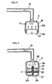
- a mist liquid tank 18 according to another embodiment of the present invention is shown in Fig. 7.
- a water retaining chamber 56 is provided in the mist liquid tank 18 and is connected hermetically to the liquid passage 19.
- the water retaining chamber 56 is made of elastically shrinkable material, for example, flexible material with low hardness such as rubber latex and the like.
- the water retaining chamber 56 has an aperture at a portion which is connected to the liquid passage 19. The amount of the liquid supplied to the chamber 56 is limited by the volume of the mist liquid tank 18. Thus, breakage of the water retaining chamber 56 due to internal and external stresses in the water retaining chamber 56 may be prevented.
- the amount of the liquid in the water retaining chamber 56 reduces as the mist ejection nozzle 20 draws the liquid from the water retaining chamber 56.
- the equivalent volume of the chamber 56 also reduces.
- the water retaining chamber 56 also functions as a volume controller.
- the nozzle 20 may be able to draw almost all of the water in the water retaining chamber 56 and the beauty appliance A may be used at any angle.
- a mist liquid tank 18 according to another embodiment of the present invention is shown in Fig. 8.
- the mist liquid tank 18 of this embodiment has an external container 58 in a cylindrical shape and an internal container 57 which is movably provided in the external container 58.
- a water storage chamber 70 is defined between the internal container 57 and the external container 58. The volume of the water storage chamber 70 changes according to the movement of the internal container 57.
- the internal container 57 is connected hermetically at the bottom circumference of the external container 58.
- the liquid passage 19 is hermetically connected to the external container 58.
- the internal container 57 moves upward to compensate the reduction in the liquid in the mist liquid tank 18. Accordingly, similar effects to the above-described embodiment may be expected and the nozzle 20 may draw most of the water in the internal container 58 and the beauty appliance A may be used at any angle.
- a mist liquid tank 18 according to another embodiment of the present invention is shown in Fig. 9.
- a partition wall 61 is provided in the mist liquid tank 18 to divide the mist liquid tank 18 into a mist generating chamber 59 and a water storage chamber 60.
- An ultrasonic vibrator 62 is provided in the mist generating chamber 59.
- the water storage chamber is configured to storage liquid, for example, water therein.
- a porous material 11 extends from the water storage chamber 60 to the mist generating chamber 59 and is configured to absorb the water.
- the ultrasonic vibrator 62 is provided to contact the porous material I I and configured to vibrate the porous material to generate mist.
- the porous material 11 heretically contacts the partition wall 61 such that water does not leak.
- the porous material 11 absorbs the water in the storage chamber 60 by the capillary action and the extended part of the porous material 11 at the ultrasonic vibrator 62 generates mist in the mist generating chamber 59.
- the mist ejection nozzle 20 draws the mist and mixes it with the steam, thereby ejecting fine steam particles with lower temperatures. Since no separate power source such as a motor driven fan is not necessary to draw the mist to the mist ejection nozzle 20, the structure of this embodiment may be simplified.
- a brush unit 64 includes a steam ejection device a and a mist ejection device b. Steam and mist are ejected from the brush unit 64. Since the ejected steam and mist directly target the hair, for example, the appliance A may be used more efficiently, and the percentage of the ejected mist stuck on the hair may become higher. The steam ejected from the beauty appliance A includes enough mist. Accordingly, hair may be treated well. Also, the beauty appliance A of this invention may be used as a device for facial treatment, for example.
Landscapes
- Health & Medical Sciences (AREA)
- Public Health (AREA)
- Life Sciences & Earth Sciences (AREA)
- Pain & Pain Management (AREA)
- Physical Education & Sports Medicine (AREA)
- Rehabilitation Therapy (AREA)
- Epidemiology (AREA)
- Animal Behavior & Ethology (AREA)
- General Health & Medical Sciences (AREA)
- Veterinary Medicine (AREA)
- Devices For Medical Bathing And Washing (AREA)
- Cleaning And Drying Hair (AREA)
- Brushes (AREA)
- Percussion Or Vibration Massage (AREA)
- Massaging Devices (AREA)
Claims (18)
- Vorrichtung zur Schönheitsbehandlung, die aufweist:eine Dampfausstoßvorrichtung (a), die einen Dampfwasserbehälter (ST), der dazu ausgelegt ist, darin Wasser zu enthalten, eine Erwärmungsvorrichtung (10), die dazu ausgelegt ist, das Wasser zu erwärmen, um Dampf zu erzeugen, und eine Dampfausstoßdüse (17) aufweist, durch welche der Dampf ausgestoßen wird; undeine Nebelausstoßvorrichtung (b), die einen Nebelflüssigkeitsbehälter (18), der dazu ausgelegt ist, darin Flüssigkeit zu enthalten, und eine Nebelausstoßdüse (20) aufweist, die derart in Beziehung zu der Dampfausstoßdüse (17) angeordnet ist, dass der Ausstoßfluss des Dampfs in der Dampfausstoßdüse (17) einen Flüssigkeitsfluss von dem Nebelflüssigkeitsbehälter (18) zu der Nebelausstoßdüse (20) bewirkt, und bewirkt, dass die Flüssigkeit als Nebel ausgestoßen wird,dadurch gekennzeichnet, dass
der Dampfwasserbehälter (ST) eine Mehrzahl von Wasserspeicherkammern beinhaltet. - Vorrichtung zur Schönheitsbehandlung nach Anspruch 1, die weiterhin eine Bürste (64) aufweist, in welcher die Dampfausstoßdüse (17) und die Nebelausstoßdüse (20) vorgesehen sind.
- Vorrichtung zur Schönheitsbehandlung nach Anspruch 1, wobei die Dampfausstoßvorrichtung (a) eine Dampferzeugungskammer (9), die mit der Dampfausstoßdüse (17) verbunden ist, und ein Wasser absorbierendes Material (11) aufweist, das sich von dem Dampfwasserbehälter (ST) zu der Dampferzeugungskammer (9) ausdehnt, wobei die Dampferzeugungskammer (9) dazu ausgelegt ist, das Wasser absorbierende Material (11) in der Dampferzeugungskammer (9) zu erwärmen, um den Dampf zu erzeugen.
- Vorrichtung zur Schönheitsbehandlung nach Anspruch 3, wobei das Wasser absorbierende Material (11) ein poröses Material aufweist.
- Vorrichtung zur Schönheitsbehandlung nach Anspruch 3, wobei der Dampfwasserbehälter (ST) derart vorgesehen ist, dass er eine Umfangsseitenoberfläche der Dampferzeugungskammer (9) umgibt.
- Vorrichtung zur Schönheitsbehandlung nach Anspruch 3, wobei die Erwärmungsvorrichtung (10) in der Dampferzeugungskammer (9) vorgesehen ist, um das Wasser absorbierende Material (11) derart zu berühren, dass eine Fläche, in welcher die Erwärmungsvorrichtung (10) das Wasser absorbierende Material (11) berührt, in Übereinstimmung mit einer erzeugten Dampfmenge bestimmt ist.
- Vorrichtung zur Schönheitsbehandlung nach Anspruch 1, wobei der Nebelflüssigkeitsbehälter (18) über einen Flüssigkeitsdurchgang (19) mit der Nebelausstoßdüse (20) verbunden ist, wobei eine Schnittfläche und eine Länge des Flüssigkeitsdurchgangs (19) in Übereinstimmung mit einer erzeugten Nebelmenge bestimmt sind.
- Vorrichtung zur Schönheitsbehandlung nach Anspruch 1, wobei eine Schnittfläche und eine Länge der Nebelausstoßdüse (20) in Übereinstimmung mit einer erzeugten Nebelmenge bestimmt sind.
- Vorrichtung zur Schönheitsbehandlung nach Anspruch 3, wobei sich das Wasser absorbierende Material (11) entlang einer im Wesentlichen gesamten Höhe in einer Höhenrichtung des Dampfwasserbehälters (ST) ausdehnt.
- Vorrichtung zur Schönheitsbehandlung nach Anspruch 3, wobei sich das Wasser absorbierende Material (11) entlang eine im Wesentlichen gesamten Breite in einer Breitenrichtung des Dampfwasserbehälters (ST) ausdehnt.
- Vorrichtung zur Schönheitsbehandlung nach Anspruch 3, wobei sich das Wasser absorbierende Material (11) entlang einer im Wesentlichen gesamten Tiefe in einer Tiefenrichtung des Dampfinrasserbehälters (ST) ausdehnt.
- Vorrichtung zur Schönheitsbehandlung nach Anspruch 3, wobei der Dampfwasserbehälter (ST) vier Dampfwasserkammern (34 bis 37) aufweist, von denen jede ungefähr alle 90 Grad um die Dampferzeugungskammer (9) angeordnet ist.
- Vorrichtung zur Schönheitsbehandlung nach Anspruch 3, wobei das Wasser absorbierende Material (11) vorgesehen ist, um den Dampfwasserbehälter (ST) zu füllen.
- Vorrichtung zur Schönheitsbehandlung nach Anspruch 1, wobei die Nebelausstoßvorrichtung (b) weiterhin eine Flüssigkeitsaufbewahrungskammer (56) aufweist, die in dem Nebelflüssigkeitsbehälter (18) vorgesehen ist und dazu ausgelegt ist, darin Flüssigkeit zu enthalten, wobei die Flüssigkeitsaufbewahrungskammer (18) aus einem elastisch schrumpfbaren Material besteht und mit der Nebelausstoßdüse (20) verbunden ist.
- Vorrichtung zur Schönheitsbehandlung nach Anspruch 1, wobei der Nebelflüssigkeitsbehälter (18) ein veränderliches Volumen aufweist.
- Vorrichtung zur Schönheitsbehandlung nach Anspruch 15, wobei der Nebelflüssigkeitsbehälter (18) ein Innenbehältnis (57) aufweist, welches gleitbar entlang einer Innenumfangsoberfläche des Nebelflüssigkeitsbehälters (18) beweglich ist, um ein Volumen in dem Nebelflüssigkeitsbehälter (18) zu ändern.
- Vorrichtung zur Schönheitsbehandlung nach Anspruch 1, wobei der Nebelflüssigkeitsbehälter (18) eine Nebelerzeugungskammer (18), eine Flüssigkeitsspeicherkammer (60), die dazu ausgelegt ist, darin Flüssigkeit zu speichern, ein Flüssigkeit absorbierendes Material (11), das sich von der Flüssigkeitsspeicherkammer (60) zu der Nebelerzeugungskammer (18) ausdehnt and dazu ausgelegt ist, die Flüssigkeit zu absorbieren, und einen Ultraschallvibrator (62) aufweist, der in der Nebelerzeugungskammer (18) vorgesehen ist, um das Flüssigkeit absorbierende Material (11) zu berühren und dazu ausgelegt ist, das Flüssigkeit absorbierende Material (11) vibrieren zu lassen, um Nebel zu erzeugen.
- Vorrichtung zur Schönheitsbehandlung nach Anspruch 1, wobei die Nebelausstoßvorrichtung optional als eine Luftausstoßvorrichtung wirkt, die einen Lufteinlassdurchgang (29) aufweist, der mit der Atmosphäre in Verbindung steht, und wobei die Nebelausstoßdüse (20) in diesem Fall als eine Luftausstoßdüse dient, welche mit dem Lufteinlassdurchgang (29) verbunden ist und welche einen Luftfluss über den Lufteinlassdurchgang (29) zu der Lufteinlassdüse bewirkt.
Applications Claiming Priority (2)
| Application Number | Priority Date | Filing Date | Title |
|---|---|---|---|
| JP2000327771 | 2000-10-26 | ||
| JP2000327771A JP4430808B2 (ja) | 2000-10-26 | 2000-10-26 | 理美容器具、ブラシ付きヘアードライヤー及び美顔器具 |
Publications (3)
| Publication Number | Publication Date |
|---|---|
| EP1201152A2 EP1201152A2 (de) | 2002-05-02 |
| EP1201152A3 EP1201152A3 (de) | 2004-02-04 |
| EP1201152B1 true EP1201152B1 (de) | 2006-12-20 |
Family
ID=18804733
Family Applications (1)
| Application Number | Title | Priority Date | Filing Date |
|---|---|---|---|
| EP01125533A Expired - Lifetime EP1201152B1 (de) | 2000-10-26 | 2001-10-25 | Vorrichtung zur Schönheitsbehandlung |
Country Status (5)
| Country | Link |
|---|---|
| US (1) | US6584985B2 (de) |
| EP (1) | EP1201152B1 (de) |
| JP (1) | JP4430808B2 (de) |
| AT (1) | ATE348546T1 (de) |
| DE (1) | DE60125308T2 (de) |
Families Citing this family (25)
| Publication number | Priority date | Publication date | Assignee | Title |
|---|---|---|---|---|
| US6904624B2 (en) * | 2002-06-18 | 2005-06-14 | Conair Corporation | Sauna |
| TWM254134U (en) * | 2004-01-30 | 2005-01-01 | Jr-Yi Yang | Hair care device |
| US7326891B2 (en) * | 2005-06-08 | 2008-02-05 | Samsung Electronics Co., Ltd. | Steam generation apparatus using induction heating and oven including the same |
| JP4839800B2 (ja) * | 2005-11-25 | 2011-12-21 | パナソニック電工株式会社 | 超音波ヘアセット器 |
| JP4715812B2 (ja) * | 2007-05-30 | 2011-07-06 | パナソニック電工株式会社 | スチーマー |
| CN201194912Y (zh) * | 2008-04-11 | 2009-02-18 | 游图明 | 一种佩带式蒸汽保健装置 |
| KR100954430B1 (ko) * | 2008-05-13 | 2010-04-27 | 기성종합건설(주) | 연속적으로 증기 방출이 가능한 미용 스티머 |
| JP4760855B2 (ja) * | 2008-05-15 | 2011-08-31 | パナソニック電工株式会社 | ミスト吐出装置 |
| EP2377421A4 (de) * | 2009-01-09 | 2014-03-12 | Pion Tech Co Ltd | Funktioneller schönheitsapplikator mit kaltem dampf |
| JP5367001B2 (ja) * | 2011-03-24 | 2013-12-11 | ツインバード工業株式会社 | ドライヤー |
| US8464729B2 (en) * | 2011-07-21 | 2013-06-18 | Manica-Taiwan Incorporated | Hair styler capable of producing steam |
| JP2014014644A (ja) * | 2012-06-13 | 2014-01-30 | Sharp Corp | 保湿装置およびそれを搭載する電気機器、ならびに保湿方法 |
| US8757175B1 (en) | 2012-12-13 | 2014-06-24 | Conair Corporation | Hair styling apparatus |
| FR3001112B1 (fr) * | 2013-01-18 | 2015-03-13 | Seb Sa | Appareil de coiffure a vapeur equipe d'une carte electronique de gestion deportee |
| USD716496S1 (en) | 2013-10-28 | 2014-10-28 | Conair Corporation | Hair straightener apparatus |
| CN103751009A (zh) * | 2014-01-28 | 2014-04-30 | 尤扬电器制造(厦门)有限公司 | 一种加热水产生蒸汽的加热器 |
| MX2017007760A (es) * | 2014-12-15 | 2017-09-05 | Philip Morris Products Sa | Un sistema generador de aerosol que usa el efecto venturi para suministrar sustrato a un elemento de calentamiento. |
| CN204861693U (zh) * | 2015-07-17 | 2015-12-16 | 台州劲霸健康科技有限公司 | 超声雾水疗直发器 |
| KR101705147B1 (ko) * | 2016-03-09 | 2017-02-22 | (주)퓨어셀코리아 | 안면 스팀장치 |
| CN107714436A (zh) * | 2017-10-19 | 2018-02-23 | 江苏康诺尔远红外设备有限公司 | 一种智能调节蒸脸机 |
| KR102176726B1 (ko) * | 2019-02-19 | 2020-11-09 | (주)비더블유코리아 | 휴대형 모발용 약액 공급장치 |
| EP4125491B1 (de) * | 2020-04-02 | 2024-05-08 | Koninklijke Philips N.V. | Haarstylingvorrichtung mit einem haarbenetzungsmechanismus |
| CN111672656B (zh) * | 2020-05-14 | 2021-05-21 | 重庆啄木鸟网络科技有限公司 | 一种家政蒸汽清洗机清洁剂喷出施压结构 |
| US11503891B1 (en) * | 2022-03-07 | 2022-11-22 | Giftedness And Creativity Company | Hair dryer with scent dispenser |
| JP7522289B1 (ja) * | 2023-12-08 | 2024-07-24 | 鷹海 渡邊 | 蒸気浴装置 |
Family Cites Families (15)
| Publication number | Priority date | Publication date | Assignee | Title |
|---|---|---|---|---|
| DE366106C (de) * | 1917-05-27 | 1922-12-29 | Julius Frankenstein Dr | Verfahren zur Erzeugung atembarer Gasgemische |
| FR747069A (fr) * | 1932-02-27 | 1933-06-10 | Appareil évaporateur | |
| DE743692C (de) * | 1941-04-01 | 1943-12-31 | Schenk Hans | Elektrisch beheizbares Handgeraet zum Erzeugen von Dampf fuer Massage-, Rasier- und Inhalationszwecke |
| US4228795A (en) * | 1977-03-08 | 1980-10-21 | Babington Robert S | Apparatus for producing finely divided liquid spray |
| FR2460644A1 (fr) * | 1979-07-10 | 1981-01-30 | Seb Sa | Pulverisateur de vapeur d'eau, a usage domestique, pour les soins de la peau |
| JP2694831B2 (ja) * | 1987-07-15 | 1997-12-24 | 松下電工株式会社 | ヘアカール器 |
| JPH0761054B2 (ja) | 1987-09-09 | 1995-06-28 | 株式会社日立テレコムテクノロジー | 網同期方式 |
| JPH01117355U (de) * | 1988-01-28 | 1989-08-08 | ||
| US5010905A (en) * | 1989-10-20 | 1991-04-30 | Snyder Marilyn J | Water-vapor hair treatment apparatus |
| JPH0456417A (ja) | 1990-06-25 | 1992-02-24 | Matsushita Electric Ind Co Ltd | 無線送信機 |
| US5241974A (en) * | 1992-11-25 | 1993-09-07 | Ta-Wei Chen | Hair appliance for directing warm air to hair |
| FR2713895B1 (fr) * | 1993-12-22 | 1996-02-16 | Oreal | Ensemble destiné au travail des cheveux à la vapeur. |
| US5715360A (en) * | 1995-09-21 | 1998-02-03 | Production Engineered Designs, Inc. | Pulse injection steam hairsetter |
| JPH1119221A (ja) * | 1997-06-30 | 1999-01-26 | Takayoshi Fukuyama | 育毛方法及びその装置 |
| US5975090A (en) * | 1998-09-29 | 1999-11-02 | Sharper Image Corporation | Ion emitting grooming brush |
-
2000
- 2000-10-26 JP JP2000327771A patent/JP4430808B2/ja not_active Expired - Fee Related
-
2001
- 2001-10-23 US US09/983,199 patent/US6584985B2/en not_active Expired - Fee Related
- 2001-10-25 AT AT01125533T patent/ATE348546T1/de not_active IP Right Cessation
- 2001-10-25 EP EP01125533A patent/EP1201152B1/de not_active Expired - Lifetime
- 2001-10-25 DE DE60125308T patent/DE60125308T2/de not_active Expired - Lifetime
Also Published As
| Publication number | Publication date |
|---|---|
| US20020056466A1 (en) | 2002-05-16 |
| ATE348546T1 (de) | 2007-01-15 |
| JP2002125762A (ja) | 2002-05-08 |
| JP4430808B2 (ja) | 2010-03-10 |
| EP1201152A3 (de) | 2004-02-04 |
| DE60125308D1 (de) | 2007-02-01 |
| DE60125308T2 (de) | 2007-07-12 |
| EP1201152A2 (de) | 2002-05-02 |
| US6584985B2 (en) | 2003-07-01 |
Similar Documents
| Publication | Publication Date | Title |
|---|---|---|
| US6584985B2 (en) | Beauty appliance | |
| US8925833B2 (en) | Portable electric mist supply apparatus for liquid cosmetics | |
| EP1295625B1 (de) | Gerät und Verfahren zur Pflege der Haut | |
| US6053604A (en) | Ink refilling method and apparatus for ink cartridge | |
| US8545419B2 (en) | Multi-functional cosmetic device using ultrasonic wave | |
| US6471679B1 (en) | Portable nasal mucus removing device | |
| CN100352412C (zh) | 蒸汽发生器 | |
| US3918640A (en) | Mist generator | |
| US20020078984A1 (en) | Cleaning device for a shaving apparatus | |
| JP2008289616A (ja) | マッサージ装置 | |
| KR102046089B1 (ko) | 휴대용 미스트 장치 | |
| JP4715810B2 (ja) | 美容装置 | |
| JP2008289543A (ja) | スキンケア装置 | |
| JP2010187767A (ja) | 美容装置 | |
| KR102046090B1 (ko) | 휴대용 미스트 장치용 앰플 설치 구조 | |
| JP2808689B2 (ja) | スチーム発生装置を備えた整髪器具 | |
| KR20020033995A (ko) | 초음파 미용기용 미스트장치 | |
| KR102111315B1 (ko) | 차량용 향 발생 장치 | |
| KR102352996B1 (ko) | 가습기능을 갖는 헤어드라이어 | |
| KR102026875B1 (ko) | 휴대용 수소수 미스트기 | |
| CN114601360A (zh) | 一种自动出泡的电动按摩洁面仪 | |
| JP2001132995A (ja) | 高低恒温スプレー式加湿器 | |
| CN223287474U (zh) | 一种往复驱动装置及水光仪 | |
| JP7344615B1 (ja) | 薬液噴霧器 | |
| JP2769577B2 (ja) | スチーム発生装置を備えた整髪具 |
Legal Events
| Date | Code | Title | Description |
|---|---|---|---|
| PUAI | Public reference made under article 153(3) epc to a published international application that has entered the european phase |
Free format text: ORIGINAL CODE: 0009012 |
|
| AK | Designated contracting states |
Kind code of ref document: A2 Designated state(s): AT BE CH CY DE DK ES FI FR GB GR IE IT LI LU MC NL PT SE TR |
|
| AX | Request for extension of the european patent |
Free format text: AL;LT;LV;MK;RO;SI |
|
| PUAL | Search report despatched |
Free format text: ORIGINAL CODE: 0009013 |
|
| AK | Designated contracting states |
Kind code of ref document: A3 Designated state(s): AT BE CH CY DE DK ES FI FR GB GR IE IT LI LU MC NL PT SE TR |
|
| AX | Request for extension of the european patent |
Extension state: AL LT LV MK RO SI |
|
| RIC1 | Information provided on ipc code assigned before grant |
Ipc: 7A 45D 19/16 A |
|
| 17P | Request for examination filed |
Effective date: 20040514 |
|
| 17Q | First examination report despatched |
Effective date: 20040701 |
|
| AKX | Designation fees paid |
Designated state(s): AT BE CH CY DE DK ES FI FR GB GR IE IT LI LU MC NL PT SE TR |
|
| GRAP | Despatch of communication of intention to grant a patent |
Free format text: ORIGINAL CODE: EPIDOSNIGR1 |
|
| GRAS | Grant fee paid |
Free format text: ORIGINAL CODE: EPIDOSNIGR3 |
|
| GRAA | (expected) grant |
Free format text: ORIGINAL CODE: 0009210 |
|
| AK | Designated contracting states |
Kind code of ref document: B1 Designated state(s): AT BE CH CY DE DK ES FI FR GB GR IE IT LI LU MC NL PT SE TR |
|
| PG25 | Lapsed in a contracting state [announced via postgrant information from national office to epo] |
Ref country code: AT Free format text: LAPSE BECAUSE OF FAILURE TO SUBMIT A TRANSLATION OF THE DESCRIPTION OR TO PAY THE FEE WITHIN THE PRESCRIBED TIME-LIMIT Effective date: 20061220 Ref country code: LI Free format text: LAPSE BECAUSE OF FAILURE TO SUBMIT A TRANSLATION OF THE DESCRIPTION OR TO PAY THE FEE WITHIN THE PRESCRIBED TIME-LIMIT Effective date: 20061220 Ref country code: BE Free format text: LAPSE BECAUSE OF FAILURE TO SUBMIT A TRANSLATION OF THE DESCRIPTION OR TO PAY THE FEE WITHIN THE PRESCRIBED TIME-LIMIT Effective date: 20061220 Ref country code: DK Free format text: LAPSE BECAUSE OF FAILURE TO SUBMIT A TRANSLATION OF THE DESCRIPTION OR TO PAY THE FEE WITHIN THE PRESCRIBED TIME-LIMIT Effective date: 20061220 Ref country code: FI Free format text: LAPSE BECAUSE OF FAILURE TO SUBMIT A TRANSLATION OF THE DESCRIPTION OR TO PAY THE FEE WITHIN THE PRESCRIBED TIME-LIMIT Effective date: 20061220 Ref country code: NL Free format text: LAPSE BECAUSE OF FAILURE TO SUBMIT A TRANSLATION OF THE DESCRIPTION OR TO PAY THE FEE WITHIN THE PRESCRIBED TIME-LIMIT Effective date: 20061220 Ref country code: CH Free format text: LAPSE BECAUSE OF FAILURE TO SUBMIT A TRANSLATION OF THE DESCRIPTION OR TO PAY THE FEE WITHIN THE PRESCRIBED TIME-LIMIT Effective date: 20061220 |
|
| RAP1 | Party data changed (applicant data changed or rights of an application transferred) |
Owner name: MATSUSHITA ELECTRIC WORKS, LTD. |
|
| REG | Reference to a national code |
Ref country code: GB Ref legal event code: FG4D |
|
| REG | Reference to a national code |
Ref country code: CH Ref legal event code: EP |
|
| REF | Corresponds to: |
Ref document number: 60125308 Country of ref document: DE Date of ref document: 20070201 Kind code of ref document: P |
|
| REG | Reference to a national code |
Ref country code: IE Ref legal event code: FG4D |
|
| PG25 | Lapsed in a contracting state [announced via postgrant information from national office to epo] |
Ref country code: SE Free format text: LAPSE BECAUSE OF FAILURE TO SUBMIT A TRANSLATION OF THE DESCRIPTION OR TO PAY THE FEE WITHIN THE PRESCRIBED TIME-LIMIT Effective date: 20070320 |
|
| PG25 | Lapsed in a contracting state [announced via postgrant information from national office to epo] |
Ref country code: ES Free format text: LAPSE BECAUSE OF FAILURE TO SUBMIT A TRANSLATION OF THE DESCRIPTION OR TO PAY THE FEE WITHIN THE PRESCRIBED TIME-LIMIT Effective date: 20070331 |
|
| PG25 | Lapsed in a contracting state [announced via postgrant information from national office to epo] |
Ref country code: PT Free format text: LAPSE BECAUSE OF FAILURE TO SUBMIT A TRANSLATION OF THE DESCRIPTION OR TO PAY THE FEE WITHIN THE PRESCRIBED TIME-LIMIT Effective date: 20070423 |
|
| NLV1 | Nl: lapsed or annulled due to failure to fulfill the requirements of art. 29p and 29m of the patents act | ||
| REG | Reference to a national code |
Ref country code: CH Ref legal event code: PL |
|
| ET | Fr: translation filed | ||
| PLBE | No opposition filed within time limit |
Free format text: ORIGINAL CODE: 0009261 |
|
| STAA | Information on the status of an ep patent application or granted ep patent |
Free format text: STATUS: NO OPPOSITION FILED WITHIN TIME LIMIT |
|
| 26N | No opposition filed |
Effective date: 20070921 |
|
| PG25 | Lapsed in a contracting state [announced via postgrant information from national office to epo] |
Ref country code: GR Free format text: LAPSE BECAUSE OF FAILURE TO SUBMIT A TRANSLATION OF THE DESCRIPTION OR TO PAY THE FEE WITHIN THE PRESCRIBED TIME-LIMIT Effective date: 20070321 |
|
| PG25 | Lapsed in a contracting state [announced via postgrant information from national office to epo] |
Ref country code: MC Free format text: LAPSE BECAUSE OF NON-PAYMENT OF DUE FEES Effective date: 20071031 |
|
| PG25 | Lapsed in a contracting state [announced via postgrant information from national office to epo] |
Ref country code: IE Free format text: LAPSE BECAUSE OF NON-PAYMENT OF DUE FEES Effective date: 20071025 |
|
| REG | Reference to a national code |
Ref country code: GB Ref legal event code: 746 Effective date: 20090203 |
|
| PG25 | Lapsed in a contracting state [announced via postgrant information from national office to epo] |
Ref country code: LU Free format text: LAPSE BECAUSE OF NON-PAYMENT OF DUE FEES Effective date: 20071025 Ref country code: CY Free format text: LAPSE BECAUSE OF FAILURE TO SUBMIT A TRANSLATION OF THE DESCRIPTION OR TO PAY THE FEE WITHIN THE PRESCRIBED TIME-LIMIT Effective date: 20061220 |
|
| PG25 | Lapsed in a contracting state [announced via postgrant information from national office to epo] |
Ref country code: TR Free format text: LAPSE BECAUSE OF FAILURE TO SUBMIT A TRANSLATION OF THE DESCRIPTION OR TO PAY THE FEE WITHIN THE PRESCRIBED TIME-LIMIT Effective date: 20061220 |
|
| PGFP | Annual fee paid to national office [announced via postgrant information from national office to epo] |
Ref country code: FR Payment date: 20101020 Year of fee payment: 10 |
|
| PGFP | Annual fee paid to national office [announced via postgrant information from national office to epo] |
Ref country code: GB Payment date: 20101020 Year of fee payment: 10 |
|
| PGFP | Annual fee paid to national office [announced via postgrant information from national office to epo] |
Ref country code: IT Payment date: 20101015 Year of fee payment: 10 |
|
| GBPC | Gb: european patent ceased through non-payment of renewal fee |
Effective date: 20111025 |
|
| REG | Reference to a national code |
Ref country code: FR Ref legal event code: ST Effective date: 20120629 |
|
| PG25 | Lapsed in a contracting state [announced via postgrant information from national office to epo] |
Ref country code: GB Free format text: LAPSE BECAUSE OF NON-PAYMENT OF DUE FEES Effective date: 20111025 Ref country code: IT Free format text: LAPSE BECAUSE OF NON-PAYMENT OF DUE FEES Effective date: 20111025 Ref country code: FR Free format text: LAPSE BECAUSE OF NON-PAYMENT OF DUE FEES Effective date: 20111102 |
|
| PGFP | Annual fee paid to national office [announced via postgrant information from national office to epo] |
Ref country code: DE Payment date: 20141023 Year of fee payment: 14 |
|
| REG | Reference to a national code |
Ref country code: DE Ref legal event code: R119 Ref document number: 60125308 Country of ref document: DE |
|
| PG25 | Lapsed in a contracting state [announced via postgrant information from national office to epo] |
Ref country code: DE Free format text: LAPSE BECAUSE OF NON-PAYMENT OF DUE FEES Effective date: 20160503 |