EP1201201A2 - Unité d'irrigation de la cavité buccale - Google Patents
Unité d'irrigation de la cavité buccale Download PDFInfo
- Publication number
- EP1201201A2 EP1201201A2 EP01308885A EP01308885A EP1201201A2 EP 1201201 A2 EP1201201 A2 EP 1201201A2 EP 01308885 A EP01308885 A EP 01308885A EP 01308885 A EP01308885 A EP 01308885A EP 1201201 A2 EP1201201 A2 EP 1201201A2
- Authority
- EP
- European Patent Office
- Prior art keywords
- reservoir
- mouth cavity
- main body
- pump
- discharge means
- Prior art date
- Legal status (The legal status is an assumption and is not a legal conclusion. Google has not performed a legal analysis and makes no representation as to the accuracy of the status listed.)
- Withdrawn
Links
- 238000003973 irrigation Methods 0.000 title claims abstract description 11
- 230000002262 irrigation Effects 0.000 title claims abstract description 11
- 239000012530 fluid Substances 0.000 claims description 18
- 239000007788 liquid Substances 0.000 claims description 14
- 238000004891 communication Methods 0.000 claims description 9
- 238000007599 discharging Methods 0.000 claims description 2
- 125000006850 spacer group Chemical group 0.000 claims description 2
- XLYOFNOQVPJJNP-UHFFFAOYSA-N water Substances O XLYOFNOQVPJJNP-UHFFFAOYSA-N 0.000 description 16
- 238000004140 cleaning Methods 0.000 description 3
- 210000003811 finger Anatomy 0.000 description 3
- 230000004913 activation Effects 0.000 description 1
- 238000001994 activation Methods 0.000 description 1
- 230000003247 decreasing effect Effects 0.000 description 1
- 239000007943 implant Substances 0.000 description 1
- 238000012986 modification Methods 0.000 description 1
- 230000004048 modification Effects 0.000 description 1
- 238000005086 pumping Methods 0.000 description 1
- 239000002002 slurry Substances 0.000 description 1
- 239000007787 solid Substances 0.000 description 1
- 238000005507 spraying Methods 0.000 description 1
- 210000003813 thumb Anatomy 0.000 description 1
Images


Classifications
-
- A—HUMAN NECESSITIES
- A61—MEDICAL OR VETERINARY SCIENCE; HYGIENE
- A61C—DENTISTRY; APPARATUS OR METHODS FOR ORAL OR DENTAL HYGIENE
- A61C17/00—Devices for cleaning, polishing, rinsing or drying teeth, teeth cavities or prostheses; Saliva removers; Dental appliances for receiving spittle
- A61C17/02—Rinsing or air-blowing devices, e.g. using fluid jets or comprising liquid medication
- A61C17/0202—Hand-pieces
-
- A—HUMAN NECESSITIES
- A61—MEDICAL OR VETERINARY SCIENCE; HYGIENE
- A61C—DENTISTRY; APPARATUS OR METHODS FOR ORAL OR DENTAL HYGIENE
- A61C17/00—Devices for cleaning, polishing, rinsing or drying teeth, teeth cavities or prostheses; Saliva removers; Dental appliances for receiving spittle
- A61C17/02—Rinsing or air-blowing devices, e.g. using fluid jets or comprising liquid medication
- A61C17/028—Rinsing or air-blowing devices, e.g. using fluid jets or comprising liquid medication with intermittent liquid flow
Definitions
- This invention relates to a mouth cavity irrigation unit and, in particular, to a hand-held mouth cavity irrigation unit.
- a mouth cavity irrigation unit is for pumping or spraying fluid into a user's mouth cavity to 'irrigate' teeth and gums, associated appliances, in or on them, e.g. implants, the gaps between them etc., in order to flush out debris, or otherwise clean or refresh the mouth cavity.
- US-A-5197458 describes a portable, hand-held, battery-operated mouth cavity sanitary device for cleaning or refreshing a user's mouth cavity by jetting liquid from a reservoir via a nozzle into the mouth cavity, when the user closes a switch.
- GB-A-2018605 describes a portable, battery-operated dental cleaning device having a pump which receives a cleaning slurry from a reservoir and discharges it under vibration pressure through a nozzle into a user's mouth cavity.
- a mouth cavity irrigating device comprising a reservoir for holding a quantity of liquid therein, a manually operable pump having an inlet and an outlet, the pump inlet being arranged for fluid communication with the reservoir interior, the pump outlet being in fluid communication with discharge means for discharging liquid into a user's mouth cavity, the pump being arranged to cause liquid to flow from the reservoir to said discharge means, when in use.
- the discharge means beneficially comprises an elongate nozzle, which may be generally frusto-conical in shape, having a generally central duct running along its length.
- the nozzle may be generally straight, but is beneficially curved or bent at or adjacent its outlet.
- the device preferably comprises a main body member housing the pump and pump actuating means.
- the pump could be located in the reservoir in fluid communication means between the reservoir and the discharge means, or in any other suitable location in the device.
- the reservoir beneficially comprises an elongate vessel, preferably generally cylindrical in shape, which may provide a handle member for the device when in use.
- the reservoir is preferably removably connected to the main body member of the device, and the device preferably comprises an elongate tube or pipe, connected to the pump inlet, which extends into the reservoir, when in use.
- the reservoir may be surface mounted separately from the main body member (with fluid communication means provided therebetween), with a separate handle being provided integrally with or connected to, removably or otherwise, the main body member.
- the discharge means is preferably removably and/or rotatably connected possibly by means of a push-fit or the like, to the main body member (preferably in substantially sealed arrangement).
- the reservoir beneficially includes space for storing one or more removable discharge means (preferably when the device is not in use and the reservoir is empty). This gives the advantages of i) reducing the overall size of the device, when not in use, for ease of storage and/or transport; and ii) helping to maintain the discharge means in a clean condition.
- the pump is beneficially actuated by a push-button or the like, beneficially located on an outer wall of the main body member.
- the push-button may be located so that it generally faces the user's body, when in use, and can most easily be activated by the user's thumb.
- the push-button may be located so that it generally faces away from the user's body, when in use, and can most easily be activated by one or more of the user's fingers, most conveniently the index finger alone or together with the second finger in a trigger-like manner.
- the device may be arranged to receive any one of a series of interchangeable discharge means such as nozzles or the like.
- the device includes a removable nozzle for providing a jet of liquid to the mouth cavity.
- the user can preferably select from a number of alternative nozzles or other discharge means to provide a sprayed or diffused flow of fluid into the mouth cavity, if required.
- various designs of nozzle or other discharge means are envisaged which can provide a flow of fluid into the mouth cavity at various different angles relative to the main body of the unit, as required.
- the or at least one of the interchangeable discharge means is rotatable relative to the main body member, in order to provide a flow of fluid into the mouth cavity at a range of angles, to be determined by the user according to individual requirements, for example, to irrigate either the right or left side of the mouth cavity.
- the bent or curved nature of the nozzle according to one preferred embodiment of the invention further facilitates this.
- the discharge means or nozzle may include a protrusion on an outer surface thereof, preferably close to the fluid outlet, to provide a "drip" or the like for preventing surplus liquid from running downwards from the outlet along the outside of the device and possibly onto the user's arm or hand.
- a protrusion at the tip of the nozzle may provide "spacer" means for preventing the outlet of the nozzle from being obstructed by, for example, the gum. This is particularly relevant if the nozzle outlet is on the side thereof as opposed to at the tip of the nozzle.
- the present invention provides a light and compact mouth cavity irrigating device which is simple and efficient to use, and requires no battery or other external power source to operate.
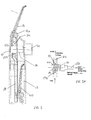
- a mouth cavity irrigation device comprises a main body 10 and an elongate, generally tubular reservoir 12 removably connected thereto, by, for example, a bayonet fitting, to provide a handle member.
- the reservoir holds a quantity of fluid 14, such as water, and can be removed from the main body 10 so as to be cleaned or emptied of or filled with liquid.
- the main body 10 has an outlet 16 to which is removably and rotatably connected, by means of, for example, a push-fit arrangement, an elongate, generally frusto-conical nozzle 18 having a generally central channel 19 which runs from an inlet 21 to a relatively narrower outlet 24.
- the outlet 16 of the main body 10 is disposed at an angle to the vertical axis 20 of the main body 10 and, in this case, the reservoir 12 so that the nozzle 18, when connected to the main body 10, is also disposed at an angle to the vertical axis 20.
- the angle in this case is around 45°, but may be any convenient angle.
- the nozzle 18 is curved or bent (at 22) close to its outlet 24. It should be noted that the main body 10 and the reservoir 12 may also be at an angle to each other.
- a manually-operated pump 26 is housed within the main body 10 and a dip tube 28 is connected at one end to a stepped cylinder 29 forming part of the pump 26, the other end of the dip tube 28 extending into the reservoir 12.
- Space is also provided in the reservoir 12 to store one or more spare or additional nozzles 40, when the device is not in use and (preferably) when the reservoir 12 is empty of liquid but connected to the main body 10.
- the pump 26 comprises a stepped cylinder 29, closed at one end and having an inlet (connected to the dip tube 28).
- the diameter of the cylinder 29 is narrower at the closed end, as shown.
- the wider, open end of the cylinder 29 is provided with a piston 36, the outer circumference of which is in substantially fluid-tight, slidable engagement with the inner surface of the cylinder 29.
- Operation of the pump 26 is effected by an arrangement 30 comprising a tube 32 which is in fluid communication with the channel 19 in the nozzle 18 via a resiliently flexible tube 34 connected at or adjacent one end of the tube 32.
- the tube 32 extends through an opening in the piston 36 into the cylinder 29, the end 33 of the tube 32 which extends into the cylinder 29 being smaller than the rest to locate with a spring (see Figure 1A).
- a manually operable button 41 which activates the arrangement 30 is provided on the outer wall of the main body 10.
- the reservoir 12 is first filled with, for example, water 14 up to a line or marking 15 indicating the maximum fluid level.
- the reservoir 12 may be required to be filled up to a maximum of 37.5mL.
- the reservoir 12 is then connected to the main body 10, and the nozzle 18 is connected to the outlet 16 of the main body 10, and rotated relative thereto, as required, to obtain the desired angle of the nozzle 18 relative to the device.
- the device can be held in the right or left hand as required.
- the dip tube 28 and stepped cylinder 29 must first be filled with water.
- the button 41 When the button 41 is pressed, the arrangement, consisting of the pipe 32 and the piston 36, extends further into the cylinder 29, until the piston 36 reaches the "step" at which the cylinder 29 narrows, and the smaller diameter 33 of the tube 32 extends into the section of the cylinder denoted 29a.
- a spring 100 Within the section of the cylinder denoted 29a there is provided a spring 100 ( Figure 1A) which is compressed as the smaller diameter end 33 of the tube 32 extends towards and into the cylinder section 29a.
- the pressure in the cylinder is increased.
- the spring (not shown) in the cylinder section 29a expands, pushing the tube 32 and the piston 36 back to their initial positions and thereby decreasing the pressure in the cylinder 29.
- This action causes the inlet valve to open and water to flow up the dip tube 28 and into the cylinder 29, until the pressure differential between the reservoir 12 and the cylinder 29 is equalised, at which point the inlet valve closes.
- the device is ready for use.
- An outlet valve 104 ( Figure 1A) may be provided in the tube 32, between the tube 32 and the flexible tube 34, or even outside the pump in, for example, the flexible tube 34 itself.
- the outlet valve 104 may be a ball valve comprising a ball which closes against a seating when there is negative pressure at 29.
- the outlet valve may be a sleeve valve whereby an aperture is provided close to the small diameter end of the tube 32, the aperture being closed by the piston when the device is not in use.
- a predetermined fixed volume of water is ejected from the nozzle outlet 24 into the mouth cavity. If, for example, the reservoir 12 holds 37.5mL of water, the device could be arranged to dispense 50 doses of 0.75mL each, after which the reservoir would need to be refilled. It is likely that a complete operation would require several activations (i.e. pushes) of the pump 26. It should be noted that the user also has the option to operate the unit using partial strokes or pushes of the button so that less than the predetermined fixed volume of water is dispensed. The user may also have the option to vary the rate or frequency at which the button is pushed. These options provide the user with substantially more control over the flow rate than prior art devices.
- the water to be discharged from the device could be initially pressurised by, for example, a spring activated piston, and water output could be controlled by means of a valve or the like, controllable by the user. Water discharge could then be continuous or intermittent, as desired.
- a mouth cavity irrigation device is substantially the same in all respects to the exemplary embodiment described with reference to Figure 1, except that the outlet 16 of the main body 10 is not disposed at an angle to the vertical axis 20 of the main body, and instead the nozzle 18 extends upwardly from the main body 10, substantially in line therewith.
- a mouth cavity irrigation device is similar in many respects to the first and second exemplary embodiments described above.
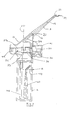
- the main body 10 and the reservoir 12 are both generally cylindrical (although other shapes are envisaged) and are connected together to provide a relatively narrow, elongate structure, with the nozzle 18 removably connected to a nozzle holder which is removably connected at the top of the main body as shown.
- the nozzle holder 18a is rotatable (about a substantially vertical axis) relative to the main body 10 and the nozzle 18, which is disposed at an approximately 20° angle thereto, is rotatable relative to the nozzle holder 18a. It will be appreciated that any convenient nozzle angle (including 0°) is intended to be encompassed by the invention.
- the pump 26 is once again a generally elongate structure comprising a cylinder 29, an inlet and an outlet, but the pump 26 is somewhat different so as to substantially reduce the diameter of the device required to accommodate it.
- the structure and operation of the pump 26 in the third exemplary embodiment is substantially the same as that described with reference to the first exemplary embodiment, except that the tube 32 ( Figure 1) is replaced by a solid member 132 which pushes the piston 36 into the cylinder 29 when the button is pressed.
- the outlet and outlet valve 133 (connected to the tube 34 leading to the nozzle 18) is provided for the cylinder 29, and (in the arrangement shown) diametrically opposite the inlet and inlet valve 134.
Landscapes
- Health & Medical Sciences (AREA)
- Dentistry (AREA)
- Epidemiology (AREA)
- Life Sciences & Earth Sciences (AREA)
- Animal Behavior & Ethology (AREA)
- General Health & Medical Sciences (AREA)
- Public Health (AREA)
- Veterinary Medicine (AREA)
- Infusion, Injection, And Reservoir Apparatuses (AREA)
- Nozzles (AREA)
Applications Claiming Priority (2)
| Application Number | Priority Date | Filing Date | Title |
|---|---|---|---|
| GB0025845A GB2368021A (en) | 2000-10-21 | 2000-10-21 | Mouth cavity irrigation device |
| GB0025845 | 2000-10-21 |
Publications (2)
| Publication Number | Publication Date |
|---|---|
| EP1201201A2 true EP1201201A2 (fr) | 2002-05-02 |
| EP1201201A3 EP1201201A3 (fr) | 2003-03-19 |
Family
ID=9901749
Family Applications (1)
| Application Number | Title | Priority Date | Filing Date |
|---|---|---|---|
| EP01308885A Withdrawn EP1201201A3 (fr) | 2000-10-21 | 2001-10-18 | Unité d'irrigation de la cavité buccale |
Country Status (3)
| Country | Link |
|---|---|
| US (1) | US20020082545A1 (fr) |
| EP (1) | EP1201201A3 (fr) |
| GB (1) | GB2368021A (fr) |
Cited By (2)
| Publication number | Priority date | Publication date | Assignee | Title |
|---|---|---|---|---|
| WO2009077919A3 (fr) * | 2007-12-18 | 2009-08-27 | Koninklijke Philips Electronics, N.V. | Système électromécanique pour nettoyage interproximal |
| WO2013190428A1 (fr) * | 2012-06-22 | 2013-12-27 | Koninklijke Philips N.V. | Pompe entraînée par un ressort destinée à distribuer des jets discontinus de liquide |
Families Citing this family (8)
| Publication number | Priority date | Publication date | Assignee | Title |
|---|---|---|---|---|
| DE10323603A1 (de) * | 2003-05-20 | 2004-12-30 | Ing. Erich Pfeiffer Gmbh | Dosiervorrichtung mit einer Pumpeinrichtung |
| AT502551B1 (de) * | 2005-06-15 | 2010-11-15 | Arc Seibersdorf Res Gmbh | Verfahren und bildauswertungseinheit zur szenenanalyse |
| BRPI0821232A2 (pt) * | 2007-12-18 | 2015-06-16 | Koninkl Philips Electronics Nv | Comutador multifuncional para um utensílio de cuidado oral, e, utensílio de cuidado oral. |
| US8376192B2 (en) | 2008-03-24 | 2013-02-19 | Mary Kay Inc. | Apparatus for dispensing fluids using a press-fit diptube |
| USD636668S1 (en) | 2008-03-24 | 2011-04-26 | Mary Kay Inc. | Dip tubes |
| US9789502B2 (en) | 2008-06-05 | 2017-10-17 | Mary Kay Inc. | Apparatus for dispensing fluids using a removable bottle |
| BR112012000692A2 (pt) * | 2009-07-14 | 2017-05-30 | Koninl Philips Electronics Nv | aparelho de limpeza bucal de gotejamento de líquido |
| RU2635008C2 (ru) * | 2014-05-16 | 2017-11-08 | Конинклейке Филипс Н.В. | Устройство для очистки полости рта, имеющее регулируемые динамические характеристики текучей среды |
Citations (2)
| Publication number | Priority date | Publication date | Assignee | Title |
|---|---|---|---|---|
| GB2018605A (en) | 1978-03-28 | 1979-10-24 | Wright W F | Dental cleaning device |
| US5197458A (en) | 1989-06-23 | 1993-03-30 | Ricoh Elemex Corporation | Mouth cavity sanitary device |
Family Cites Families (8)
| Publication number | Priority date | Publication date | Assignee | Title |
|---|---|---|---|---|
| FR1400926A (fr) * | 1964-07-11 | 1965-05-28 | Appareil de prophylaxie dentaire | |
| DE2548580A1 (de) * | 1975-10-30 | 1977-05-05 | Moser Gmbh Kuno | Wasserfuehrung fuer mundduschen |
| DE3516436A1 (de) * | 1985-05-08 | 1986-11-13 | Petz Elektro GmbH, 8641 Haßlach | Munddusche |
| US5086756A (en) * | 1991-01-03 | 1992-02-11 | Powell James R | Hand operated oral irrigation device for packaged liquids |
| DE4306527A1 (de) * | 1993-03-03 | 1994-09-08 | Heel Klaus Dipl Ing Designer F | Reisemunddusche |
| JPH0833656A (ja) * | 1994-07-26 | 1996-02-06 | Matsushita Electric Works Ltd | 口腔洗浄器 |
| US6030215A (en) * | 1998-09-04 | 2000-02-29 | Ellion; M. Edmund | Hand-held self-contained oral irrigation device |
| DE29909633U1 (de) * | 1999-06-01 | 1999-09-09 | Hartmann, Klaus, 50858 Köln | Munddusche |
-
2000
- 2000-10-21 GB GB0025845A patent/GB2368021A/en not_active Withdrawn
-
2001
- 2001-10-18 US US09/982,987 patent/US20020082545A1/en not_active Abandoned
- 2001-10-18 EP EP01308885A patent/EP1201201A3/fr not_active Withdrawn
Patent Citations (2)
| Publication number | Priority date | Publication date | Assignee | Title |
|---|---|---|---|---|
| GB2018605A (en) | 1978-03-28 | 1979-10-24 | Wright W F | Dental cleaning device |
| US5197458A (en) | 1989-06-23 | 1993-03-30 | Ricoh Elemex Corporation | Mouth cavity sanitary device |
Cited By (6)
| Publication number | Priority date | Publication date | Assignee | Title |
|---|---|---|---|---|
| WO2009077919A3 (fr) * | 2007-12-18 | 2009-08-27 | Koninklijke Philips Electronics, N.V. | Système électromécanique pour nettoyage interproximal |
| US8668660B2 (en) | 2007-12-18 | 2014-03-11 | Koninklijke Philips N.V. | Electromechanical system for interproximal cleaning |
| WO2013190428A1 (fr) * | 2012-06-22 | 2013-12-27 | Koninklijke Philips N.V. | Pompe entraînée par un ressort destinée à distribuer des jets discontinus de liquide |
| JP2015527101A (ja) * | 2012-06-22 | 2015-09-17 | コーニンクレッカ フィリップス エヌ ヴェ | 液体の離散的な噴出を分注するためのバネ駆動ポンプ |
| RU2640772C2 (ru) * | 2012-06-22 | 2018-01-11 | Конинклейке Филипс Н.В. | Насос с пружинным приводом для выдачи отдельных выбросов жидкости |
| US10299884B2 (en) | 2012-06-22 | 2019-05-28 | Koninklijke Philips N.V. | Spring driven pump for dispensing discrete bursts of liquid |
Also Published As
| Publication number | Publication date |
|---|---|
| GB0025845D0 (en) | 2000-12-06 |
| US20020082545A1 (en) | 2002-06-27 |
| GB2368021A (en) | 2002-04-24 |
| EP1201201A3 (fr) | 2003-03-19 |
Similar Documents
| Publication | Publication Date | Title |
|---|---|---|
| US4803974A (en) | Oral lavage apparatus | |
| US6689078B1 (en) | Self-contained oral cleaning device | |
| CN206120478U (zh) | 牙齿清洁器具 | |
| CN206007389U (zh) | 牙齿清洁器具及与其一起使用的清洁工具 | |
| CN205964205U (zh) | 清洁器具 | |
| CN206102768U (zh) | 牙齿清洁器具 | |
| CN106137437B (zh) | 清洁器具 | |
| CN106137429B (zh) | 清洁器具 | |
| JP6549672B2 (ja) | 清掃器具 | |
| KR101980614B1 (ko) | 세척 기구 | |
| US6030215A (en) | Hand-held self-contained oral irrigation device | |
| CA2581679A1 (fr) | Systeme d'hygiene buccale, dispositifs d'hygiene buccale et procedes d'utilisation | |
| JPH05502394A (ja) | 液自己保持型手持ちビデ | |
| CN106137439A (zh) | 清洁器具 | |
| US4700892A (en) | Misting and watering can | |
| WO2004021958A1 (fr) | Dispositif d'hygiene buccale autonome | |
| US5833675A (en) | Irrigator device | |
| US20110070016A1 (en) | Water pump toothbrush | |
| CN107847307A (zh) | 具有流体输送系统的牙齿清洁器具 | |
| JP2018069071A (ja) | 清掃器具 | |
| WO2004060259A3 (fr) | Hydropulseur a main | |
| US20020082545A1 (en) | Mouth cavity irrigation unit | |
| WO2005076818A2 (fr) | Dispositif de lavage oral autonome | |
| US20050173560A1 (en) | Trigger sprayer with ergonomic trigger | |
| EP0117947A1 (fr) | Appareil distributeur de fluide |
Legal Events
| Date | Code | Title | Description |
|---|---|---|---|
| PUAI | Public reference made under article 153(3) epc to a published international application that has entered the european phase |
Free format text: ORIGINAL CODE: 0009012 |
|
| AK | Designated contracting states |
Kind code of ref document: A2 Designated state(s): AT BE CH CY DE DK ES FI FR GB GR IE IT LI LU MC NL PT SE TR |
|
| AX | Request for extension of the european patent |
Free format text: AL;LT;LV;MK;RO;SI |
|
| PUAL | Search report despatched |
Free format text: ORIGINAL CODE: 0009013 |
|
| AK | Designated contracting states |
Kind code of ref document: A3 Designated state(s): AT BE CH CY DE DK ES FI FR GB GR IE IT LI LU MC NL PT SE TR Designated state(s): AT BE CH CY DE DK ES FI FR GB GR IE IT LI LU MC NL PT SE TR |
|
| AX | Request for extension of the european patent |
Extension state: AL LT LV MK RO SI |
|
| AKX | Designation fees paid | ||
| REG | Reference to a national code |
Ref country code: DE Ref legal event code: 8566 |
|
| STAA | Information on the status of an ep patent application or granted ep patent |
Free format text: STATUS: THE APPLICATION IS DEEMED TO BE WITHDRAWN |
|
| 18D | Application deemed to be withdrawn |
Effective date: 20030920 |