EP1201343A2 - Procédé d'usinage par électrochimie, électrode pour le procédé, et aubes de turbines avec des passages de refroidissemnet avec écoulement turbulent - Google Patents
Procédé d'usinage par électrochimie, électrode pour le procédé, et aubes de turbines avec des passages de refroidissemnet avec écoulement turbulent Download PDFInfo
- Publication number
- EP1201343A2 EP1201343A2 EP01308777A EP01308777A EP1201343A2 EP 1201343 A2 EP1201343 A2 EP 1201343A2 EP 01308777 A EP01308777 A EP 01308777A EP 01308777 A EP01308777 A EP 01308777A EP 1201343 A2 EP1201343 A2 EP 1201343A2
- Authority
- EP
- European Patent Office
- Prior art keywords
- electrode
- hole
- rows
- projections
- bucket
- Prior art date
- Legal status (The legal status is an assumption and is not a legal conclusion. Google has not performed a legal analysis and makes no representation as to the accuracy of the status listed.)
- Granted
Links
Images
Classifications
-
- B—PERFORMING OPERATIONS; TRANSPORTING
- B23—MACHINE TOOLS; METAL-WORKING NOT OTHERWISE PROVIDED FOR
- B23H—WORKING OF METAL BY THE ACTION OF A HIGH CONCENTRATION OF ELECTRIC CURRENT ON A WORKPIECE USING AN ELECTRODE WHICH TAKES THE PLACE OF A TOOL; SUCH WORKING COMBINED WITH OTHER FORMS OF WORKING OF METAL
- B23H9/00—Machining specially adapted for treating particular metal objects or for obtaining special effects or results on metal objects
- B23H9/14—Making holes
-
- B—PERFORMING OPERATIONS; TRANSPORTING
- B23—MACHINE TOOLS; METAL-WORKING NOT OTHERWISE PROVIDED FOR
- B23H—WORKING OF METAL BY THE ACTION OF A HIGH CONCENTRATION OF ELECTRIC CURRENT ON A WORKPIECE USING AN ELECTRODE WHICH TAKES THE PLACE OF A TOOL; SUCH WORKING COMBINED WITH OTHER FORMS OF WORKING OF METAL
- B23H3/00—Electrochemical machining, i.e. removing metal by passing current between an electrode and a workpiece in the presence of an electrolyte
- B23H3/04—Electrodes specially adapted therefor or their manufacture
-
- B—PERFORMING OPERATIONS; TRANSPORTING
- B23—MACHINE TOOLS; METAL-WORKING NOT OTHERWISE PROVIDED FOR
- B23H—WORKING OF METAL BY THE ACTION OF A HIGH CONCENTRATION OF ELECTRIC CURRENT ON A WORKPIECE USING AN ELECTRODE WHICH TAKES THE PLACE OF A TOOL; SUCH WORKING COMBINED WITH OTHER FORMS OF WORKING OF METAL
- B23H9/00—Machining specially adapted for treating particular metal objects or for obtaining special effects or results on metal objects
- B23H9/10—Working turbine blades or nozzles
-
- F—MECHANICAL ENGINEERING; LIGHTING; HEATING; WEAPONS; BLASTING
- F05—INDEXING SCHEMES RELATING TO ENGINES OR PUMPS IN VARIOUS SUBCLASSES OF CLASSES F01-F04
- F05B—INDEXING SCHEME RELATING TO WIND, SPRING, WEIGHT, INERTIA OR LIKE MOTORS, TO MACHINES OR ENGINES FOR LIQUIDS COVERED BY SUBCLASSES F03B, F03D AND F03G
- F05B2260/00—Function
- F05B2260/20—Heat transfer, e.g. cooling
- F05B2260/221—Improvement of heat transfer
- F05B2260/222—Improvement of heat transfer by creating turbulence
Definitions
- the present invention relates to an electrode for electrochemical machining interior surfaces of cooling passages for a turbine bucket, a method therefor and a turbine bucket having the machined interior surface.
- STEM Electrochemical machining known as shaped-tube electrochemical machining (STEM) is used for drilling small, deep holes in electrically conductive materials.
- STEM is a non-contact electrochemical drilling process for producing holes with high aspect ratios such as 300:1.
- the aspect ratio is the ratio of the length or depth of the hole to the largest lateral dimension, e.g., diameter, of the hole which, in certain specific applications, can be as small as a few millimeters.
- STEM is used, e.g., to form the deep holes used as cooling passages for the buckets in gas turbines.
- Gas turbine efficiencies are directly proportional to the temperature of turbine gases flowing along the hot gas path and driving the turbine blades.
- Gas turbines typically have operating temperatures on the order of 2700°F.
- the buckets are manufactured from advanced materials and typically include smooth bore cooling passages for flowing a cooling medium for cooling the buckets.
- the cooling medium is typically compressor discharge air.
- the passages also conventionally extend from the bucket root to the bucket tip. While smooth-bore passages have been utilized, turbulence promoters, e.g., turbulators, are used in many gas turbine buckets to enhance the internal heat transfer coefficient.
- the heat transfer enhancement can be as high as 2.5 times as compared with smooth-bore passages for the same cooling flow rate.
- Turbulators conventionally comprise internal ridges or roughened surfaces along the interior surfaces of the cooling passages and are typically cast inside the cooling passages using ceramic cores. In many currently used turbines, however, many of the buckets have interior cooling passages with smooth interior wall surfaces formed by the casting process and therefore do not obtain the enhanced cooling effects otherwise available with turbulators.
- the STEM technique identified above and described in the above-identified applications incorporated herein by reference employ an electrode having an insulating dielectric material or coating applied on the electrode surface in a pattern which, in conjunction with an electrolyte and the application of an electrical current between the electrode and the workpiece (bucket) displaces, i.e., dissolves, metal from the adjacent parts of the cooling passage wall to form projections and grooves along the interior surface. That is, the metallic portions of the interior surface of the cooling passage wall directly adjacent the insulated portions of the electrode when inserted into the preformed hole are not electrochemically removed, while the portions thereof directly adjacent the non-insulated portions of the electrode are electrochemically removed to form grooves in the interior wall portions of the cooling passage defining the projections therebetween. Certain of the foregoing applications are directed to the electrochemical machining process for forming projections and grooves along the interior wall surfaces.
- an electrochemical machining process for forming axially spaced rows of projections, i.e., turbulators, along the interior wall surfaces of the cooling passages with gaps in each row to form cooling passages in buckets having enhanced heat transfer characteristics, i.e., enhanced internal heat transfer coefficients.
- the present invention provides an electrode having an insulating dielectric coating about its entire exterior surface. Portions of the coating on the electrode are removed to form a desired turbulator pattern. That is, retained insulated portions of the electrode will correspond to the locations of the projections to be formed along the interior wall surface of the cooling passages of the bucket.
- a particular advantage of the turbulator pattern described above is that the electrode is relatively easy to fabricate. Moreover, the resulting pattern of turbulators along the interior surface of the cooling passages have greatly enhanced heat transfer characteristics. Particularly, the radial flow of cooling medium during turbine operation from the bucket root toward the bucket tip interacts with the bucket rotation and creates a coriolis effect to flow the cooling medium from the leading face (suction side) toward the trailing face (pressure side). The combination of this secondary flow with the radial flow forms a complicated flow field within the cooling passage having enhanced heat transfer characteristics. The radial flow sheds vortices from the turbulators and the interruptions, i.e., gaps, and the secondary flow circulates the vortices around the passage walls to enhance the surface heat transfer coefficient.
- a process for forming interrupted raised projections and grooves therebetween perimetrically about an interior surface of a preformed elongated hole in a workpiece comprising the steps of (a) locating within the hole an electrode having electrical insulating material arranged in axially spaced, perimetrically extending rows, interrupted by at least one gap, forming a pattern of insulated and non-insulated portions of the electrode about an outer surface of the electrode in general opposition to intended locations of the projections and grooves, respectively, about the interior surface of the hole, (b) flowing an electrolyte between the electrode and the interior surface of the hole of the workpiece and (c) passing an electric current between the electrode and the workpiece to form the perimetrically interrupted axially spaced rows of projections and grooves along the interior surface of the hole.
- a bucket for a turbine having at least one generally elongated cooling passage extending along the bucket generally from the bucket root to the bucket tip and having an axis, the cooling passage having a perimetrical interior surface with rows of axially spaced raised projections extending generally perpendicular to and toward the axis, each projection being interrupted by a gap defining a recess extending generally in a direction away from the axis.
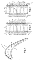
- a cooling passage 16 formed by an electrochemical machining process according to the present invention using an electrode 18 disposed within a preformed, e.g., precast or predrilled hole 16.
- electrode 18 may be formed of a body 19 comprised of a hollow cylindrical metal tube having a dielectric, i.e., electrically insulating, coating 20 formed along an exterior surface.
- the dielectric coating 20 is arranged in a pattern of rows 22 which are axially spaced one from the other in the axial direction of the cooling passage 16 (the cooling passages 16 extend generally radially along the turbine bucket but for purposes of describing the cooling passage per se , the term "axial" or "axially” is used to define the length direction of the cooling passage).
- the electrode 18 is initially entirely coated about its perimetrical surface, in the illustrated form that surface being the cylindrical exterior surface of the electrode 18.
- the coating is then removed, for example, by laser ablation, to form the pattern of dielectrically insulated portions, i.e., the rows 22, and non-insulated portions, i.e., the portions 24 between the rows 22 of dielectric material.
- Gaps 26 are also provided in the rows 22 of insulating material, the gaps 26 interrupting the rows 22.
- the portions 24 and gaps 26 thus comprise the non-insulated electrode portions which cooperate with an electrolyte passed between the electrode 18 and the walls 16 of the cooling passages and the application of an electrical current between electrode 18 and the bucket 10 to remove metal along the interior wall surface directly adjacent these exposed non-insulated metal portions to form the grooves 29 between projections 30 along the interior wall surface.
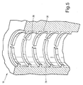
- the gaps 26 are formed in the pattern of insulating material to provide recesses or gaps 28 in the ridges or projections 30 formed by the removal of the material, at least two gaps per row being preferred. For example, as illustrated in Figure 5, the gaps 26 in the insulating material of the rows 22 of the electrode form the gaps 28 along the rows 30 which form the turbulators of the cooling passages.
- an electrolyte solution 32 is circulated through the. body of the electrode 18 for return flow between the electrode and the interior wall surfaces, as indicated by the arrows 34.
- the electrode 18 may be solid and the electrolyte flow may be commenced adjacent one end of the passage for flow toward and exiting from the opposite end of the passage 16. Consequently, the electrolyte flows between the interior wall surface of passage 16 and the non-insulated and insulated portions of the metal electrode 18.
- the gaps 28 of adjacent rows 30 are preferably axially misaligned with one another.
- the gaps 28, however, can be axially aligned with one another, if desired.
- a greater number of gaps 28 may be provided if desired.
- the combination of the gaps and projections forms a desirable complicated flow field within the cooling passages as the bucket rotates about the axis of the turbine.
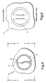
- the radial flow from the bucket root toward the bucket tip interacts with the bucket rotation and creates a coriolis effect to flow the cooling medium from the leading face (suction side) toward the trailing face (pressure side) in a flow pattern, as illustrated by the arrows in Figure 6.
- the radial flow sheds vortices from the projections 30 and the interruptions, i.e., the gaps 28 and the secondary flow circulates the vortices around the passage walls to enhance the surface heat transfer coefficient.
Landscapes
- Engineering & Computer Science (AREA)
- Mechanical Engineering (AREA)
- Physics & Mathematics (AREA)
- Thermal Sciences (AREA)
- Manufacturing & Machinery (AREA)
- Chemical & Material Sciences (AREA)
- Chemical Kinetics & Catalysis (AREA)
- Electrochemistry (AREA)
- Electrical Discharge Machining, Electrochemical Machining, And Combined Machining (AREA)
- Turbine Rotor Nozzle Sealing (AREA)
Applications Claiming Priority (2)
| Application Number | Priority Date | Filing Date | Title |
|---|---|---|---|
| US09/688,579 US6416283B1 (en) | 2000-10-16 | 2000-10-16 | Electrochemical machining process, electrode therefor and turbine bucket with turbulated cooling passage |
| US688579 | 2000-10-16 |
Publications (3)
| Publication Number | Publication Date |
|---|---|
| EP1201343A2 true EP1201343A2 (fr) | 2002-05-02 |
| EP1201343A3 EP1201343A3 (fr) | 2004-04-28 |
| EP1201343B1 EP1201343B1 (fr) | 2008-06-25 |
Family
ID=24764970
Family Applications (1)
| Application Number | Title | Priority Date | Filing Date |
|---|---|---|---|
| EP01308777A Expired - Lifetime EP1201343B1 (fr) | 2000-10-16 | 2001-10-16 | Aubes de turbines avec des passages de refroidissemnet avec écoulement turbulent et électrode pour usinage par électrochimie |
Country Status (3)
| Country | Link |
|---|---|
| US (1) | US6416283B1 (fr) |
| EP (1) | EP1201343B1 (fr) |
| JP (1) | JP4138288B2 (fr) |
Cited By (13)
| Publication number | Priority date | Publication date | Assignee | Title |
|---|---|---|---|---|
| EP1283327A3 (fr) * | 2001-08-09 | 2004-04-21 | General Electric Company | Méthode permettant d'améliorer le transfert de chaleur dans un canal de refroidissement pourvu de turbulateurs |
| WO2004057157A1 (fr) * | 2002-12-21 | 2004-07-08 | John Macdonald | Aube de turbine |
| EP1442817A3 (fr) * | 2002-03-18 | 2005-02-09 | General Electric Company | Procédé et dispositif pour la révision des canaux de refroidissement d'une aube de turbine |
| DE102006044416A1 (de) * | 2006-09-18 | 2008-03-27 | Siemens Ag | Verfahren zum elektrochemischen Be- oder Entschichten von Bauteilen |
| EP1561902A3 (fr) * | 2004-02-09 | 2009-01-07 | United Technologies Corporation | Aube de turbine avec promoteurs de turbulence |
| EP2022586A3 (fr) * | 2007-03-22 | 2011-11-02 | General Electric Company | Procédés et systèmes pour la formation de trous de refroidissement dotés d'entrées circulaires et de sorties non circulaires |
| EP1972403A3 (fr) * | 2007-03-22 | 2011-11-02 | General Electric Company | Procédés et systèmes pour la formation de trous de refroidissement avec écoulement turbulent |
| EP2131108A3 (fr) * | 2008-06-06 | 2014-01-01 | United Technologies Corporation | Conception d'un trou de refroidissement à film à vortex inversé |
| US8673405B2 (en) | 2006-08-08 | 2014-03-18 | Siemens Aktiengesellschaft | Method for producing a wear layer |
| WO2015032936A1 (fr) * | 2013-09-09 | 2015-03-12 | Siemens Aktiengesellschaft | Chambre de combustion d'une turbine à gaz et outil et procédé permettant de produire des canaux de refroidissement dans un composant d'une turbine à gaz |
| CN108526625A (zh) * | 2018-03-23 | 2018-09-14 | 南京航空航天大学 | 大厚度电解切割矩形截面异形管电极与加工方法 |
| CN108705268A (zh) * | 2018-08-15 | 2018-10-26 | 江苏振江新能源装备股份有限公司 | 陆上风力发电机法兰加工工艺 |
| CN110732849A (zh) * | 2019-11-18 | 2020-01-31 | 中国航发贵州黎阳航空动力有限公司 | 薄壁钣焊结构件腔体内壁通孔电火花加工方法 |
Families Citing this family (28)
| Publication number | Priority date | Publication date | Assignee | Title |
|---|---|---|---|---|
| US6910620B2 (en) * | 2002-10-15 | 2005-06-28 | General Electric Company | Method for providing turbulation on the inner surface of holes in an article, and related articles |
| US6754955B1 (en) * | 2003-01-30 | 2004-06-29 | General Electric Company | Method or repairing trailing edge portions of partitions in turbine diaphragms |
| US6997679B2 (en) * | 2003-12-12 | 2006-02-14 | General Electric Company | Airfoil cooling holes |
| US7114916B2 (en) * | 2004-02-09 | 2006-10-03 | United Technologies Corporation | Tailored turbulation for turbine blades |
| US20050218089A1 (en) * | 2004-03-30 | 2005-10-06 | General Electric Company | Flushing and filtering system for electroerosion machining |
| US7824526B2 (en) * | 2006-12-11 | 2010-11-02 | General Electric Company | Adaptive spindle assembly for electroerosion machining on a CNC machine tool |
| US7901180B2 (en) * | 2007-05-07 | 2011-03-08 | United Technologies Corporation | Enhanced turbine airfoil cooling |
| JP4562801B2 (ja) * | 2007-05-09 | 2010-10-13 | 株式会社カンタム14 | シリコン基材の加工方法および加工装置 |
| US8511992B2 (en) * | 2008-01-22 | 2013-08-20 | United Technologies Corporation | Minimization of fouling and fluid losses in turbine airfoils |
| US8778147B2 (en) * | 2008-05-12 | 2014-07-15 | General Electric Company | Method and tool for forming non-circular holes using a selectively coated electrode |
| US8900424B2 (en) * | 2008-05-12 | 2014-12-02 | General Electric Company | Electrode and electrochemical machining process for forming non-circular holes |
| US20090304494A1 (en) * | 2008-06-06 | 2009-12-10 | United Technologies Corporation | Counter-vortex paired film cooling hole design |
| US9333577B2 (en) * | 2008-08-29 | 2016-05-10 | General Electric Company | Electro discharge machining apparatus and method |
| US8560110B2 (en) * | 2009-06-19 | 2013-10-15 | General Electric Company | Electroerosion control system and a dual mode control system |
| CN102133665A (zh) * | 2010-08-25 | 2011-07-27 | 中国船舶重工集团公司第七○四研究所 | 电蚀加工阀套全周边工艺装置 |
| US10113435B2 (en) | 2011-07-15 | 2018-10-30 | United Technologies Corporation | Coated gas turbine components |
| US9296039B2 (en) | 2012-04-24 | 2016-03-29 | United Technologies Corporation | Gas turbine engine airfoil impingement cooling |
| US9243502B2 (en) | 2012-04-24 | 2016-01-26 | United Technologies Corporation | Airfoil cooling enhancement and method of making the same |
| US9995148B2 (en) | 2012-10-04 | 2018-06-12 | General Electric Company | Method and apparatus for cooling gas turbine and rotor blades |
| US9850762B2 (en) | 2013-03-13 | 2017-12-26 | General Electric Company | Dust mitigation for turbine blade tip turns |
| CA2950011C (fr) | 2014-05-29 | 2020-01-28 | General Electric Company | Generateur de turbulence fastback |
| US10422235B2 (en) | 2014-05-29 | 2019-09-24 | General Electric Company | Angled impingement inserts with cooling features |
| US9957816B2 (en) | 2014-05-29 | 2018-05-01 | General Electric Company | Angled impingement insert |
| US10364684B2 (en) | 2014-05-29 | 2019-07-30 | General Electric Company | Fastback vorticor pin |
| WO2016025054A2 (fr) | 2014-05-29 | 2016-02-18 | General Electric Company | Éléments de turbine à gaz ayant des caractéristiques de refroidissement |
| US10280785B2 (en) | 2014-10-31 | 2019-05-07 | General Electric Company | Shroud assembly for a turbine engine |
| US10233775B2 (en) | 2014-10-31 | 2019-03-19 | General Electric Company | Engine component for a gas turbine engine |
| DE112018007681T5 (de) * | 2018-07-31 | 2021-03-11 | General Electric Company | Gekühltes schaufelblatt und herstellungsverfahren |
Family Cites Families (8)
| Publication number | Priority date | Publication date | Assignee | Title |
|---|---|---|---|---|
| DE2437047A1 (de) * | 1974-08-01 | 1976-02-12 | Skf Kugellagerfabriken Gmbh | Verfahren zur herstellung einer elektrode fuer die elektrolytische einarbeitung eines rillenmusters in die gewoelbte flaeche eines werkstuecks |
| US5695322A (en) * | 1991-12-17 | 1997-12-09 | General Electric Company | Turbine blade having restart turbulators |
| US5306401A (en) * | 1993-03-15 | 1994-04-26 | Fierkens Richard H J | Method for drilling cooling holes in turbine blades |
| US5738493A (en) * | 1997-01-03 | 1998-04-14 | General Electric Company | Turbulator configuration for cooling passages of an airfoil in a gas turbine engine |
| US5980209A (en) * | 1997-06-27 | 1999-11-09 | General Electric Co. | Turbine blade with enhanced cooling and profile optimization |
| US6200439B1 (en) * | 1998-11-05 | 2001-03-13 | General Electric Company | Tool for electrochemical machining |
| US6303193B1 (en) * | 1998-11-05 | 2001-10-16 | General Electric Company | Process for fabricating a tool used in electrochemical machining |
| US6234752B1 (en) * | 1999-08-16 | 2001-05-22 | General Electric Company | Method and tool for electrochemical machining |
-
2000
- 2000-10-16 US US09/688,579 patent/US6416283B1/en not_active Expired - Lifetime
-
2001
- 2001-10-15 JP JP2001316133A patent/JP4138288B2/ja not_active Expired - Fee Related
- 2001-10-16 EP EP01308777A patent/EP1201343B1/fr not_active Expired - Lifetime
Cited By (16)
| Publication number | Priority date | Publication date | Assignee | Title |
|---|---|---|---|---|
| EP1283327A3 (fr) * | 2001-08-09 | 2004-04-21 | General Electric Company | Méthode permettant d'améliorer le transfert de chaleur dans un canal de refroidissement pourvu de turbulateurs |
| EP1442817A3 (fr) * | 2002-03-18 | 2005-02-09 | General Electric Company | Procédé et dispositif pour la révision des canaux de refroidissement d'une aube de turbine |
| WO2004057157A1 (fr) * | 2002-12-21 | 2004-07-08 | John Macdonald | Aube de turbine |
| EP1561902A3 (fr) * | 2004-02-09 | 2009-01-07 | United Technologies Corporation | Aube de turbine avec promoteurs de turbulence |
| US8673405B2 (en) | 2006-08-08 | 2014-03-18 | Siemens Aktiengesellschaft | Method for producing a wear layer |
| DE102006044416A1 (de) * | 2006-09-18 | 2008-03-27 | Siemens Ag | Verfahren zum elektrochemischen Be- oder Entschichten von Bauteilen |
| EP2022586A3 (fr) * | 2007-03-22 | 2011-11-02 | General Electric Company | Procédés et systèmes pour la formation de trous de refroidissement dotés d'entrées circulaires et de sorties non circulaires |
| EP1972403A3 (fr) * | 2007-03-22 | 2011-11-02 | General Electric Company | Procédés et systèmes pour la formation de trous de refroidissement avec écoulement turbulent |
| EP2131108A3 (fr) * | 2008-06-06 | 2014-01-01 | United Technologies Corporation | Conception d'un trou de refroidissement à film à vortex inversé |
| WO2015032936A1 (fr) * | 2013-09-09 | 2015-03-12 | Siemens Aktiengesellschaft | Chambre de combustion d'une turbine à gaz et outil et procédé permettant de produire des canaux de refroidissement dans un composant d'une turbine à gaz |
| CN105531544A (zh) * | 2013-09-09 | 2016-04-27 | 西门子公司 | 用于燃气轮机的燃烧室以及用于制造燃气轮机部件中的冷却通道的方法和工具 |
| CN108526625A (zh) * | 2018-03-23 | 2018-09-14 | 南京航空航天大学 | 大厚度电解切割矩形截面异形管电极与加工方法 |
| CN108705268A (zh) * | 2018-08-15 | 2018-10-26 | 江苏振江新能源装备股份有限公司 | 陆上风力发电机法兰加工工艺 |
| CN108705268B (zh) * | 2018-08-15 | 2020-05-19 | 江苏振江新能源装备股份有限公司 | 陆上风力发电机法兰加工工艺 |
| CN110732849A (zh) * | 2019-11-18 | 2020-01-31 | 中国航发贵州黎阳航空动力有限公司 | 薄壁钣焊结构件腔体内壁通孔电火花加工方法 |
| CN110732849B (zh) * | 2019-11-18 | 2021-06-11 | 中国航发贵州黎阳航空动力有限公司 | 薄壁钣焊结构件腔体内壁通孔电火花加工方法 |
Also Published As
| Publication number | Publication date |
|---|---|
| US6416283B1 (en) | 2002-07-09 |
| JP2002180801A (ja) | 2002-06-26 |
| EP1201343A3 (fr) | 2004-04-28 |
| EP1201343B1 (fr) | 2008-06-25 |
| JP4138288B2 (ja) | 2008-08-27 |
Similar Documents
| Publication | Publication Date | Title |
|---|---|---|
| US6416283B1 (en) | Electrochemical machining process, electrode therefor and turbine bucket with turbulated cooling passage | |
| EP1283327B1 (fr) | Méthode permettant d'améliorer le transfert de chaleur dans un canal de refroidissement pourvu de turbulateurs | |
| US6554571B1 (en) | Curved turbulator configuration for airfoils and method and electrode for machining the configuration | |
| EP1215005B1 (fr) | Procédé d'usinage par électrochimie pour former des élements ayant une rugosité de surface sur une virole de turbine à gaz | |
| KR100526088B1 (ko) | 터빈 블레이드 | |
| US20030086785A1 (en) | Cooling passages and methods of fabrication | |
| EP1220729B1 (fr) | Procede et outil d'usinage electrochimique | |
| EP1607577B1 (fr) | Aube de turbine avec perçages de refroidissement par film d'air | |
| US6387242B1 (en) | Method and tool for electrochemical machining | |
| US6234752B1 (en) | Method and tool for electrochemical machining | |
| EP0735934B1 (fr) | Dispositif permettant de realiser des trous d'une forme particuliere dans des objets tels que des composants de turbine a gaz | |
| EP1098068A2 (fr) | Canal de refroidissement strié | |
| US6200439B1 (en) | Tool for electrochemical machining | |
| JP6133333B2 (ja) | 熱によって高い応力を受ける構成部材において表面付近冷却通路を形成する方法およびこのような通路を有する構成部材 | |
| US6267868B1 (en) | Method and tool for electrochemical machining | |
| JP2012082830A (ja) | タービン翼形部用の湾曲フィルム冷却孔 | |
| US20060163211A1 (en) | Article having diffuser holes and method of making same | |
| GB2117455A (en) | Axial flow turbine blade | |
| KR20080086380A (ko) | 객체 내에 홀을 형성하는 방법, ecm 장치 및 터빈 엔진구성요소 내에서 홀을 가공하는 시스템 | |
| MXPA02008085A (es) | Incremento del enfriamiento de devanado extremo de generador. | |
| JP2004218641A (ja) | 後縁冷却タービン部材およびその製造方法 | |
| JP3416184B2 (ja) | ガスタービン空冷動翼の翼先端部の冷却構造 |
Legal Events
| Date | Code | Title | Description |
|---|---|---|---|
| PUAI | Public reference made under article 153(3) epc to a published international application that has entered the european phase |
Free format text: ORIGINAL CODE: 0009012 |
|
| AK | Designated contracting states |
Kind code of ref document: A2 Designated state(s): AT BE CH CY DE DK ES FI FR GB GR IE IT LI LU MC NL PT SE TR |
|
| AX | Request for extension of the european patent |
Free format text: AL;LT;LV;MK;RO;SI |
|
| PUAL | Search report despatched |
Free format text: ORIGINAL CODE: 0009013 |
|
| AK | Designated contracting states |
Kind code of ref document: A3 Designated state(s): AT BE CH CY DE DK ES FI FR GB GR IE IT LI LU MC NL PT SE TR |
|
| AX | Request for extension of the european patent |
Extension state: AL LT LV MK RO SI |
|
| 17P | Request for examination filed |
Effective date: 20041028 |
|
| AKX | Designation fees paid |
Designated state(s): CH FR GB IT LI SE |
|
| REG | Reference to a national code |
Ref country code: DE Ref legal event code: 8566 |
|
| 17Q | First examination report despatched |
Effective date: 20061115 |
|
| GRAP | Despatch of communication of intention to grant a patent |
Free format text: ORIGINAL CODE: EPIDOSNIGR1 |
|
| RTI1 | Title (correction) |
Free format text: TURBINE BUCKET WITH TURBULATED COOLING PASSAGE AND ELECTRODE FOR ELECTOCHEMICAL MACHINING. |
|
| GRAS | Grant fee paid |
Free format text: ORIGINAL CODE: EPIDOSNIGR3 |
|
| GRAA | (expected) grant |
Free format text: ORIGINAL CODE: 0009210 |
|
| AK | Designated contracting states |
Kind code of ref document: B1 Designated state(s): CH FR GB IT LI SE |
|
| REG | Reference to a national code |
Ref country code: GB Ref legal event code: FG4D |
|
| REG | Reference to a national code |
Ref country code: CH Ref legal event code: NV Representative=s name: SERVOPATENT GMBH Ref country code: CH Ref legal event code: EP |
|
| REG | Reference to a national code |
Ref country code: SE Ref legal event code: TRGR |
|
| PLBE | No opposition filed within time limit |
Free format text: ORIGINAL CODE: 0009261 |
|
| STAA | Information on the status of an ep patent application or granted ep patent |
Free format text: STATUS: NO OPPOSITION FILED WITHIN TIME LIMIT |
|
| 26N | No opposition filed |
Effective date: 20090326 |
|
| REG | Reference to a national code |
Ref country code: FR Ref legal event code: PLFP Year of fee payment: 15 |
|
| REG | Reference to a national code |
Ref country code: FR Ref legal event code: PLFP Year of fee payment: 16 |
|
| REG | Reference to a national code |
Ref country code: FR Ref legal event code: PLFP Year of fee payment: 17 |
|
| REG | Reference to a national code |
Ref country code: FR Ref legal event code: PLFP Year of fee payment: 18 |
|
| PGFP | Annual fee paid to national office [announced via postgrant information from national office to epo] |
Ref country code: IT Payment date: 20190918 Year of fee payment: 19 Ref country code: SE Payment date: 20190923 Year of fee payment: 19 Ref country code: FR Payment date: 20190919 Year of fee payment: 19 |
|
| PGFP | Annual fee paid to national office [announced via postgrant information from national office to epo] |
Ref country code: GB Payment date: 20190923 Year of fee payment: 19 |
|
| PGFP | Annual fee paid to national office [announced via postgrant information from national office to epo] |
Ref country code: CH Payment date: 20190923 Year of fee payment: 19 |
|
| REG | Reference to a national code |
Ref country code: CH Ref legal event code: PCAR Free format text: NEW ADDRESS: WANNERSTRASSE 9/1, 8045 ZUERICH (CH) |
|
| REG | Reference to a national code |
Ref country code: CH Ref legal event code: PL |
|
| REG | Reference to a national code |
Ref country code: SE Ref legal event code: EUG |
|
| GBPC | Gb: european patent ceased through non-payment of renewal fee |
Effective date: 20201016 |
|
| PG25 | Lapsed in a contracting state [announced via postgrant information from national office to epo] |
Ref country code: FR Free format text: LAPSE BECAUSE OF NON-PAYMENT OF DUE FEES Effective date: 20201031 |
|
| PG25 | Lapsed in a contracting state [announced via postgrant information from national office to epo] |
Ref country code: CH Free format text: LAPSE BECAUSE OF NON-PAYMENT OF DUE FEES Effective date: 20201031 Ref country code: LI Free format text: LAPSE BECAUSE OF NON-PAYMENT OF DUE FEES Effective date: 20201031 Ref country code: GB Free format text: LAPSE BECAUSE OF NON-PAYMENT OF DUE FEES Effective date: 20201016 Ref country code: SE Free format text: LAPSE BECAUSE OF NON-PAYMENT OF DUE FEES Effective date: 20201017 |
|
| PG25 | Lapsed in a contracting state [announced via postgrant information from national office to epo] |
Ref country code: IT Free format text: LAPSE BECAUSE OF NON-PAYMENT OF DUE FEES Effective date: 20201016 |