EP1201369A2 - Mécanisme de serrage motorisé - Google Patents
Mécanisme de serrage motorisé Download PDFInfo
- Publication number
- EP1201369A2 EP1201369A2 EP01308690A EP01308690A EP1201369A2 EP 1201369 A2 EP1201369 A2 EP 1201369A2 EP 01308690 A EP01308690 A EP 01308690A EP 01308690 A EP01308690 A EP 01308690A EP 1201369 A2 EP1201369 A2 EP 1201369A2
- Authority
- EP
- European Patent Office
- Prior art keywords
- clamp
- cavity
- piston
- drive shaft
- piston rod
- Prior art date
- Legal status (The legal status is an assumption and is not a legal conclusion. Google has not performed a legal analysis and makes no representation as to the accuracy of the status listed.)
- Withdrawn
Links
Images



Classifications
-
- B—PERFORMING OPERATIONS; TRANSPORTING
- B25—HAND TOOLS; PORTABLE POWER-DRIVEN TOOLS; MANIPULATORS
- B25B—TOOLS OR BENCH DEVICES NOT OTHERWISE PROVIDED FOR, FOR FASTENING, CONNECTING, DISENGAGING, OR HOLDING
- B25B5/00—Clamps
- B25B5/06—Arrangements for positively actuating jaws
- B25B5/08—Arrangements for positively actuating jaws using cams
- B25B5/087—Arrangements for positively actuating jaws using cams actuated by a hydraulic or pneumatic piston
-
- Y—GENERAL TAGGING OF NEW TECHNOLOGICAL DEVELOPMENTS; GENERAL TAGGING OF CROSS-SECTIONAL TECHNOLOGIES SPANNING OVER SEVERAL SECTIONS OF THE IPC; TECHNICAL SUBJECTS COVERED BY FORMER USPC CROSS-REFERENCE ART COLLECTIONS [XRACs] AND DIGESTS
- Y10—TECHNICAL SUBJECTS COVERED BY FORMER USPC
- Y10S—TECHNICAL SUBJECTS COVERED BY FORMER USPC CROSS-REFERENCE ART COLLECTIONS [XRACs] AND DIGESTS
- Y10S269/00—Work holders
- Y10S269/903—Work holder for electrical circuit assemblages or wiring systems
Definitions
- Another object of the present invention is to provide a specially designed power clamp apparatus which utilizes a wedge lock system to move the clamp arm into a closed clamped position.
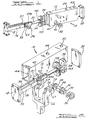
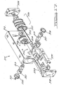
- Another object of the invention is to provide a unique new clamp mechanism wherein a unit assembly including a piston, a piston rod, a floating head member, and a link mechanism, are all assembled together prior to being inserted as a unit into the body of the clamp mechanism.
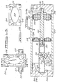
- the track mechanism is comprised of two tracks 91 and 93.
- the track members 91 and 93 permit the slidable up-and-down movement of the rolling bearings 65 within the tracks 91 and 93 to properly align the up-and-down movement of the piston rod 32.
- the lower portion of the track members 91 and 93 have small shoulder members 95 and 97 which buttress against the floating head 34 at the receiving ramps 103 and 105 (i.e., complementary receiving shoulder recesses thereon).
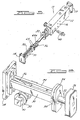
- the extrusion shape of the body member 12 permits the use of a single T-slot 19 or multiple T-slots located in the body member 12 or the body member 112 to facilitate mounting thereof, see Figure 18.
- This T-slot type mounting can replace or augment the technique of bolting and/or doweling the clamp to its work station.
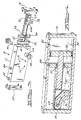
- the piston 230 includes a first and second seal plate 233, 235 which surround a first and second piston plate 237, 239 and a first seal anti-extrusion plate 241.
- a first and second piston seal 243, 245 surround the outer edge or periphery of the piston 232 and are adjacent to the seal anti-extrusion plate 241.
- the piston 232 is arranged on the reduced radius portion 231 of the piston rod 232 and is secured by any known securing means 247 in contact with a shoulder of the reduced portion of the piston rod 231 and connected by the securing means 247 on the end opposite of the shoulder.
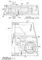
- a drive plate 236 generally having a body 207 and an appendage 209 that extends therefrom is also a part of the internal assembly.
- the appendage 209 has a predetermined angle from a center line of the drive plate body 207.
- the appendage 209 also includes a shoulder portion 211 that creates a stop for the power clamp 210.
- the drive plate 236 has an orifice 213 through its body portion that mates with a drive shaft 240 male member for the power clamp 210.
- a channel 215 is located in the appendage 209 of the drive plate 236 and is arranged such that the roller pin 201 is placed through the channel 215 and allows for the drive plate 236 to be connected to the clevis 264 which is located within the track assembly 259. It should also be noted that a toggle link may also be used according to this second alternate embodiment.
- the design of the clamp 210 can be changed such that the angle of the channel through the appendage 209 of the drive plate 236 creates a quicker movement towards the positive stop of the power clamp 210 thus reducing the axial movement of the piston 230 within the piston chamber 280 and reducing the forces necessary to hold the clamp or increase the forces necessary to hold the clamp in a closed position.
- the roller bearings 203 and clevis 264 have axial movement within the track assembly 259 due to the forces being translated by the piston rod 232.
Landscapes
- Engineering & Computer Science (AREA)
- Mechanical Engineering (AREA)
- Jigs For Machine Tools (AREA)
Applications Claiming Priority (4)
| Application Number | Priority Date | Filing Date | Title |
|---|---|---|---|
| US240738 | 1981-03-05 | ||
| US24073800P | 2000-10-16 | 2000-10-16 | |
| US956231 | 2001-09-19 | ||
| US09/956,231 US6655673B2 (en) | 2000-10-16 | 2001-09-19 | Power clamp mechanism |
Publications (2)
| Publication Number | Publication Date |
|---|---|
| EP1201369A2 true EP1201369A2 (fr) | 2002-05-02 |
| EP1201369A3 EP1201369A3 (fr) | 2003-12-17 |
Family
ID=26933661
Family Applications (1)
| Application Number | Title | Priority Date | Filing Date |
|---|---|---|---|
| EP01308690A Withdrawn EP1201369A3 (fr) | 2000-10-16 | 2001-10-12 | Mécanisme de serrage motorisé |
Country Status (6)
| Country | Link |
|---|---|
| US (1) | US6655673B2 (fr) |
| EP (1) | EP1201369A3 (fr) |
| CN (1) | CN1362312A (fr) |
| AU (1) | AU7824301A (fr) |
| CA (1) | CA2358160A1 (fr) |
| MX (1) | MXPA01010448A (fr) |
Cited By (7)
| Publication number | Priority date | Publication date | Assignee | Title |
|---|---|---|---|---|
| EP1264663A3 (fr) * | 2001-06-05 | 2004-05-12 | PHD, Inc. | Dispositif de serrage |
| EP1563957A1 (fr) * | 2004-02-13 | 2005-08-17 | DE-STA-CO Metallerzeugnisse GmbH | Dispositif d'entraínement |
| WO2007131499A1 (fr) | 2006-05-17 | 2007-11-22 | De-Sta-Co Europe Gmbh | Dispositif de serrage |
| US8136803B2 (en) | 2007-01-15 | 2012-03-20 | Phd, Inc. | Armover clamp assembly |
| DE102010051573A1 (de) | 2010-11-18 | 2012-05-24 | De-Sta-Co Europe Gmbh | Spannvorrichtung |
| CN104091586A (zh) * | 2014-07-15 | 2014-10-08 | 齐鲁师范学院 | 快速拆装式乐谱架 |
| CN112109017A (zh) * | 2020-09-27 | 2020-12-22 | 山东工业职业学院 | 一种工件夹持方法 |
Families Citing this family (17)
| Publication number | Priority date | Publication date | Assignee | Title |
|---|---|---|---|---|
| US7021687B2 (en) | 1998-08-04 | 2006-04-04 | Phd, Inc. | Clamp assembly |
| US7000911B2 (en) * | 2001-06-22 | 2006-02-21 | Delaware Capital Formation, Inc. | Motor pack for automated machinery |
| US7815176B2 (en) * | 2003-09-11 | 2010-10-19 | Phd, Inc. | Lock mechanism for pin clamp assembly |
| US7516948B2 (en) | 2004-04-02 | 2009-04-14 | Phd, Inc. | Pin clamp accessories |
| US20070042632A1 (en) * | 2005-08-19 | 2007-02-22 | Parag Patwardhan | Pin clamp assembly |
| ES2707249T3 (es) | 2007-06-19 | 2019-04-03 | Phd Inc | Conjunto de abrazadera de pasador |
| USD659789S1 (en) * | 2011-01-03 | 2012-05-15 | Trevino Iii Fermin | Gun trigger lock |
| DE102012006867B3 (de) * | 2012-04-04 | 2013-03-28 | Tünkers Maschinenbau Gmbh | Kniehebelspannvorrichtung, insbesondere zur Verwendung im Karosseriebau der Kfz-Industrie |
| CN107051604B (zh) * | 2012-08-30 | 2019-07-05 | 生命技术公司 | 竖直夹具装置 |
| CN104148961B (zh) * | 2014-09-10 | 2016-09-21 | 上海中船三井造船柴油机有限公司 | 一种可消除装夹间隙的工件支撑装置 |
| DE102016121968B4 (de) | 2015-11-20 | 2022-03-17 | Springer Gmbh | Vorrichtung zum Greifen und/oder Spannen eines Werkstückes mit Schubachse und Schwenkwelle auf einer Wirklinie mit einer Kolbenstange |
| CN107690905B (zh) * | 2017-10-29 | 2019-09-06 | 潍坊学院 | 农业用移栽机夹苗机构气缸定位结构 |
| CN107825194A (zh) * | 2017-12-15 | 2018-03-23 | 浙江青霄科技股份有限公司 | 一种气动夹具 |
| CN108544228A (zh) * | 2018-06-15 | 2018-09-18 | 广东统机器人智能股份有限公司 | 一种滚轴自动装配机 |
| EP4208313A4 (fr) | 2020-09-02 | 2025-01-15 | Versabuilt, Inc. | Étau |
| CN117817074B (zh) * | 2024-03-04 | 2024-05-07 | 常州市汇淼机电科技工程有限公司 | 一种高强度钢塔筒用全自动焊接设备 |
| CN119839794B (zh) * | 2025-02-08 | 2025-10-10 | 博众精工科技股份有限公司 | 夹具机构 |
Family Cites Families (18)
| Publication number | Priority date | Publication date | Assignee | Title |
|---|---|---|---|---|
| US4570914A (en) | 1982-03-26 | 1986-02-18 | Blatt Leland F | Power operated clamp |
| US4396183A (en) | 1982-05-10 | 1983-08-02 | Lymburner Robert K | Power actuated clamp |
| US5118088A (en) * | 1990-04-30 | 1992-06-02 | Btm Corporation | Power clamp |
| US5171001A (en) * | 1987-05-27 | 1992-12-15 | Btm Corporation | Sealed power clamp |
| US4778163A (en) | 1987-07-31 | 1988-10-18 | Spear Larry R | Air actuated clamp |
| US5490663A (en) * | 1992-08-07 | 1996-02-13 | United Technologies Automotive, Inc. | Slide actuated holding clamp |
| US5257774A (en) * | 1992-11-22 | 1993-11-02 | Delaware Capital Formation, Inc. | Power actuated pull clamp |
| US5460358A (en) | 1993-11-29 | 1995-10-24 | Sendoykas; Jack J. | Power clamp |
| US5975605A (en) | 1994-11-14 | 1999-11-02 | Kot; Norbert J | Enclosed clamping or gripping device with accessible load controlling spring |
| US5884903A (en) * | 1995-10-30 | 1999-03-23 | Btm Corporation | Powered clamp and gauging apparatus |
| US5687961A (en) | 1995-11-30 | 1997-11-18 | Aladdin Engineering & Manufacturing, Inc. | Fluid operated clamp including integral frame and slide member support |
| US5762325A (en) * | 1996-01-29 | 1998-06-09 | Isi Norgren Inc. | Power actuated gripper |
| JP3749315B2 (ja) * | 1996-09-06 | 2006-02-22 | Smc株式会社 | チャック装置 |
| JP4099729B2 (ja) | 1997-03-05 | 2008-06-11 | Smc株式会社 | シリンダ装置 |
| FR2769255B1 (fr) | 1997-10-08 | 1999-12-03 | Genus Technologie Ind | Dispositif de maintien, de positionnement, ou de serrage |
| US6003850A (en) | 1998-04-28 | 1999-12-21 | Isi Norgren, Inc. | Electric power operated clamp |
| US6059277A (en) | 1998-05-05 | 2000-05-09 | Btm Corporation | Retracting power clamp |
| US6070864A (en) | 1998-11-03 | 2000-06-06 | Isi Norgren, Inc. | Electric power operated positioning apparatus |
-
2001
- 2001-09-19 US US09/956,231 patent/US6655673B2/en not_active Expired - Fee Related
- 2001-10-01 CA CA002358160A patent/CA2358160A1/fr not_active Abandoned
- 2001-10-05 AU AU78243/01A patent/AU7824301A/en not_active Abandoned
- 2001-10-12 EP EP01308690A patent/EP1201369A3/fr not_active Withdrawn
- 2001-10-14 CN CN01138405A patent/CN1362312A/zh active Pending
- 2001-10-16 MX MXPA01010448A patent/MXPA01010448A/es unknown
Cited By (9)
| Publication number | Priority date | Publication date | Assignee | Title |
|---|---|---|---|---|
| EP1264663A3 (fr) * | 2001-06-05 | 2004-05-12 | PHD, Inc. | Dispositif de serrage |
| EP1563957A1 (fr) * | 2004-02-13 | 2005-08-17 | DE-STA-CO Metallerzeugnisse GmbH | Dispositif d'entraínement |
| WO2007131499A1 (fr) | 2006-05-17 | 2007-11-22 | De-Sta-Co Europe Gmbh | Dispositif de serrage |
| US8162300B2 (en) | 2006-05-17 | 2012-04-24 | De-Sta-Co Europe Gmbh | Clamping device |
| US8136803B2 (en) | 2007-01-15 | 2012-03-20 | Phd, Inc. | Armover clamp assembly |
| DE102010051573A1 (de) | 2010-11-18 | 2012-05-24 | De-Sta-Co Europe Gmbh | Spannvorrichtung |
| CN104091586A (zh) * | 2014-07-15 | 2014-10-08 | 齐鲁师范学院 | 快速拆装式乐谱架 |
| CN112109017A (zh) * | 2020-09-27 | 2020-12-22 | 山东工业职业学院 | 一种工件夹持方法 |
| CN112109017B (zh) * | 2020-09-27 | 2021-11-23 | 台州市路桥凯通管业有限公司 | 一种工件夹持方法 |
Also Published As
| Publication number | Publication date |
|---|---|
| CN1362312A (zh) | 2002-08-07 |
| US6655673B2 (en) | 2003-12-02 |
| MXPA01010448A (es) | 2004-04-05 |
| CA2358160A1 (fr) | 2002-04-16 |
| EP1201369A3 (fr) | 2003-12-17 |
| AU7824301A (en) | 2002-05-02 |
| US20020043751A1 (en) | 2002-04-18 |
Similar Documents
| Publication | Publication Date | Title |
|---|---|---|
| US6655673B2 (en) | Power clamp mechanism | |
| AU716861B2 (en) | Force multiplying apparatus | |
| US6199847B1 (en) | Cylinder apparatus | |
| EP0115431B1 (fr) | Mécanisme de verrouillage pour des moules d'une presse de vulcanisation de pneumatiques | |
| US5061166A (en) | Extruder head | |
| US5174585A (en) | Adjustable fastening device | |
| US4459909A (en) | Mold supporting arrangement in a press | |
| CN110216192B (zh) | 一种快速换模的冲压装置 | |
| EP1025951B1 (fr) | Dispositif de serrage | |
| CN215462269U (zh) | 压滤机及其改装套件 | |
| EP1016509A2 (fr) | Dispositif fileté pour le positionnement d'une structure soumise à des charges importantes | |
| US4511127A (en) | Hydraulic-mechanical clamping device | |
| EP1118424A1 (fr) | Dispositif de serrage | |
| US4509910A (en) | Column clamping assembly | |
| DE19609568A1 (de) | Druckausgleichsvorrichtung | |
| RU2448800C2 (ru) | Устройство для формирования дна банок | |
| US20110086123A1 (en) | Method and device for mounting forms | |
| IE43153B1 (en) | Presses | |
| US3834217A (en) | Pivotal clamping mechanism for die sets | |
| JP2003139105A (ja) | 新パワー・クランプ機構 | |
| WO2000072992A1 (fr) | Procede et appareil d'elaboration d'article modele | |
| USRE32704E (en) | Hydraulic-mechanical clamping device | |
| DE20216543U1 (de) | Abdichtvorrichtung | |
| EP0659501B1 (fr) | Machine à forger | |
| EP1728593B1 (fr) | Étau pneumatique avec dispositif de commande et de sécurité intégré |
Legal Events
| Date | Code | Title | Description |
|---|---|---|---|
| PUAI | Public reference made under article 153(3) epc to a published international application that has entered the european phase |
Free format text: ORIGINAL CODE: 0009012 |
|
| AK | Designated contracting states |
Kind code of ref document: A2 Designated state(s): AT BE CH CY DE DK ES FI FR GB GR IE IT LI LU MC NL PT SE TR |
|
| AX | Request for extension of the european patent |
Free format text: AL;LT;LV;MK;RO;SI |
|
| RAP1 | Party data changed (applicant data changed or rights of an application transferred) |
Owner name: DELAWARE CAPITAL FORMATION, INC. |
|
| PUAL | Search report despatched |
Free format text: ORIGINAL CODE: 0009013 |
|
| AK | Designated contracting states |
Kind code of ref document: A3 Designated state(s): AT BE CH CY DE DK ES FI FR GB GR IE IT LI LU MC NL PT SE TR |
|
| AX | Request for extension of the european patent |
Extension state: AL LT LV MK RO SI |
|
| RIC1 | Information provided on ipc code assigned before grant |
Ipc: 7B 25B 5/12 B Ipc: 7B 25B 5/08 A |
|
| AKX | Designation fees paid | ||
| REG | Reference to a national code |
Ref country code: DE Ref legal event code: 8566 |
|
| STAA | Information on the status of an ep patent application or granted ep patent |
Free format text: STATUS: THE APPLICATION IS DEEMED TO BE WITHDRAWN |
|
| 18D | Application deemed to be withdrawn |
Effective date: 20040504 |