EP1201414A2 - Procédé de fabrication d'un flanc de pneumatique - Google Patents
Procédé de fabrication d'un flanc de pneumatique Download PDFInfo
- Publication number
- EP1201414A2 EP1201414A2 EP01125788A EP01125788A EP1201414A2 EP 1201414 A2 EP1201414 A2 EP 1201414A2 EP 01125788 A EP01125788 A EP 01125788A EP 01125788 A EP01125788 A EP 01125788A EP 1201414 A2 EP1201414 A2 EP 1201414A2
- Authority
- EP
- European Patent Office
- Prior art keywords
- rubber
- tape
- sidewall
- tire
- unvulcanized
- Prior art date
- Legal status (The legal status is an assumption and is not a legal conclusion. Google has not performed a legal analysis and makes no representation as to the accuracy of the status listed.)
- Granted
Links
Images




Classifications
-
- B—PERFORMING OPERATIONS; TRANSPORTING
- B29—WORKING OF PLASTICS; WORKING OF SUBSTANCES IN A PLASTIC STATE IN GENERAL
- B29D—PRODUCING PARTICULAR ARTICLES FROM PLASTICS OR FROM SUBSTANCES IN A PLASTIC STATE
- B29D30/00—Producing pneumatic or solid tyres or parts thereof
- B29D30/06—Pneumatic tyres or parts thereof (e.g. produced by casting, moulding, compression moulding, injection moulding, centrifugal casting)
- B29D30/08—Building tyres
-
- B—PERFORMING OPERATIONS; TRANSPORTING
- B60—VEHICLES IN GENERAL
- B60C—VEHICLE TYRES; TYRE INFLATION; TYRE CHANGING; CONNECTING VALVES TO INFLATABLE ELASTIC BODIES IN GENERAL; DEVICES OR ARRANGEMENTS RELATED TO TYRES
- B60C13/00—Tyre sidewalls; Protecting, decorating, marking, or the like, thereof
- B60C13/04—Tyre sidewalls; Protecting, decorating, marking, or the like, thereof having annular inlays or covers, e.g. white sidewalls
-
- B—PERFORMING OPERATIONS; TRANSPORTING
- B29—WORKING OF PLASTICS; WORKING OF SUBSTANCES IN A PLASTIC STATE IN GENERAL
- B29C—SHAPING OR JOINING OF PLASTICS; SHAPING OF MATERIAL IN A PLASTIC STATE, NOT OTHERWISE PROVIDED FOR; AFTER-TREATMENT OF THE SHAPED PRODUCTS, e.g. REPAIRING
- B29C48/00—Extrusion moulding, i.e. expressing the moulding material through a die or nozzle which imparts the desired form; Apparatus therefor
- B29C48/03—Extrusion moulding, i.e. expressing the moulding material through a die or nozzle which imparts the desired form; Apparatus therefor characterised by the shape of the extruded material at extrusion
- B29C48/07—Flat, e.g. panels
-
- B—PERFORMING OPERATIONS; TRANSPORTING
- B29—WORKING OF PLASTICS; WORKING OF SUBSTANCES IN A PLASTIC STATE IN GENERAL
- B29D—PRODUCING PARTICULAR ARTICLES FROM PLASTICS OR FROM SUBSTANCES IN A PLASTIC STATE
- B29D30/00—Producing pneumatic or solid tyres or parts thereof
- B29D30/06—Pneumatic tyres or parts thereof (e.g. produced by casting, moulding, compression moulding, injection moulding, centrifugal casting)
- B29D30/72—Side-walls
-
- B—PERFORMING OPERATIONS; TRANSPORTING
- B29—WORKING OF PLASTICS; WORKING OF SUBSTANCES IN A PLASTIC STATE IN GENERAL
- B29C—SHAPING OR JOINING OF PLASTICS; SHAPING OF MATERIAL IN A PLASTIC STATE, NOT OTHERWISE PROVIDED FOR; AFTER-TREATMENT OF THE SHAPED PRODUCTS, e.g. REPAIRING
- B29C48/00—Extrusion moulding, i.e. expressing the moulding material through a die or nozzle which imparts the desired form; Apparatus therefor
- B29C48/03—Extrusion moulding, i.e. expressing the moulding material through a die or nozzle which imparts the desired form; Apparatus therefor characterised by the shape of the extruded material at extrusion
- B29C48/12—Articles with an irregular circumference when viewed in cross-section, e.g. window profiles
-
- B—PERFORMING OPERATIONS; TRANSPORTING
- B29—WORKING OF PLASTICS; WORKING OF SUBSTANCES IN A PLASTIC STATE IN GENERAL
- B29C—SHAPING OR JOINING OF PLASTICS; SHAPING OF MATERIAL IN A PLASTIC STATE, NOT OTHERWISE PROVIDED FOR; AFTER-TREATMENT OF THE SHAPED PRODUCTS, e.g. REPAIRING
- B29C48/00—Extrusion moulding, i.e. expressing the moulding material through a die or nozzle which imparts the desired form; Apparatus therefor
- B29C48/25—Component parts, details or accessories; Auxiliary operations
- B29C48/30—Extrusion nozzles or dies
- B29C48/32—Extrusion nozzles or dies with annular openings, e.g. for forming tubular articles
- B29C48/33—Extrusion nozzles or dies with annular openings, e.g. for forming tubular articles with parts rotatable relative to each other
-
- Y—GENERAL TAGGING OF NEW TECHNOLOGICAL DEVELOPMENTS; GENERAL TAGGING OF CROSS-SECTIONAL TECHNOLOGIES SPANNING OVER SEVERAL SECTIONS OF THE IPC; TECHNICAL SUBJECTS COVERED BY FORMER USPC CROSS-REFERENCE ART COLLECTIONS [XRACs] AND DIGESTS
- Y10—TECHNICAL SUBJECTS COVERED BY FORMER USPC
- Y10T—TECHNICAL SUBJECTS COVERED BY FORMER US CLASSIFICATION
- Y10T152/00—Resilient tires and wheels
- Y10T152/10—Tires, resilient
- Y10T152/10495—Pneumatic tire or inner tube
- Y10T152/10513—Tire reinforcement material characterized by short length fibers or the like
-
- Y—GENERAL TAGGING OF NEW TECHNOLOGICAL DEVELOPMENTS; GENERAL TAGGING OF CROSS-SECTIONAL TECHNOLOGIES SPANNING OVER SEVERAL SECTIONS OF THE IPC; TECHNICAL SUBJECTS COVERED BY FORMER USPC CROSS-REFERENCE ART COLLECTIONS [XRACs] AND DIGESTS
- Y10—TECHNICAL SUBJECTS COVERED BY FORMER USPC
- Y10T—TECHNICAL SUBJECTS COVERED BY FORMER US CLASSIFICATION
- Y10T152/00—Resilient tires and wheels
- Y10T152/10—Tires, resilient
- Y10T152/10495—Pneumatic tire or inner tube
- Y10T152/10819—Characterized by the structure of the bead portion of the tire
- Y10T152/10828—Chafer or sealing strips
-
- Y—GENERAL TAGGING OF NEW TECHNOLOGICAL DEVELOPMENTS; GENERAL TAGGING OF CROSS-SECTIONAL TECHNOLOGIES SPANNING OVER SEVERAL SECTIONS OF THE IPC; TECHNICAL SUBJECTS COVERED BY FORMER USPC CROSS-REFERENCE ART COLLECTIONS [XRACs] AND DIGESTS
- Y10—TECHNICAL SUBJECTS COVERED BY FORMER USPC
- Y10T—TECHNICAL SUBJECTS COVERED BY FORMER US CLASSIFICATION
- Y10T152/00—Resilient tires and wheels
- Y10T152/10—Tires, resilient
- Y10T152/10495—Pneumatic tire or inner tube
- Y10T152/10855—Characterized by the carcass, carcass material, or physical arrangement of the carcass materials
- Y10T152/10864—Sidewall stiffening or reinforcing means other than main carcass plies or foldups thereof about beads
Definitions
- the present invention relates to a method of manufacturing a pneumatic tire whose rubber components are formed by winding a unvulcanized rubber tape.
- unvulcanized rubber tires are made of unvulcanized rubber components having various shapes and sizes.
- the unvulcanized rubber components are formed by extruders, the number and sizes of the extruders are depend on the maximum size and the number of the kinds of the rubber components. Usually, at least several extruders which are relatively large-sized are required.
- a primary object of the present invention is to provide a method of manufacturing a pneumatic tire, by which it is possible to establish a flexible manufacturing system and to decrease the plant size, whereas another object of the present invention is to increase the number of rubber components which are made by winding au unvulcanized rubber tape. Still another object of the present invention is to decrease the number of unvulcanized rubber tapes used in a tire.
- a method of manufacturing a pneumatic tire comprises assembling unvulcanized rubber components to make a green tire, vulcanizing the green tire, and winding an unvulcanized rubber tape so that the windings collectively have a predetermined cross sectional shape for at least one of the unvulcanized rubber components to thereby make said at least one of the unvulcanized rubber components.
- tire components are formed by winding a long unvulcanized rubber tape T.
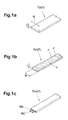
- the unvulcanized rubber tape T means a pure rubber tape Tp made of unvulcanized rubber only, a fiber containing rubber tape Trf made of unvulcanized rubber with short fibers mixed therein, and a cord containing rubber tape Trc made of unvulcanized rubber in which one or more cords are embedded along the length of the tape.
- Figs.1a, 1b and 1c show examples of the pure rubber tape Tp, fiber containing rubber tape Trf and cord containing rubber tape Trc, respectively.
- the thickness (T) of the unvulcanized rubber tape T may be set in a range of from 0.3 to 2.5 mm, preferably in a range of from 0.5 to 2.0 mm.
- the width W of the unvulcanized rubber tape T may be set in a range of from 5 to 50 mm preferably in a range of from 10 to 25 mm.
- the present invention can be applied to various pneumat ic tires, e.g. passenger car tires, light truck tires, motorcycle tires, heavy duty tires and the like. However, for the sake of convenience, the following descriptions are made based on passenger car radial tires having a low aspect ratio.
- pneumatic tire 1 comprises a tread portion 2, a pair of sidewall portions 3, a pair of bead portions 4 each with a bead core 5 therein, a carcass 6 extending between the bead portions 4, and a tread reinforcing belt disposed radially outside the carcass 6 in the tread portion 2.
- the carcass 6 comprises at least one ply 6A of cords arranged radially at an angle of from 75 to 90 degrees with respect to the tire equator C, extending between the bead portions 4 through the tread portion 2 and sidewall portions 3, and turned up around the bead core 5 in each bead portion 4 from the inside to the outside of the tire so as to form a pair of turnups 6b and the main 6a therebetween.
- organic fiber cords e.g. polyester, nylon, rayon, aramid and the like or steel cords are used.
- the exemplary carcass 6 shown in the drawings is composed of a single ply 6A of organic fiber cords arranged radially at 90 degrees, and the carcass ply turnups 6b extend radially outwardly beyond the maximum section width point of the carcass main 6b.
- the tread reinforcing belt comprises a breaker 7 and a optional band disposed on the radially outside of the breaker 7.
- the breaker 7 is disposed on the crown portion of the carcass 6 and comprises at least two cross plies 7A and 7B of cords laid parallel with each other at an angle of from 10 to 45 degrees with respect to the tire equator.
- steel cords and high-modulus organic cords such as aramid fiber cords can be used.
- the band is disposed on the radially outside of the breaker 7 and made of cord(s) laid at almost zero angle or a small angle with respect to the circumferential direction of the tire.
- the band is formed by spirally winding at least one organic fiber cord, e.g. nylon and the like, at an angle of not more than 5 degrees with respect to the tire equator.
- a rubber tape Trc in which band cords are embedded along the length thereof as shown in Fig.1c is preferably used.
- the exemplary belt shown in the drawings is composed of a breaker 7 made up of two cross plies of steel cords.
- a pneumatic tire is compose of various rubber components.
- a tread rubber Gt is disposed radially outside the belt.
- a sidewall rubber Gs is disposed axially outside the carcass 6 defining a part of the outer surface of the tire.
- a clinch rubber Gbc is disposed along the axially outer surface and bottom surface of the bead portion, and a bead apex rubber Gba is further disposed on the radially outside of the bead core 5 and extends radially outwardly therefrom while tapering towards its radially outer end.
- an inner liner rubber Gil made of an air-impermeable rubber compound may disposed to cover the inner surface of the tire air-tightly.
- the bead apex rubber Gba is made of a hard rubber compound and disposed between the carcass main 6a and turnup 6b and terminates on the radially inside of the radially outer end of the turnup 6b.
- At least the sidewall rubber Gs is formed by winding a long unvulcanized rubber tape T.
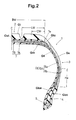
- Fig.2 shows a radial tire for passenger cars in its normally inflated unloaded state.
- the normally inflated unloaded state is such that the tire is mounted on a standard wheel rim and inflated to a standard inner pressure but loaded with no tire load.
- the standard rim is the "standard rim” specified in JATMA, the “Measuring Rim” in ETRTO, the “Design Rim” in TRA or the like.
- the standard pressure is the “maximum air pressure” in JATMA, the “Inflation Pressure” in ETRTO, the maximum pressure given in the "Tire Load Limits at Various Cold Inflation Pressures” table in TRA or the like. In case of passenger car tires, however, 180 kPa is used as the standard pressure.
- the standard load is the "maximum load capacity" in JATMA, the “Load Capacity” in ETRTO, the maximum value given in the above-mentioned table in TRA or the like.
- a thin under tread rubber Gut is disposed between the belt 7 and the tread rubber Gt to improve the adhesion between the belt 7 and the tread rubber Gt.
- a cushion rubber Gtc is disposed between the axially outer edges 7e of the belt 7 and the carcass 6 in order to mitigate a stress on the belt edge.
- the axial overlap width CW of the cushion rubber Gtc and the belt 7 is set in a range of from 0.05 to 0.25 times preferably 0.07 to 0.2 times the axial width BW of the belt 7.
- the cushion rubber Gtc tapers from its middle point towards each side thereof.
- each of the sidewall por tions 3 is provided between the carcass 6 and the inner liner rubber Gil with an insulation rubber Gin to prevent a separation of the inner liner rubber Gil from the carcass 6.
- the insulation rubber Gin extends at least between a position near the axially outer end of the belt 7 and a position radially inwards of the maximum section width point of the carcass main 6a.
- the insulation rubber Gin overlaps with the belt 7 by an axial width LW in a range of from 0.2 to 0.5 times preferably 0.2 to 0.4 times the axial width BW of the belt 7.
- the radially inner end of the insulation rubber Gin is spaced radially inwardly from the maximum section width point of the carcass main by a radial distance Ha in a range of not less than 0.1 times preferably 0.3 to 0.4 times the tire section height.
- the radially inner end of the insulation rubber Gin is positioned radially inside the radially outer end of the bead apex rubber Gba.
- the above-mentioned clinch rubber Gbc comprises a base part extending along the bottom face of the bead portion 4, and an axially outer part and an axially inner part extending along the axially outer surface and axially inner surface of the bead portion 4, respectively.
- the above-mentioned sidewal 1 rubber Gs is spliced with the tread rubber Gt and the axially outer part of the clinch rubber Gbc.
- the sidewall rubber Gs, insulation rubber Gin and cushion rubber Gtc are formed by winding a pure rubber tape Tp1, namely, these are made of the identical rubber compound.
- the clinch rubber Gbc is formed by winding a pure rubber tape Tp2 made of a different rubber compound.
- the inner liner rubber Gil is formed by winding a pure rubber tape Tp3 made of a different air- impermeable rubber compound.
- a butyl-base rubber compound is used for the unvulcanized rubber tape Tp3, which includes at least 50 parts by weight of butyl rubber or a derivative thereof with respect to 100 parts by weight of the base rubber.
- halogenated butyl rubber such as chlorinated butyl rubber, brominated butyl rubber and the like is used.
- the sidewall rubber Gs, cushion rubber Gtc and insulation rubber Gin are disposed in regions where deformation is relatively large, the rubber components are subjected to mechanical fatigue. Accordingly, it is very important to prevent separation failure between the windings of the rubber tape Tp1 and cracks on the tire outer surface along the boundaries therebetween.
- the sidewall rubber Gs should be superior in the cut resistance, weatherproof, flexibility and the like.
- the clinch rubber Gbc is pressed and rubs against the wheel rim and it is necessary to provide the bead portion with rigidity.
- a non-butyl-based rubber compound superior in adhesion and elasticity which includes 40 to 100 parts by weight of a low viscosity polybutadiene rubber and at least 2.5, preferably at least 2.7, more preferably 3.0 to 4.0 parts by weight of age resistor with respect to 100 parts by weight of the rubber component thereof.
- the Mooney viscosity of the low viscosity polybutadiene rubber is set in a range of not more than 40, preferably from 28 to 38, more preferably 25 to 35 ⁇ ML(1+4) @100deg.C ⁇ .
- the age resistor for example,
- the sidewall rubber Gs, cushion rubber Gtc and insulation rubber Gin namely, the rubber tape Tp1 when vulcanized have a 100 % modulus of from 0.5 to 2.5 MPa preferably 0.5 to 2.0 MPa more preferably 0.7 to 2.0 MPa, and a JIS type-A-durometer hardness of not more than 65 degrees preferably 40 to 65 degrees more preferably 50 to 62 degrees.
- the rigidity becomes insufficient for the sidewall portion 3 and it is difficult to maintain the steering stability. If the 100 % modulus is more than 2.5 MPa and/or the JIS type-A-durometer hardness is more than 65 degrees, then it is difficult for the cushion rubber Gtc to mitigate the stress on the belt edge, and it is difficult to provide necessary elasticity for the sidewall rubber Gs.
- the following table shows an example of the rubber compound of the rubber tape Tp1. (parts by weight ) Natural rubber 40 Low viscosity polybutadiene rubber 60 FEF 50 Aromatic oil 5 Age resistor 3 Wax 1.5 Stearic acid 2.5 Zinc oxide 3.0 Vulcanization accelerator 1.0 Sulfur 1.5 JIS type-A-durometer hardness 55 100 %modulus 1.1 MPa
- JIS type-A-durometer hardness is measured according to the Japanese Industrial Standard K6253.
- Mooney viscosity is measured according to the Japanese Industrial Standard K6300.
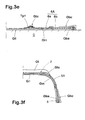
- the above-mentioned pneumatic tire 1 can be made as shown in Figs.3a to 3g.
- the above-mentioned tape Tp2 is wound on a cylindrical tire building drum D to make the clinch rubber Gbc on each side of the drum center while leaving a space therebetween.
- the tape Tp3 is wound on the cylindrical tire building drum D across the space between the windings of the tape Tp2.
- the inner liner rubber Gil is somewhat overlapped with the clinch rubber Gbc.
- the tape Tp1 is wound on the inner liner rubber Gil.
- a wide raw strip of rubberized carcass cords is applied thereon. Further, the bead core 5 and raw bead apex rubber Gba are placed in each of the corresponding positions on the wound carcass strip.
- the rubber tape Tp1 is wound on the carcass strip into a substantially triangular sectional shape.
- the rubber tape Tp1 is used again.
- the rubber tape Tp1 is wound on the axially outer face of the carcass 6.
- the rubber tape Tp1 is used one again.
- a green tire is made.
- the green tire is put in a mold and vulcanized.
- the above-mentioned tread rubber and belt assembly may be made as follows.
- a raw strip of rubberized breaker cords is applied to or wound on a profiled belt drum to make the breaker 7.
- the belt includes a band, a rubber tape Trc in which one or more band cords are embedded along the length thereof is spirally wound.
- an unvulcanized rubber tape T is wound on the belt to make the under tread rubber Gtu (not shown), and another unvulcanized rubber tape T is wound thereon to make the tread rubber Gt.
- a natural-rubber-base rubber compound superior in adhesion is used for the unvulcanized rubber tape T of the under tread rubber Gut.
- a rubber compound superior in the wear resistance, heat generation and grip performance is used for the unvulcanized rubber tape T ( Tp or Trf) of the tread rubber Gt.
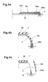
- the sidewall rubber Gs can be made by winding an unvulcanized rubber tape T on the toroidal-shaped carcass as illustrated above. But, as shown in Figs.4a and 4b, it is also possible to make the sidewall rubber Gs by winding an unvulcanized rubber tape T on the carcass in a cylindrical shape, and thereafter the tape T is wound, the carcass, sidewall rubber, etc. are changed into a toroidal shape.
- Fig.4c it is possible to form the sidewall rubber Gs on another drum by winding an unvulcanized rubber tape T together with the clinch rubber Gbc, and then apply the assembly of the sidewall rubber Gs and clinch rubber Gbc to the toroidal shaped carcass.
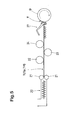
- Fig.5 schematically shows an apparatus for maki ng and winding an unvulcanized rubber tape T, which comprises an extruder 20 including a screw and a die, a pair of rollers 21 disposed near the outlet of the extruder's die to adjusting the thickness of the rubber tape T, a plurality of cooling rollers 22, 23 and 24 for cooling the extruded rubber tape T, a tape applicator 27 which can traverse the building drum D, and rollers for guiding and conveying the rubber tape to the applicator 27.
- the material rubber compound fed to the extruder is mixed by the screw and extruded from the die into a flat sectional shape.
- the extruded unvulcanized rubber is rolled by the rollers 21.
- the thickness of the rubber tape T is adjusted to the target thickness.
- the rubber tape T is fed to the applicator 27 through cooling rollers and guide rollers.
- the rubber tape T is wound on the building drum D by rotating the building drum D and traversing the tape applicator 27 to give a predetermined sectional shape to the windings.
- the extruding speed, rollers' gap, drum speed, applicator speed, applicator position and the like are controlled by a computer according to stored programs and outputs of various sensors for the tape thickness, various positions, various speeds, temperature, etc. If necessary, a tape accumulator may be provided between the extruder and applicator.
- the sidewall rubber Gs, insulation rubber Gin and cushion rubber Gtc can be made by winding the same rubber tape Tp1 and the resultant tire can display its performance equal to a tire made by the conventional method.
- a solution therefor is to use a fiber containing rubber tape Trf of which short fibers have a variable degree of orientation.
- the fiber containing rubber tape Trf is made by extruding the fiber mixed rubber compound and rolling the extruded compound.
- the short fibers in the rubber tape Trf are oriented in the extruding direction or the longitudinal direction of the tape through these process. It is possible to control the degree of orientation by changing the thickness of the rubber tape Trf.
- the thinner rubber tape has a higher degree of orientation.
- the fiber containing rubber tape Trf having a variable degree of orientation includes a thin tape and a thick tape.
- the thin tape and thick tape may be discontinuous. But, in this example, these are continuous.
- non-metallic fibers are used for the short fibers F.
- organic fibers e.g. nylon, polyester, aramid, rayon, vinylon, cotton, cellulosic resin, crystalline polybutadiene and the like
- inorganic fibers e.g. glass fiber, carbon fiber, boron fiber and the like may be used alone or in combination as far as a sufficient adhesion to the rubber can be obtained.
- the average length of the short fibers F is set in a range of from 0.2 to 5 preferably 1.0 to 4.0 millimeters, and the average diameter thereof is in a range of from 10 to 100 preferably 50 to 80 micrometers.
- nylon 66 fibers having an average length of 3.5 mm and an average diameter of 70 to 80 micrometers are used.
- the content of the short fibers F is set in a range of from 10 to 30 preferably 15 to 25 parts by weight with respect to 100 parts by weight of the rubber component of the compound.
- the rubber component there is used diene rubber such as natural rubber, isoprene rubber, styrene butadiene rubber, butadiene rubber, chloroprene rubber, acrylonitrile butadiene rubber and the like, alone or in combination.
- the thickness (t) of the fiber containing rubber tape Trf is set in a range of from 0.3 to 2.5 mm preferably 0.5 to 2.0 mm as mentioned above.
- the ratio (t1/t2) of the thickness t1 of the thin tape to the thickness t2 of the thick tape is set in a range of from 0.15 to 0.80 preferably 0.20 to 0.75 more preferably 0.20 to 0.70.
- the width W of the rubber tape Trf may be set in a range of from 5 to 50 mm preferably 10 to 25 mm.
- part A1 is formed by winding a thin tape Trf1 and part A2 is formed by winding a thick tape Trf2.
- the part A1 may have a higher rigidity than the part A2.
- the sidewall rubber Gs is formed by winding the fiber containing unvulcanized rubber tape Trf.
- the short fibers F in the rubber tape Trf are oriented almost parallel with the longitudinal direction of the tape, the short fibers F are oriented substantially in the tire circumferential direction.
- a middle part of the sidewall rubber Gs where the bending deformation during running is largest, is formed by winding the thick tape so that the degree of orientation of the short fibers decreases. Accordingly, a less oriented middle part A2 is formed and a high oriented part A1 is provided on each side thereof.
- Such less oriented middle part A2 is preferably provided in a radial height range S1 between 65 % and 35 % of the tire section height H.
- the degree of orientation can be changed stepwise as shown in Fig.7a or gradually as shown in Fig.7b.
- a less oriented part A2 is further provided at the radially outer end of the sidewall rubber which is positioned under the belt edge 7e so as to function as the cushion rubber Gtc.
- the difference of the actual direction of the fiber from the tire circumferential direction it is preferable that at least about 90 % of the short fibers are less than 30 degrees in order to derive a directional reinforcing effect from the oriented short fibers.
- the sidewall rubber Gs is effectively increased in the circumferential rigidity without excessively increasing the radial rigidity.
- the rolling resistance of the tire is reduced without deteriorating the ride comfort.
- the cut resistance is improved.
- it becomes possible to reduce the tire weight because the thickness of the sidewall rubber may be decreased by the increased rigidity.
- the average fiber length is less than 0.2 mm and/or the average fiber diameter is less than 10 micrometers, it is difficult to obtain a sufficient directional reinforcing effect. If the average fiber length is more than 5 mm and/or the average fiber diameter is more than 100 micrometers, the adhesion to rubber tends to decrease and the wear resistance and crack resistance are liable to decrease.
- the content of the short fibers F is less than 10 parts by weight, the circumferential rigidity of the sidewall rubber 9 decreases. If the content of the short fibers F is more than 30 parts by weight, there is a tendency to decrease the crack resistance.
- the fiber containing rubber tape Trf is used to make the entirety of the sidewall rubber Gs which is disposed adjacently to the carcass.
- the fiber containing rubber tape Trf it is also possible to use the fiber containing rubber tape Trf to make a part of the sidewall rubber Gs. In this case, the remaining part may be formed by winding a pure rubber tape Tp.
- a rubber strip extruded in a final shape not a rubber tape Tp wound into a final shape.
- a cord-reinforced rubber tape Trc may be used.
- a fiber containing rubber tape Trf can be used in combination with a pure rubber tape Tp and/or a rubber strip to make a part or the entirety of a rubber component.
- the sidewall portion 3 may have a double layered structure comprising a sidewall rubber Gs formed by winding a pure rubber tape Tp and an inner sidewall rubber Gsin formed by winding a fiber containing rubber tape Trf.
- the pure rubber tape Tp is made of a relatively soft rubber compound so that the sidewall rubber Gs has a JIS type-A-durometer hardness of from 48 to 58 degrees preferably 50 to 56 degrees more preferably 52 to 54 degrees, and a modulus at a 230 % elongation of from 1.5 to 2.5 MPa, and a Mooney viscosity of from 28 to 44 ⁇ ML(1+4) ⁇ preferably 34 to 38 ⁇ ML(1+4) ⁇ more preferably 32 to 40 ⁇ ML(1+4) ⁇ .
- This soft rubber compound preferably includes, as its base rubber, diene rubber such as natural rubber, isoprene rubber, styrene butadiene rubber, butadiene rubber, chloroprene rubber, acrylonitrile butadiene rubber and the like, alone or in combination.
- diene rubber such as natural rubber, isoprene rubber, styrene butadiene rubber, butadiene rubber, chloroprene rubber, acrylonitrile butadiene rubber and the like, alone or in combination.
- diene rubber such as natural rubber, isoprene rubber, styrene butadiene rubber, butadiene rubber, chloroprene rubber, acrylonitrile butadiene rubber and the like, alone or in combination.
- the following table show an example of the soft rubber compound Butadiene rubber 55 PHR Natural rubber 35 PHR Isoprene rubber 10 PHR FEF 45 parts by weight
- the short fibers should be oriented in a high degree such that at least about 90 % of the short fibers are oriented at less than 30 degrees with respect to the tire circumferential direction.
- aramid short fibers are used.
- the rubber compound for the inner sidewall rubber has a JIS type-A-durometer hardness of from 60 to 95 degrees, a modulus at a 230 % elongation of from 2.8 to 6.0 MPa, and a Mooney viscosity of from 40 to 73 ⁇ ML(1+4) ⁇ .
- the thickness t2 of the sidewall rubber Gs is set in a range of more than 0.05 times and less than 4.0 times the thickness t1 of the inner sidewall rubber Gsin.
- the unvulcanized rubber tape Tp of the sidewall rubber Gs is made of the soft rubber compound, the adhesion between the windings of the rubber tape is improved.
- the occurrence of cracks in the sidewall outer surface can be effectively prevented, though the windings are exposed.
- the inner sidewall rubber Gsin increases in the rigidity, the steering stability can be improved.
- the JIS type-A-durometer hardness of the soft rubber compound is less than 48 degrees, it becomes difficult to maintain a necessary bending rigidity of the sidewall portion 3 and the steering stability deteriorates. If the JIS type-A-durometer hardness is more than 58 degrees, cracks are liable to occur in the sidewall outer surface along the boundaries between the windings.
- the 230 % modulus of the soft rubber material R1 is less than 1.5 MPa, it becomes difficult to improve the steering stability. If the 230 % modulus is more than 2.5 MPa, cracks are liable to occur.
- the Mooney viscosity of the soft rubber material R1 is less than 28 ⁇ ML(1+4) ⁇ , it is difficult to give the predetermined shape to the windings of the rubber tape. If the Mooney viscosity is more than 44 ⁇ ML(1+4) ⁇ . the adhesion between the windings decreases and cracks are liable to occur.
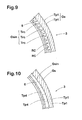
- Fig.9 shows a modification of the above-mentioned double layered structure, wherein the sidewall rubber Gs may be the same as above, but the inner sidewall rubber Gsin is formed by winding a cord-reinforced rubber tape Trc shown in Fig.1c.
- the cord-reinforced rubber tape Trc may be wound in an upper sidewall portion near the tire shoulder.
- the above-mentioned fiber containing rubber tape Trf or the under-mentioned pure rubber tape Tp4 may be wound.
- the steering stability may be further improved.
- organic cords for example, 840d nylon cords are preferably used.
- Fig.10 further shows a modification of the double-layered structure shown in Fig.9, wherein the sidewall rubber Gs is the same as above, but the inner sidewall rubber Gsin is formed by winding a pure rubber tape Tp4 which is made of a rubber compound harder than that of the sidewall rubber Gs for the purpose of increasing the rigidity of the sidewall portion 3. Furthermore, instead of winding the narrow pure rubber tape Tp4, the inner sidewall rubber Gsin may be formed by applying a relatively wide rubber strip which may be formed by means of an extruder.
- the JIS type-A-durometer hardness, 230 % modulus and Mooney viscosity are set to be higher than the sidewall rubber Gs and near the respective upper limits, namely, 95 degrees, 6.0 MPa and 73 ⁇ ML(1+4) ⁇ .
Landscapes
- Engineering & Computer Science (AREA)
- Mechanical Engineering (AREA)
- Tires In General (AREA)
- Tyre Moulding (AREA)
Applications Claiming Priority (4)
| Application Number | Priority Date | Filing Date | Title |
|---|---|---|---|
| JP2000330854A JP4160245B2 (ja) | 2000-10-30 | 2000-10-30 | 空気入りタイヤ及びその製造方法 |
| JP2000330854 | 2000-10-30 | ||
| JP2000361453A JP3774116B2 (ja) | 2000-11-28 | 2000-11-28 | 空気入りタイヤ |
| JP2000361453 | 2000-11-28 |
Publications (4)
| Publication Number | Publication Date |
|---|---|
| EP1201414A2 true EP1201414A2 (fr) | 2002-05-02 |
| EP1201414A3 EP1201414A3 (fr) | 2002-09-11 |
| EP1201414B1 EP1201414B1 (fr) | 2009-05-06 |
| EP1201414B2 EP1201414B2 (fr) | 2019-12-04 |
Family
ID=26603054
Family Applications (1)
| Application Number | Title | Priority Date | Filing Date |
|---|---|---|---|
| EP01125788.8A Expired - Lifetime EP1201414B2 (fr) | 2000-10-30 | 2001-10-29 | Procédé de fabrication d'un flanc de pneumatique |
Country Status (5)
| Country | Link |
|---|---|
| US (2) | US7060146B2 (fr) |
| EP (1) | EP1201414B2 (fr) |
| KR (1) | KR100850694B1 (fr) |
| CN (1) | CN100337810C (fr) |
| DE (1) | DE60138599D1 (fr) |
Cited By (19)
| Publication number | Priority date | Publication date | Assignee | Title |
|---|---|---|---|---|
| WO2004048129A1 (fr) * | 2002-11-25 | 2004-06-10 | Bridgestone Corporation | Pneumatique |
| WO2005105419A1 (fr) * | 2004-04-30 | 2005-11-10 | Pirelli Tyre S.P.A. | Procede de fabrication d'un pneu a flancs renforces pour roue de vehicule |
| EP1634727A1 (fr) * | 2004-09-13 | 2006-03-15 | Sumitomo Rubber Industries, Ltd. | Pneumatique et son procédé de fabrication |
| EP1555114A4 (fr) * | 2002-10-23 | 2006-05-03 | Bridgestone Corp | Procede de fabrication de pneus, dispositif d'estampage de caoutchouc de couverture utilise dans ce procede de fabrication, procede d'estampage d'element de feuille de caoutchouc, et dispositif d'estampage d'element de feuille de caoutchouc |
| EP1666236A1 (fr) * | 2004-12-02 | 2006-06-07 | Sumitomo Rubber Industries, Ltd. | Pneumatique |
| EP1685949A1 (fr) * | 2005-01-27 | 2006-08-02 | Continental Aktiengesellschaft | Procédé de fabrication de pneumatiques à partir d'éléments constructifs de pneumatique |
| EP1803545A3 (fr) * | 2005-12-28 | 2007-12-26 | Sumitomo Rubber Industries, Ltd. | Procédé de fabrication d'éléments en caoutchouc pour pneumatiques |
| RU2337823C2 (ru) * | 2004-04-30 | 2008-11-10 | Пирелли Тайр С.П.А. | Способ и устройство для изготовления шины, способной обеспечивать движение в спущенном состоянии, для колес транспортных средств |
| EP1995048A1 (fr) * | 2007-05-22 | 2008-11-26 | Continental Aktiengesellschaft | Procédé de fabrication d'un pneu de véhicule et pneu de véhicule |
| EP2191985A4 (fr) * | 2005-10-17 | 2010-10-06 | Bridgestone Corp | Pneumatique, appareil et procede de moulage d'un pneumatique |
| US7931767B2 (en) | 2003-06-30 | 2011-04-26 | Pirelli Pneumatici S.P.A. | Process for manufacturing elastomeric components of a tyre for vehicle wheels |
| EP1785284A3 (fr) * | 2005-11-09 | 2012-04-18 | Sumitomo Rubber Industries, Ltd. | Pneumatique avec épaulette et sa methode de fabrication |
| EP2805837A1 (fr) * | 2013-05-22 | 2014-11-26 | Nokian Renkaat Oyj | Pneu de véhicule |
| CN105437585A (zh) * | 2014-09-28 | 2016-03-30 | 青岛软控机电工程有限公司 | 一种轮胎缠绕机控制方法 |
| US9547629B2 (en) | 2013-11-29 | 2017-01-17 | Documill Oy | Efficient creation of web fonts |
| EP3538341A4 (fr) * | 2016-11-10 | 2020-06-10 | Bridgestone Americas Tire Operations, LLC | Pneu à bande de roulement de taille de ruban variable ainsi que système et procédé de fabrication de celui-ci |
| EP3725545A4 (fr) * | 2017-12-14 | 2021-08-25 | Bridgestone Corporation | Pneu |
| EP4183564A2 (fr) | 2021-11-18 | 2023-05-24 | Continental Reifen Deutschland GmbH | Procédé et dispositif de fabrication d'un pneu de véhicule et pneu de véhicule |
| EP4183563A2 (fr) | 2021-11-18 | 2023-05-24 | Continental Reifen Deutschland GmbH | Procédé et dispositif de fabrication d'un pneu de véhicule comprenant au moins une paroi latérale comprenant au moins deux sections et pneu de véhicule |
Families Citing this family (57)
| Publication number | Priority date | Publication date | Assignee | Title |
|---|---|---|---|---|
| US20020088529A1 (en) * | 2000-11-22 | 2002-07-11 | Bridgestone Corporation | Method for manufacturing pneumatic tire |
| US20050034802A1 (en) * | 2001-11-12 | 2005-02-17 | Jingo Shirasaka | Production method for unvulcanized rubber member and tire |
| JP4607420B2 (ja) * | 2002-11-25 | 2011-01-05 | 株式会社ブリヂストン | タイヤの製造方法 |
| JP3726085B2 (ja) * | 2003-03-14 | 2005-12-14 | 横浜ゴム株式会社 | 建設車両用ラジアルタイヤの製造方法 |
| EP1615782A1 (fr) * | 2003-03-26 | 2006-01-18 | Pirelli Pneumatici Societa' Per Azioni | Pneumatique pour vehicules a deux roues |
| JP2005225278A (ja) * | 2004-02-10 | 2005-08-25 | Sumitomo Rubber Ind Ltd | 空気入りタイヤ |
| JP4088260B2 (ja) * | 2004-03-03 | 2008-05-21 | 住友ゴム工業株式会社 | クリンチ用ゴム組成物およびそれを用いた空気入りタイヤ |
| JP4537806B2 (ja) * | 2004-08-31 | 2010-09-08 | 住友ゴム工業株式会社 | 空気入りタイヤ、及びその製造方法 |
| JP2006069130A (ja) * | 2004-09-03 | 2006-03-16 | Toyo Tire & Rubber Co Ltd | タイヤ及びタイヤ成型方法 |
| JP2006076200A (ja) * | 2004-09-10 | 2006-03-23 | Bridgestone Corp | ビードフィラの成形方法 |
| US7891394B2 (en) * | 2004-09-23 | 2011-02-22 | The Goodyear Tire & Rubber Company | Tire with puncture resistant sidewall |
| DE112004003006T5 (de) * | 2004-11-02 | 2007-10-11 | Toyo Tire & Rubber Co., Ltd. | Reifenherstellverfahren und Reifenherstellanlage |
| WO2006049222A1 (fr) * | 2004-11-04 | 2006-05-11 | Bridgestone Corporation | Procede de production de pneu |
| JP4581752B2 (ja) * | 2005-03-07 | 2010-11-17 | 横浜ゴム株式会社 | 空気入りタイヤの製造方法及び空気入りタイヤ |
| JP4914024B2 (ja) | 2005-04-22 | 2012-04-11 | 東洋ゴム工業株式会社 | 空気入りタイヤ及び空気入りタイヤの製造方法 |
| FR2887814A1 (fr) * | 2005-06-30 | 2007-01-05 | Michelin Soc Tech | Pneumatique pour vehicules lourds |
| WO2007024804A1 (fr) * | 2005-08-22 | 2007-03-01 | Bridgestone/Firestone North American Tire, Llc | Pneumatiques |
| JP4912645B2 (ja) * | 2005-09-06 | 2012-04-11 | 東洋ゴム工業株式会社 | 空気入りタイヤ |
| JP5054303B2 (ja) | 2005-12-20 | 2012-10-24 | 住友ゴム工業株式会社 | 空気入りタイヤ及びその製造方法 |
| JP4464917B2 (ja) * | 2005-12-28 | 2010-05-19 | 住友ゴム工業株式会社 | 空気入りタイヤ |
| KR100794736B1 (ko) * | 2006-06-29 | 2008-01-15 | 금호타이어 주식회사 | 공기입 타이어 |
| CN101505949B (zh) * | 2006-08-09 | 2013-11-06 | 倍耐力轮胎股份公司 | 用于构建充气轮胎的方法和设备 |
| JP5174338B2 (ja) * | 2006-09-29 | 2013-04-03 | 株式会社ブリヂストン | 航空機用ラジアルタイヤおよびその製造方法 |
| EP2058142B1 (fr) * | 2006-10-30 | 2012-07-25 | The Yokohama Rubber Co., Ltd. | Pneumatique et son procede de fabrication |
| US20080115871A1 (en) * | 2006-11-16 | 2008-05-22 | Paul Harry Sandstrom | Tire having a sidewall component containing a dispersion of adhesive coated short carbon fiber reinforcement |
| CN101595004A (zh) * | 2007-02-15 | 2009-12-02 | 巴特尔机械系统有限责任公司 | 具有锥形胎圈的轮胎和制造轮胎的方法 |
| JP4780796B2 (ja) * | 2007-08-09 | 2011-09-28 | 東洋ゴム工業株式会社 | 空気入りタイヤの製造方法 |
| EP2209610B1 (fr) * | 2007-10-31 | 2014-06-04 | Pirelli Tyre S.p.A. | Procédé de fabrication de pneumatiques et pneumatique obtenu selon ledit procédé |
| JP4220569B1 (ja) * | 2007-11-05 | 2009-02-04 | 住友ゴム工業株式会社 | 空気入りタイヤ |
| US8459322B2 (en) * | 2007-12-18 | 2013-06-11 | The Goodyear Tire & Rubber Company | Pneumatic tire |
| JP4286319B1 (ja) * | 2008-02-01 | 2009-06-24 | 住友ゴム工業株式会社 | 空気入りタイヤ |
| CN102046362B (zh) * | 2008-04-18 | 2015-04-01 | 倍耐力轮胎股份公司 | 用于构建轮胎的方法和设备 |
| JP5358681B2 (ja) | 2008-05-28 | 2013-12-04 | ピレリ・タイヤ・ソチエタ・ペル・アツィオーニ | タイヤを構築する方法および装置 |
| WO2009157028A1 (fr) | 2008-06-27 | 2009-12-30 | Pirelli Tyre S.P.A. | Processus et installation de construction de pneumatiques pour roues de véhicule |
| BRPI0823352B1 (pt) | 2008-12-02 | 2019-01-29 | Pirelli | processo para fabricar pneus para rodas de veículos |
| WO2010126091A1 (fr) * | 2009-04-28 | 2010-11-04 | 株式会社ブリヂストン | Pneu |
| US8453693B2 (en) * | 2009-11-18 | 2013-06-04 | The Goodyear Tire & Rubber Company | Pneumatic tire |
| US8413700B2 (en) * | 2010-02-04 | 2013-04-09 | Bridgestone Americas Tire Operations, Llc | Tire having staggered turn-ups |
| US8517072B2 (en) * | 2010-02-04 | 2013-08-27 | Bridgestone Americas Tire Operations, Llc | Tire having gum strip and chafer |
| JP4941580B2 (ja) * | 2010-06-23 | 2012-05-30 | 横浜ゴム株式会社 | 空気入りタイヤ |
| JP5379313B2 (ja) * | 2010-10-29 | 2013-12-25 | 株式会社ブリヂストン | 台タイヤの製造方法及びタイヤの製造方法 |
| US8454778B2 (en) | 2010-11-15 | 2013-06-04 | Ramendra Nath Majumdar | Pneumatic tire with barrier layer and method of making the same |
| JP5363600B2 (ja) * | 2012-02-21 | 2013-12-11 | 住友ゴム工業株式会社 | 空気入りタイヤ |
| TWI572500B (zh) * | 2012-05-23 | 2017-03-01 | Kenda Rubber Ind Co Ltd | Bike tires |
| US9381781B2 (en) | 2012-07-30 | 2016-07-05 | The Goodyear Tire & Rubber Company | Bonding to a pneumatic tire |
| CA2902328A1 (fr) | 2013-03-13 | 2014-10-09 | Basf Se | Calandrage interieur pour ensemble pneu |
| US9505276B2 (en) | 2014-12-05 | 2016-11-29 | The Goodyear Tire & Rubber Company | Filter for a pneumatic tire |
| JP6015798B2 (ja) * | 2015-03-26 | 2016-10-26 | 横浜ゴム株式会社 | 空気入りタイヤ |
| JP6687381B2 (ja) * | 2015-12-18 | 2020-04-22 | Toyo Tire株式会社 | 空気入りタイヤの製造方法 |
| JP6304285B2 (ja) * | 2016-02-23 | 2018-04-04 | 横浜ゴム株式会社 | 空気入りタイヤ |
| US20200122508A1 (en) * | 2017-06-30 | 2020-04-23 | Kolon Industries, Inc. | Rubber reinforcing material with reduced weight, method for preparing the same and tire comprising the same |
| WO2019035281A1 (fr) * | 2017-08-18 | 2019-02-21 | 横浜ゴム株式会社 | Pneumatique |
| JP6582104B1 (ja) * | 2018-10-03 | 2019-09-25 | Toyo Tire株式会社 | タイヤの製造方法 |
| JP6698146B1 (ja) * | 2018-12-26 | 2020-05-27 | Toyo Tire株式会社 | タイヤおよびタイヤの製造方法 |
| JP7614849B2 (ja) * | 2021-01-08 | 2025-01-16 | Toyo Tire株式会社 | タイヤ製造装置及びタイヤ製造方法 |
| EP4363206A4 (fr) | 2021-06-01 | 2025-05-07 | Satpathy, Smitiparna | Procédé de fabrication d'un pneu à enveloppe intégrée |
| ES2942787B2 (es) * | 2021-12-03 | 2023-12-28 | Advantaria S L | Neumatico menos contaminante y con mayor vida util |
Family Cites Families (37)
| Publication number | Priority date | Publication date | Assignee | Title |
|---|---|---|---|---|
| GB537780A (en) * | 1939-03-28 | 1941-07-07 | Alfred Buechi | Improvements in or relating to charging devices for internal combustion engines |
| GB802898A (en) * | 1956-05-16 | 1958-10-15 | Firestone Tire & Rubber Co | Improvements in method of forming an endless tire tread and sidewall portion on a carcass band and product thereof |
| DE1729842C3 (de) * | 1962-05-01 | 1974-01-31 | Amf Inc., New York, N.Y. (V.St.A.) | Vorrichtung zum Aufbringen der Rohlauffläche auf eine Reifenkarkasse |
| US3251722A (en) * | 1962-05-01 | 1966-05-17 | Voit Rubber Corp | Method of automatically applying a variable thickness elastomeric layer on pneumatic tire casings |
| NL156352B (nl) † | 1965-12-18 | 1978-04-17 | Pirelli | Gevulcaniseerde luchtband voor een voertuigwiel. |
| BE789075A (fr) † | 1971-09-29 | 1973-01-15 | Pirelli | Bandage pneumatique pour roue de vehicule a resistance elevee aux forces tangentielles qu'il subit au passage de trajectoires courbes |
| US3904463A (en) * | 1972-02-03 | 1975-09-09 | Michelin & Cie | Radial tire with additional sidewall reinforcement |
| FR2261888B1 (fr) * | 1974-02-26 | 1976-12-10 | Kleber Colombes | |
| ZA869680B (en) * | 1985-12-30 | 1987-09-30 | Monsanto Co | Rubber blends |
| LU86897A1 (fr) * | 1986-06-02 | 1987-11-11 | Goodyear Tire & Rubber | Procede et appareil pour la fabrication d'un bandage pneumatique a plusieurs elements |
| JPH0618950B2 (ja) * | 1986-06-17 | 1994-03-16 | 株式会社ブリヂストン | ゴム組成物 |
| GB8726628D0 (en) † | 1987-11-13 | 1987-12-16 | Holroyd Associates Ltd | Bead filler construction |
| US20020134480A1 (en) * | 1989-03-02 | 2002-09-26 | Sumitomo Rubber Industries, Ltd. | Pneumatic tire |
| JPH045110A (ja) * | 1990-04-20 | 1992-01-09 | Sumitomo Rubber Ind Ltd | 自動二輪車用ラジアルタイヤ |
| DE4020531A1 (de) * | 1990-06-28 | 1992-01-02 | Continental Ag | Fahrzeugluftreifen |
| US5532312A (en) * | 1990-08-15 | 1996-07-02 | Exxon Chemical Patents, Inc. | Tire sidewall composition |
| NL9002848A (nl) † | 1990-12-21 | 1992-07-16 | A R T | Inrichting voor het maken van een samenstel dat bestaat uit een van een vulstrook voorziene bandhiel. |
| DE4134323A1 (de) * | 1991-10-17 | 1993-04-22 | Continental Ag | Verfahren zur herstellung einer wickelbandage fuer einen fahrzeugluftreifen |
| US5244028A (en) * | 1992-05-20 | 1993-09-14 | The Goodyear Tire & Rubber Company | Tire sidewall composition containing silica having low pH |
| CA2111349C (fr) * | 1992-12-14 | 2003-05-06 | Yuichi Saito | Pneus radiaux |
| JPH08238910A (ja) * | 1995-03-03 | 1996-09-17 | Bridgestone Corp | 空気入りタイヤ |
| JP3786471B2 (ja) * | 1996-07-03 | 2006-06-14 | 横浜ゴム株式会社 | 空気入りタイヤおよびその製造方法 |
| JP3165645B2 (ja) † | 1996-10-04 | 2001-05-14 | 住友ゴム工業株式会社 | 空気入りラジアルタイヤ |
| US6039826A (en) * | 1997-04-22 | 2000-03-21 | The Yokohama Rubber Co., Ltd. | Method of forming green tire with strip winding |
| WO1998054011A1 (fr) * | 1997-05-26 | 1998-12-03 | Bridgestone Corporation | Pneumatique de securite |
| JP3232262B2 (ja) * | 1997-05-30 | 2001-11-26 | 住友ゴム工業株式会社 | 重荷重用空気入りタイヤ |
| JP3782875B2 (ja) * | 1997-09-30 | 2006-06-07 | 横浜ゴム株式会社 | 空気入りラジアルタイヤ |
| EP0943421B1 (fr) † | 1997-11-28 | 2003-05-28 | Pirelli Pneumatici Societa' Per Azioni | Procédé pour la fabrication de bandages pneumatiques pour roues de véhicule |
| DE69719771T2 (de) † | 1997-12-30 | 2003-12-11 | Pirelli Pneumatici S.P.A., Milano | Verfahren zur Herstellung von Luftreifen für Fahrzeugräder |
| DE19831747A1 (de) † | 1998-07-15 | 2000-01-20 | Continental Ag | Verfahren zur Herstellung eines Luftreifens |
| US6046266A (en) * | 1998-09-24 | 2000-04-04 | The Goodyear Tire & Rubber Company | Tire with silica reinforced tread and/or sidewall components |
| JP3352045B2 (ja) * | 1999-03-04 | 2002-12-03 | 住友ゴム工業株式会社 | タイヤゴム部材形成用のゴムストリップ、それを用いたタイヤ、及びゴムストリップの製造装置 |
| JP2001080318A (ja) * | 1999-09-10 | 2001-03-27 | Bridgestone Corp | 空気入りタイヤ |
| US6740280B1 (en) † | 2000-04-10 | 2004-05-25 | The Goodyear Tire & Rubber Company | Tire construction method for improving tire uniformity |
| JP3774107B2 (ja) * | 2000-06-07 | 2006-05-10 | 住友ゴム工業株式会社 | 空気入りタイヤ |
| US20020088529A1 (en) † | 2000-11-22 | 2002-07-11 | Bridgestone Corporation | Method for manufacturing pneumatic tire |
| US6939920B2 (en) * | 2001-01-08 | 2005-09-06 | The Goodyear Tire & Rubber Company | Tire sidewall compounds having improved flex fatigue and tread compound having improved tear strength |
-
2001
- 2001-10-29 KR KR1020010066707A patent/KR100850694B1/ko not_active Expired - Fee Related
- 2001-10-29 EP EP01125788.8A patent/EP1201414B2/fr not_active Expired - Lifetime
- 2001-10-29 DE DE60138599T patent/DE60138599D1/de not_active Expired - Lifetime
- 2001-10-30 CN CNB011375876A patent/CN100337810C/zh not_active Expired - Lifetime
- 2001-10-30 US US09/984,379 patent/US7060146B2/en not_active Expired - Lifetime
-
2005
- 2005-02-23 US US11/062,443 patent/US7513281B2/en not_active Expired - Lifetime
Cited By (27)
| Publication number | Priority date | Publication date | Assignee | Title |
|---|---|---|---|---|
| EP1555114A4 (fr) * | 2002-10-23 | 2006-05-03 | Bridgestone Corp | Procede de fabrication de pneus, dispositif d'estampage de caoutchouc de couverture utilise dans ce procede de fabrication, procede d'estampage d'element de feuille de caoutchouc, et dispositif d'estampage d'element de feuille de caoutchouc |
| US7622013B2 (en) | 2002-10-23 | 2009-11-24 | Bridgestone Corporation | Tire manufacturing method, cover rubber stamping device used therefore, tire, as well as rubber sheet member stamping method, and device |
| WO2004048129A1 (fr) * | 2002-11-25 | 2004-06-10 | Bridgestone Corporation | Pneumatique |
| EP1584493A4 (fr) * | 2002-11-25 | 2006-06-14 | Bridgestone Corp | Pneumatique |
| US7931767B2 (en) | 2003-06-30 | 2011-04-26 | Pirelli Pneumatici S.P.A. | Process for manufacturing elastomeric components of a tyre for vehicle wheels |
| WO2005105419A1 (fr) * | 2004-04-30 | 2005-11-10 | Pirelli Tyre S.P.A. | Procede de fabrication d'un pneu a flancs renforces pour roue de vehicule |
| RU2337823C2 (ru) * | 2004-04-30 | 2008-11-10 | Пирелли Тайр С.П.А. | Способ и устройство для изготовления шины, способной обеспечивать движение в спущенном состоянии, для колес транспортных средств |
| EP1634727A1 (fr) * | 2004-09-13 | 2006-03-15 | Sumitomo Rubber Industries, Ltd. | Pneumatique et son procédé de fabrication |
| US7628190B2 (en) | 2004-09-13 | 2009-12-08 | Sumitomo Rubber Industries, Ltd. | Pneumatic tire and manufacturing method of the same |
| EP1666236A1 (fr) * | 2004-12-02 | 2006-06-07 | Sumitomo Rubber Industries, Ltd. | Pneumatique |
| CN1781739B (zh) * | 2004-12-02 | 2011-08-03 | 住友橡胶工业株式会社 | 充气轮胎 |
| EP1685949A1 (fr) * | 2005-01-27 | 2006-08-02 | Continental Aktiengesellschaft | Procédé de fabrication de pneumatiques à partir d'éléments constructifs de pneumatique |
| EP2191985A4 (fr) * | 2005-10-17 | 2010-10-06 | Bridgestone Corp | Pneumatique, appareil et procede de moulage d'un pneumatique |
| EP1785284A3 (fr) * | 2005-11-09 | 2012-04-18 | Sumitomo Rubber Industries, Ltd. | Pneumatique avec épaulette et sa methode de fabrication |
| EP1803545A3 (fr) * | 2005-12-28 | 2007-12-26 | Sumitomo Rubber Industries, Ltd. | Procédé de fabrication d'éléments en caoutchouc pour pneumatiques |
| EP1995048A1 (fr) * | 2007-05-22 | 2008-11-26 | Continental Aktiengesellschaft | Procédé de fabrication d'un pneu de véhicule et pneu de véhicule |
| EP2805837A1 (fr) * | 2013-05-22 | 2014-11-26 | Nokian Renkaat Oyj | Pneu de véhicule |
| CN104175813A (zh) * | 2013-05-22 | 2014-12-03 | 诺基安伦卡特股份有限公司 | 车辆轮胎 |
| US9547629B2 (en) | 2013-11-29 | 2017-01-17 | Documill Oy | Efficient creation of web fonts |
| CN105437585A (zh) * | 2014-09-28 | 2016-03-30 | 青岛软控机电工程有限公司 | 一种轮胎缠绕机控制方法 |
| CN105437585B (zh) * | 2014-09-28 | 2018-01-19 | 青岛软控机电工程有限公司 | 一种轮胎缠绕机控制方法 |
| EP3538341A4 (fr) * | 2016-11-10 | 2020-06-10 | Bridgestone Americas Tire Operations, LLC | Pneu à bande de roulement de taille de ruban variable ainsi que système et procédé de fabrication de celui-ci |
| US11446853B2 (en) | 2016-11-10 | 2022-09-20 | Bridgestone Americas Tire Operations, Llc | Tire with variable ribbon size tread and system and method for making same |
| EP3725545A4 (fr) * | 2017-12-14 | 2021-08-25 | Bridgestone Corporation | Pneu |
| EP4183564A2 (fr) | 2021-11-18 | 2023-05-24 | Continental Reifen Deutschland GmbH | Procédé et dispositif de fabrication d'un pneu de véhicule et pneu de véhicule |
| EP4183563A2 (fr) | 2021-11-18 | 2023-05-24 | Continental Reifen Deutschland GmbH | Procédé et dispositif de fabrication d'un pneu de véhicule comprenant au moins une paroi latérale comprenant au moins deux sections et pneu de véhicule |
| EP4183563B1 (fr) | 2021-11-18 | 2025-06-04 | Continental Reifen Deutschland GmbH | Procédé et dispositif de fabrication d'un pneu de véhicule comprenant au moins une paroi latérale comprenant au moins deux sections et pneu de véhicule |
Also Published As
| Publication number | Publication date |
|---|---|
| EP1201414B1 (fr) | 2009-05-06 |
| DE60138599D1 (de) | 2009-06-18 |
| US20020074077A1 (en) | 2002-06-20 |
| US20050145314A1 (en) | 2005-07-07 |
| KR20020033540A (ko) | 2002-05-07 |
| EP1201414A3 (fr) | 2002-09-11 |
| CN100337810C (zh) | 2007-09-19 |
| KR100850694B1 (ko) | 2008-08-06 |
| US7513281B2 (en) | 2009-04-07 |
| EP1201414B2 (fr) | 2019-12-04 |
| CN1350919A (zh) | 2002-05-29 |
| US7060146B2 (en) | 2006-06-13 |
Similar Documents
| Publication | Publication Date | Title |
|---|---|---|
| EP1201414B1 (fr) | Procédé de fabrication d'un flanc de pneumatique | |
| US6273162B1 (en) | Pneumatic tire with specified bead portion | |
| US6135182A (en) | Heavy duty pneumatic radial tires with anisotropic bead reinforcing rubber | |
| US7409974B2 (en) | Self-supporting pneumatic tire with a partial inner liner | |
| JP4546812B2 (ja) | 空気入りタイヤ | |
| JP3774116B2 (ja) | 空気入りタイヤ | |
| EP1162087B1 (fr) | Bandage pneumatique pour véhicule | |
| EP0605177B1 (fr) | Bandage pneumatique | |
| EP2308694B1 (fr) | Pneu | |
| EP1974958B1 (fr) | Pneumatique | |
| EP2463124A2 (fr) | Pneu | |
| US6736178B2 (en) | Pneumatic tire with specified bead portion | |
| EP1142695A2 (fr) | Procédé pour la confection de pneus | |
| EP2974891B1 (fr) | Pneumatique | |
| EP1275526B1 (fr) | Bandage pneumatique | |
| EP1454732A1 (fr) | Procede de production d'un element en caoutchouc non vulcanise et d'un bandage | |
| US4705091A (en) | Heavy duty pneumatic radial tires | |
| EP1795376A1 (fr) | Pneu à flancs renforcés et procédé de fabrication du pneu à flancs renforcés | |
| US20160288574A1 (en) | Crown reinforcement for a pneumatic tire | |
| EP1072444A1 (fr) | Pneu radial resistant | |
| US20160288573A1 (en) | Continuous crown reinforcement for a pneumatic tire | |
| US20050034802A1 (en) | Production method for unvulcanized rubber member and tire | |
| JP4944487B2 (ja) | ランフラットタイヤ及びその製造方法 | |
| EP4371751B1 (fr) | Procédé de production d'un pneumatique comprenant une couche d'étanchéité | |
| EP3176005A1 (fr) | Construction mono-courroie bidirectionnelle pour un pneumatique |
Legal Events
| Date | Code | Title | Description |
|---|---|---|---|
| PUAI | Public reference made under article 153(3) epc to a published international application that has entered the european phase |
Free format text: ORIGINAL CODE: 0009012 |
|
| AK | Designated contracting states |
Kind code of ref document: A2 Designated state(s): AT BE CH CY DE DK ES FI FR GB GR IE IT LI LU MC NL PT SE TR |
|
| AX | Request for extension of the european patent |
Free format text: AL;LT;LV;MK;RO;SI |
|
| PUAL | Search report despatched |
Free format text: ORIGINAL CODE: 0009013 |
|
| RIC1 | Information provided on ipc code assigned before grant |
Free format text: 7B 29D 30/72 A, 7B 29D 30/50 B |
|
| AK | Designated contracting states |
Kind code of ref document: A3 Designated state(s): AT BE CH CY DE DK ES FI FR GB GR IE IT LI LU MC NL PT SE TR |
|
| AX | Request for extension of the european patent |
Free format text: AL;LT;LV;MK;RO;SI |
|
| AKX | Designation fees paid | ||
| 17P | Request for examination filed |
Effective date: 20030219 |
|
| RBV | Designated contracting states (corrected) |
Designated state(s): DE FR GB |
|
| REG | Reference to a national code |
Ref country code: DE Ref legal event code: 8566 |
|
| 17Q | First examination report despatched |
Effective date: 20060727 |
|
| 17Q | First examination report despatched |
Effective date: 20060727 |
|
| GRAP | Despatch of communication of intention to grant a patent |
Free format text: ORIGINAL CODE: EPIDOSNIGR1 |
|
| GRAS | Grant fee paid |
Free format text: ORIGINAL CODE: EPIDOSNIGR3 |
|
| GRAA | (expected) grant |
Free format text: ORIGINAL CODE: 0009210 |
|
| AK | Designated contracting states |
Kind code of ref document: B1 Designated state(s): DE FR GB |
|
| REG | Reference to a national code |
Ref country code: GB Ref legal event code: FG4D |
|
| REF | Corresponds to: |
Ref document number: 60138599 Country of ref document: DE Date of ref document: 20090618 Kind code of ref document: P |
|
| PLBI | Opposition filed |
Free format text: ORIGINAL CODE: 0009260 |
|
| PLAX | Notice of opposition and request to file observation + time limit sent |
Free format text: ORIGINAL CODE: EPIDOSNOBS2 |
|
| 26 | Opposition filed |
Opponent name: PIRELLI TYRE S.P.A. Effective date: 20100208 |
|
| PLAF | Information modified related to communication of a notice of opposition and request to file observations + time limit |
Free format text: ORIGINAL CODE: EPIDOSCOBS2 |
|
| PLBB | Reply of patent proprietor to notice(s) of opposition received |
Free format text: ORIGINAL CODE: EPIDOSNOBS3 |
|
| PLAB | Opposition data, opponent's data or that of the opponent's representative modified |
Free format text: ORIGINAL CODE: 0009299OPPO |
|
| R26 | Opposition filed (corrected) |
Opponent name: PIRELLI TYRE S.P.A. Effective date: 20100208 |
|
| RDAF | Communication despatched that patent is revoked |
Free format text: ORIGINAL CODE: EPIDOSNREV1 |
|
| APBM | Appeal reference recorded |
Free format text: ORIGINAL CODE: EPIDOSNREFNO |
|
| APBP | Date of receipt of notice of appeal recorded |
Free format text: ORIGINAL CODE: EPIDOSNNOA2O |
|
| APAH | Appeal reference modified |
Free format text: ORIGINAL CODE: EPIDOSCREFNO |
|
| APBQ | Date of receipt of statement of grounds of appeal recorded |
Free format text: ORIGINAL CODE: EPIDOSNNOA3O |
|
| REG | Reference to a national code |
Ref country code: FR Ref legal event code: PLFP Year of fee payment: 16 |
|
| APBU | Appeal procedure closed |
Free format text: ORIGINAL CODE: EPIDOSNNOA9O |
|
| REG | Reference to a national code |
Ref country code: FR Ref legal event code: PLFP Year of fee payment: 17 |
|
| PLAP | Information related to despatch of examination report in opposition + time limit deleted |
Free format text: ORIGINAL CODE: EPIDOSDORE2 |
|
| PLAY | Examination report in opposition despatched + time limit |
Free format text: ORIGINAL CODE: EPIDOSNORE2 |
|
| PLBC | Reply to examination report in opposition received |
Free format text: ORIGINAL CODE: EPIDOSNORE3 |
|
| PLAY | Examination report in opposition despatched + time limit |
Free format text: ORIGINAL CODE: EPIDOSNORE2 |
|
| PLBC | Reply to examination report in opposition received |
Free format text: ORIGINAL CODE: EPIDOSNORE3 |
|
| PLAY | Examination report in opposition despatched + time limit |
Free format text: ORIGINAL CODE: EPIDOSNORE2 |
|
| REG | Reference to a national code |
Ref country code: FR Ref legal event code: PLFP Year of fee payment: 18 |
|
| PGFP | Annual fee paid to national office [announced via postgrant information from national office to epo] |
Ref country code: FR Payment date: 20180913 Year of fee payment: 18 |
|
| PLBC | Reply to examination report in opposition received |
Free format text: ORIGINAL CODE: EPIDOSNORE3 |
|
| PLAY | Examination report in opposition despatched + time limit |
Free format text: ORIGINAL CODE: EPIDOSNORE2 |
|
| PLBC | Reply to examination report in opposition received |
Free format text: ORIGINAL CODE: EPIDOSNORE3 |
|
| PGFP | Annual fee paid to national office [announced via postgrant information from national office to epo] |
Ref country code: GB Payment date: 20181024 Year of fee payment: 18 |
|
| RIC2 | Information provided on ipc code assigned after grant |
Ipc: B29D 30/50 20060101ALI20190401BHEP Ipc: B29D 30/72 20060101AFI20190401BHEP Ipc: B29C 48/07 20190101ALI20190401BHEP Ipc: B60C 13/04 20060101ALI20190401BHEP |
|
| PUAH | Patent maintained in amended form |
Free format text: ORIGINAL CODE: 0009272 |
|
| STAA | Information on the status of an ep patent application or granted ep patent |
Free format text: STATUS: PATENT MAINTAINED AS AMENDED |
|
| 27A | Patent maintained in amended form |
Effective date: 20191204 |
|
| AK | Designated contracting states |
Kind code of ref document: B2 Designated state(s): DE FR GB |
|
| REG | Reference to a national code |
Ref country code: DE Ref legal event code: R102 Ref document number: 60138599 Country of ref document: DE |
|
| GBPC | Gb: european patent ceased through non-payment of renewal fee |
Effective date: 20191029 |
|
| PG25 | Lapsed in a contracting state [announced via postgrant information from national office to epo] |
Ref country code: FR Free format text: LAPSE BECAUSE OF NON-PAYMENT OF DUE FEES Effective date: 20191031 Ref country code: GB Free format text: LAPSE BECAUSE OF NON-PAYMENT OF DUE FEES Effective date: 20191029 |
|
| PGFP | Annual fee paid to national office [announced via postgrant information from national office to epo] |
Ref country code: DE Payment date: 20201013 Year of fee payment: 20 |
|
| REG | Reference to a national code |
Ref country code: DE Ref legal event code: R071 Ref document number: 60138599 Country of ref document: DE |