EP1201488B1 - Elektrisches Fahrzeug und zugehöriges Transportverfahren - Google Patents
Elektrisches Fahrzeug und zugehöriges Transportverfahren Download PDFInfo
- Publication number
- EP1201488B1 EP1201488B1 EP01125918A EP01125918A EP1201488B1 EP 1201488 B1 EP1201488 B1 EP 1201488B1 EP 01125918 A EP01125918 A EP 01125918A EP 01125918 A EP01125918 A EP 01125918A EP 1201488 B1 EP1201488 B1 EP 1201488B1
- Authority
- EP
- European Patent Office
- Prior art keywords
- brake
- percentage
- speed
- control
- accelerator
- Prior art date
- Legal status (The legal status is an assumption and is not a legal conclusion. Google has not performed a legal analysis and makes no representation as to the accuracy of the status listed.)
- Expired - Lifetime
Links
Images











Classifications
-
- B—PERFORMING OPERATIONS; TRANSPORTING
- B62—LAND VEHICLES FOR TRAVELLING OTHERWISE THAN ON RAILS
- B62D—MOTOR VEHICLES; TRAILERS
- B62D11/00—Steering non-deflectable wheels; Steering endless tracks or the like
- B62D11/001—Steering non-deflectable wheels; Steering endless tracks or the like control systems
- B62D11/003—Electric or electronic control systems
-
- B—PERFORMING OPERATIONS; TRANSPORTING
- B60—VEHICLES IN GENERAL
- B60L—PROPULSION OF ELECTRICALLY-PROPELLED VEHICLES; SUPPLYING ELECTRIC POWER FOR AUXILIARY EQUIPMENT OF ELECTRICALLY-PROPELLED VEHICLES; ELECTRODYNAMIC BRAKE SYSTEMS FOR VEHICLES IN GENERAL; MAGNETIC SUSPENSION OR LEVITATION FOR VEHICLES; MONITORING OPERATING VARIABLES OF ELECTRICALLY-PROPELLED VEHICLES; ELECTRIC SAFETY DEVICES FOR ELECTRICALLY-PROPELLED VEHICLES
- B60L15/00—Methods, circuits, or devices for controlling the traction-motor speed of electrically-propelled vehicles
- B60L15/20—Methods, circuits, or devices for controlling the traction-motor speed of electrically-propelled vehicles for control of the vehicle or its driving motor to achieve a desired performance, e.g. speed, torque, programmed variation of speed
- B60L15/2036—Electric differentials, e.g. for supporting steering vehicles
-
- B—PERFORMING OPERATIONS; TRANSPORTING
- B62—LAND VEHICLES FOR TRAVELLING OTHERWISE THAN ON RAILS
- B62D—MOTOR VEHICLES; TRAILERS
- B62D11/00—Steering non-deflectable wheels; Steering endless tracks or the like
- B62D11/02—Steering non-deflectable wheels; Steering endless tracks or the like by differentially driving ground-engaging elements on opposite vehicle sides
- B62D11/04—Steering non-deflectable wheels; Steering endless tracks or the like by differentially driving ground-engaging elements on opposite vehicle sides by means of separate power sources
-
- B—PERFORMING OPERATIONS; TRANSPORTING
- B62—LAND VEHICLES FOR TRAVELLING OTHERWISE THAN ON RAILS
- B62D—MOTOR VEHICLES; TRAILERS
- B62D51/00—Motor vehicles characterised by the driver not being seated
- B62D51/04—Motor vehicles characterised by the driver not being seated the driver walking
-
- B—PERFORMING OPERATIONS; TRANSPORTING
- B60—VEHICLES IN GENERAL
- B60Y—INDEXING SCHEME RELATING TO ASPECTS CROSS-CUTTING VEHICLE TECHNOLOGY
- B60Y2200/00—Type of vehicle
- B60Y2200/20—Off-Road Vehicles
- B60Y2200/22—Agricultural vehicles
- B60Y2200/225—Walk behind vehicles, e.g. motorized wheel barrows
-
- Y—GENERAL TAGGING OF NEW TECHNOLOGICAL DEVELOPMENTS; GENERAL TAGGING OF CROSS-SECTIONAL TECHNOLOGIES SPANNING OVER SEVERAL SECTIONS OF THE IPC; TECHNICAL SUBJECTS COVERED BY FORMER USPC CROSS-REFERENCE ART COLLECTIONS [XRACs] AND DIGESTS
- Y02—TECHNOLOGIES OR APPLICATIONS FOR MITIGATION OR ADAPTATION AGAINST CLIMATE CHANGE
- Y02T—CLIMATE CHANGE MITIGATION TECHNOLOGIES RELATED TO TRANSPORTATION
- Y02T10/00—Road transport of goods or passengers
- Y02T10/60—Other road transportation technologies with climate change mitigation effect
- Y02T10/64—Electric machine technologies in electromobility
-
- Y—GENERAL TAGGING OF NEW TECHNOLOGICAL DEVELOPMENTS; GENERAL TAGGING OF CROSS-SECTIONAL TECHNOLOGIES SPANNING OVER SEVERAL SECTIONS OF THE IPC; TECHNICAL SUBJECTS COVERED BY FORMER USPC CROSS-REFERENCE ART COLLECTIONS [XRACs] AND DIGESTS
- Y02—TECHNOLOGIES OR APPLICATIONS FOR MITIGATION OR ADAPTATION AGAINST CLIMATE CHANGE
- Y02T—CLIMATE CHANGE MITIGATION TECHNOLOGIES RELATED TO TRANSPORTATION
- Y02T10/00—Road transport of goods or passengers
- Y02T10/60—Other road transportation technologies with climate change mitigation effect
- Y02T10/72—Electric energy management in electromobility
Definitions
- This invention relates to an electric vehicle having left and right electric motors driving left and right driven wheel, and in particular to an associated transit control method according to the preamble part of claim 1.
- Ultramobile machine is a term which refers generally to dollies used for loading and unloading; cultivators and tractors used in farming; mowers for cutting grass; and snow-removers and so on.
- utility machines there are electric vehicles propelled by electric motors.
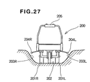
- An electric vehicle of this kind is referred to in Japanese Patent Laid-Open Publication No. SHO-50-107619 , "Steering Control Apparatus of Electric Dolly". This electric dolly is shown in Fig. 27 hereof.
- left and right electric motors (not shown) of an electric dolly 200 drive left and right driven wheels 201L, 201R to propel the electric dolly 200 along a path 202.
- the electric dolly 200 is traveling it deviates from the path 202 and a left side sensor 204L touches a left side slope 203L, the right side electric motor reverse-rotates to change the direction of the electric dolly 200 so that it returns to the path 202.
- the left side electric motor reverse-rotates to change the direction of the electric dolly 200 so that it returns to the path 202.
- the electric dolly 200 starts to change direction only after one of the left and right sensors 204L, 204R has made contact with the respective slope 203L or 203R, it deviates relatively far from the path 202 before changing direction. Consequently, the electric dolly 200 snakes as it travels.
- This snaking can be prevented by the driver changing the direction of the electric dolly 200 before either of the left and right sensors 204L, 204R touches the respective slope 203L or 203R.
- the driver to change the direction of the electric dolly 200 without relying on the left and right sensors 204L and 204R, it is necessary for the driver to grip an operating handle 205 strongly and turn the electric dolly 200 with great force.
- the electric dolly 200 becomes unsteady and difficult to keep in a good traveling attitude.
- the supplies of power to the left and right electric motors are altered in correspondence with the angle of inclination of the operating lever, essentially irrespective of the speed of the vehicle. And consequently, for example with an electric dolly, although there is no problem when the speed of the dolly is low, if the operating lever is operated when the speed is high, the dolly is liable to turn excessively due to inertial force.
- a transit control method is disclosed in US 4,527,648 A describing the control of a battery-powered electric vehicle having left and right electric motors for driving left and right driven wheels and left and right brakes for adjusting the speeds of the left and right driven wheels, respectively.
- a user is allowed to switch the speed of each electric motor between an off-state, a low speed and a high speed by operating respective switches which connect the motors directly to the batteries or via a resistor.
- the left and right brakes are mechanically operated caliper brakes which interact with the rim of the respective wheel and which are connected to the respective brake lever via a brake cable.
- US 6,098,385 disclosing a walk-behind lawn mower having a rearwardly extending handle bar mounting accelerator and brake levers.
- the known mower further comprises left and right driving wheels driven by an engine, wherein left and right control levers mounted to the handle bar can be operated to respectively control the rotation of said drive wheels by means of controlling the engagement of respective left and right clutch elements.
- the present invention provides a transit control method for an electric vehicle having left and right electric motors for driving left and right driven wheels and having left and right brakes for adjusting the speeds of the left and right driven wheels, the method including the steps of: substituting the positions of an accelerator lever and left and right speed control levers controlled by an operator as an accelerator angle, a left brake angle and a right brake angle; converting the accelerator angle, the left brake angle and the right brake angle into an accelerator percentage, a left brake percentage and a right brake percentage; obtaining a corrected left brake percentage by adjusting the left brake percentage for the influence of the right brake percentage, obtaining a left motor control value by correcting the accelerator percentage with the corrected left brake percentage, and controlling the left electric motor with the left motor control value; and obtaining a corrected right brake percentage by adjusting the right brake percentage for the influence of the left brake percentage, obtaining a right motor control value by correcting the accelerator percentage with the corrected right brake percentage, and controlling the right electric motor with the right motor control value.
- An electric vehicle operated with the method of the present invention may have: a vehicle body; a left electric motor, mounted on the vehicle body, for driving a left driven wheel; a left brake, mounted on the vehicle body, for braking the left driven wheel; a right electric motor, mounted on the vehicle body, for driving a right driven wheel; a right brake, mounted on the vehicle body, for braking the right driven wheel; left and right control handles extending rearward from the vehicle body; left and right grips provided at the ends of the control handles; a left speed control lever, provided alongside the left grip, for controlling the left electric motor and the left brake; and a right speed control lever, provided alongside the right grip, for controlling the right electric motor and the right brake.
- Left and right speed control levers are provided alongside left and right grips, and a left brake and electric motor are controlled with the left speed control lever and a right brake and electric motor are controlled with the right speed control lever. Consequently, because a driver can operate the left and right speed control levers while holding the left and right grips, the driver can make direction adjustments and turns of the vehicle with the left and right speed control levers while keeping the vehicle in a good attitude with the left and right grips. Also, because the driver can operate the left and right speed control levers while holding the left and right grips, the driver can easily operate the left and right speed control levers just with the fingers, without moving either hand. Consequently, the driver can operate the left and right speed control levers with a natural operating feeling (with an easy action).
- An electric vehicle operated according to the invention may also have a control unit for controlling the left and right electric motors.
- this control unit reads in the positions of an accelerator lever and the left and right speed control levers as an accelerator angle and a left brake angle and a right brake angle and converts the accelerator angle, the left brake angle and the right brake angle into an accelerator percentage, a left brake percentage and a right brake percentage and obtains a corrected left brake percentage by adjusting the left brake percentage for the influence of the right brake percentage and by correcting the accelerator percentage with this corrected left brake percentage obtains a left motor control value and controls the left electric motor with this left motor control value and obtains a corrected right brake percentage by adjusting the right brake percentage for the influence of the left brake percentage and obtains a right motor control value by correcting the accelerator percentage with this corrected right brake percentage and controls the right electric motor with this right motor control value.
- the electric motors are controlled directly on the basis of the accelerator angle.
- control is implemented wherein e.g. in control of the left electric motor, when the left brake angle is large the left electric motor control value is lowered, and when the right brake angle is large this is also taken into account and the left motor control value is lowered further. And the same control is carried out for the right electric motor. As a result, the waste of rotating an electric motor at a high speed while applying a brake is avoided.
- This electric vehicle may be a snow-clearing machine having a utility tool with an auger for displacing snow and a blower for blowing out displaced snow.
- a snow-clearing machine the state of loads acting on the utility tool is complex.
- this problem can be overcome and the auger and blower protected and efficient snow-clearing carried out.
- This electric vehicle may further have a utility tool, an engine for driving the utility tool and a clutch provided in a power transmission path from the engine to the utility tool, and in this case, preferably, the left motor control value is obtained by multiplying a value reached by correcting the accelerator percentage with the corrected left brake percentage by a correction coefficient less than one set in correspondence with a reduction in the speed of the engine occurring when the clutch is ON, and the right motor control value is obtained by multiplying a value reached by correcting the accelerator percentage with the corrected right brake percentage by a correction coefficient less than one set in correspondence with a reduction in the speed of the engine occurring when the clutch is ON.
- a control method preferably, when the left and right brake angles are essentially the same, the speeds of the left and right electric motors are read in and the speed of the whichever of the left and right electric motors is at the higher speed is controlled to the speed of the electric motor at the lower speed. That is, in straight-forward running, only when the left and right brake angles are essentially the same, control is carried out to match the speeds of the left and right electric motors. By this means it is possible to raise the straight-forward characteristic of the vehicle without being affected by the path condition. And because it is the higher speed that is adjusted to match the lower speed, when one of the driving wheels has mounted an irregularity in the path surface or a slope, the speed of the vehicle is lowered and stabilizing the vehicle body is made easier.
- the left brake percentage is written BKL%
- the right brake percentage is written BKR%
- a coefficient of influence on whichever of the left and right electric motors is being considered of the brake percentage pertaining to the other electric motor is written p (where p ⁇ 1)
- the maximum value of the control value of each electric motor is written Vmax
- the corrected left brake percentage is calculated as (BKL%+pxBKR%xACC%)
- the left motor control value TG2L is calculated as Vmax ⁇ ACC% ⁇ ⁇ 1-(BKL%+p ⁇ BKR% ⁇ ACC%) ⁇
- the corrected right brake percentage is calculated as (BKR%+p ⁇ BKL% ⁇ ACC%)
- the right motor control value TG2R is calculated as Vmax ⁇ ACC% ⁇ ⁇ 1-(BKR%+p ⁇ BKL% ⁇ ACC%) ⁇ .
- the accelerator percentage ACC% is taken into account in obtaining the corrected left brake percentage (BKL%+p ⁇ BKR% ⁇ ACC%)
- a left motor control value TG2L corresponding to the vehicle speed is set. And the same applies to the right motor control value TG2R.
- the left and right electric motors are preferably controlled in accordance with a detected load on the engine.
- the left motor control value is obtained by multiplying a value reached by correcting the accelerator percentage with the corrected left brake percentage by a correction coefficient less than one set in correspondence with a reduction in the intake negative pressure of the engine occurring when the clutch is ON
- the right motor control value is obtained by multiplying a value reached by correcting the accelerator percentage with the corrected right brake percentage by a correction coefficient less than one set in correspondence with a reduction in the intake negative pressure of the engine occurring when the clutch is ON. That is, when the engine encounters a large load, the intake negative pressure of the engine rises. And at this time, control is executed to lower the outputs of the left and right electric motors and reduce the transit speed of the electric vehicle.
- FIGs. 1 through 8 show an electric vehicle according to a first preferred embodiment of the invention.
- an electric dolly 10 constituting an electric vehicle has left and right electric motors 13L, 13R powered by a battery 12 housed in a vehicle frame (body) 11.
- the left and right electric motors 13L, 13R drive left and right drive shafts 14L, 14R.
- Driven wheels 15L, 15R mounted on the ends of the drive shafts 14L, 14R drive left and right crawlers 16L, 16R.
- the driven wheels 15L, 15R are braked by the operation of left and right brakes 17L, 17R.
- a load-carrying platform 20 is mounted on the vehicle frame 11.
- a control panel 21 is mounted at the rear of the load-carrying platform 20. This control panel 21 has a single accelerator lever 22.
- Left and right control handles 25L, 25R extend rearward from the control panel 21 (or the vehicle frame 11 or the load-carrying platform 20).
- Left and right grips 30L, 30R are provided at the ends of the left and right control handles 25L, 25R.
- a left speed control lever 23L for controlling the left brake 17L and the left electric motor 13L is provided extending alongside the left grip 30L.
- a right speed control lever 23R for controlling the right brake 17R and the right electric motor 13R is provided extending alongside the right grip 30R.
- a driver does not ride the dolly but walks behind the dolly and advances, reverses, turns and stops the dolly by operating the levers on the control panel 21 (including the accelerator lever 22 and the left and right speed control levers 23L, 23R).
- the reference number 24 denotes a control unit, and this control unit 24 controls en bloc the electric motors 13L, 13R and the brakes 17L, 17R on the basis of the positions of the accelerator lever 22 and the left and right speed control levers 23L, 23R.
- the brakes 17L, 17R may be electromagnetic brakes which apply a braking force through an electromagnetic action; hydraulic brakes which grip a disc with a hydraulic pressure; mechanical brakes which clamp a drum with a band; regenerative brakes; or equivalent brakes of some other form or type.
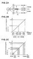
- Figs. 2A through 2C illustrate the action of the accelerator lever 22 employed in this first preferred embodiment of the invention.
- the accelerator lever 22 is a control lever which provides forward, reverse and stop control with a single lever and with which it is also possible to switch continuously from a low speed to a high speed in either forward or reverse.
- the position of this accelerator lever 22 is monitored by an accelerator potentiometer 26.
- Fig. 2B is a graph showing the relationship between the position of the accelerator lever 22 and the output of the accelerator potentiometer 26, and shows that with the voltage output range of the accelerator potentiometer 26 made 0 to +5V, 0V has been allocated to reverse full speed; +2.5V to neutral (stop); and +5V to forward full speed.
- Fig. 2C is a graph obtained by generalizing Fig. 2B and processing it for the purposes of the control of this preferred embodiment.
- 0V is allocated to reverse full speed (horizontal axis);
- Vn vertical axis
- Vmax vertical axis
- forward full speed horizontal axis
- control of this preferred embodiment is carried out in the regions between V1 and V2 and between V3 and V4 on the vertical axis in Fig. 2C .
- Fig. 3 is an enlarged view in the direction of the arrow 3 in Fig. 1 , showing the left and right speed control levers 23L, 23R.
- the left and right control handles 25L, 25R have at their ends the respective left and right grips 30L, 30R.
- the left and right speed control levers 23L, 23R are provided alongside and below the respective grips 30L, 30R and are so mounted on the control handles 25L, 25R by way of left and right hinge pins 31L, 31R that they can swing up and down.
- Arms 32L, 32R of brake potentiometers 27L, 27R are swung by the left and right speed control levers 23L, 23R.
- the left and right speed control levers 23L, 23R are urged to the position shown with a solid line by compression springs 33L, 33R. They move to a position shown with a broken line when gripped by the driver.
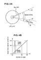
- Figs. 4A and 4B illustrate the action of the brake potentiometers 27L, 27R of this first preferred embodiment.
- Fig. 4A is an enlarged view of one of the brake potentiometers 27L, 27R.
- the arms 32L, 32R of the brake potentiometers 27L, 27R move over a range of from a position [1] through a position [2] to a position [3].
- the position [1] will be called the 'no braking point' at the beginning of the movement range;
- the position [2] will be called the full braking point', part-way through the movement range;
- the position [3] will be called the 'movement range end point'.
- the horizontal axis shows the pivot angle of the arm 32L or 32R of the brake potentiometer, i.e. the distance moved by the respective speed control lever
- the vertical axis shows the brake potentiometer output.
- 0 volts on the vertical axis is assigned to the no braking point [1] on the horizontal axis
- Vm volts on the vertical axis is assigned to the full braking point [2] on the horizontal axis
- for example 5.0 volts is assigned to the movement range end point [3] on the horizontal axis.
- Vm is a voltage satisfying 0 ⁇ Vm ⁇ 5.0, and is set to for example 1.5 volts, 2.0 volts or 2.5 volts.
- the range 0 to Vm volts on the vertical axis is a braking control range
- the range Vm to 5.0 volts on the vertical axis is a turning control range.
- Fig. 4A also, from position [1] (the start point of the movement range of the lever) to position [2] (part-way through the movement range of the lever) corresponds to braking control and from position [2] (part-way through the movement range of the lever) to position [3] (the end point of the movement range of the lever) corresponds to turning control.
- Fig. 5 is a control system view of an electric vehicle (first preferred embodiment) according to the invention.
- a left brake driver 28L brake-controls the left brake 17L. That is, as will be further discussed later, between [1] and [2] on the horizontal axis in Fig. 4B , a level of braking is changed proportionally in correspondence with the position of the left speed control lever 23L, or specifically the degree of gripping of the left speed control lever 23L.
- a right brake driver 28R brake-controls the right brake 17R. That is, as will be further discussed later, between [1] and [2] on the horizontal axis in Fig. 4B , a level of braking is changed proportionally in correspondence with the position of the right speed control lever 23R, or specifically the degree of gripping of the right speed control lever 23R.
- the control unit 24 takes in the output voltage ACCV of the accelerator potentiometer 26 and the output voltages BKLV, BKRV of the left and right brake potentiometers 27L and 27R, generates a left motor control value TG2L and a right motor control value TG2R in accordance with a control flow which will be further discussed later with reference to Fig. 14 and Fig. 15 , and controls the left and right electric motors 13L, 13R by way of left and right motor drivers 29L, 29R.
- Fig. 6 is an operation flow chart for the left and right speed control levers of an electric vehicle (first preferred embodiment) according to the invention.
- ST02 If the determination of ST01 is YES, it is checked that the vehicle speed is zero or very low. V0 means a very low speed such that even a sharp turn is possible. If the vehicle speed is above V0, processing proceeds to ST03.
- ST03 The control unit performs speed-reducing control and lowers the vehicle speed. This speed-reducing control continues until ST02 is cleared.
- ST08 When the determination of ST07 is YES, it is checked that the vehicle speed is zero or very low. If the vehicle speed is equal to or greater than the very low speed V0, processing proceeds to ST09.
- ST09 The control unit carries out speed-reducing control to lower the vehicle speed. This speed-reducing control continues until ST08 is cleared.
- a constant value (fixed value) can be employed or a variable value can be employed.
- a variable value may for example be made a speed proportional to the position of the accelerator lever 22 shown in Fig. 2A , that is, to the accelerator potentiometer output. If this is done, during work being carried out at a high speed sharp turning is effected at a high speed and during work being carried out at a low speed sharp turning is effected at a low speed, so that turning is effected which corresponds to the work mode.
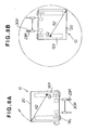
- Figs. 7A through 7C are views illustrating spot turning (turning in counter-rotation mode) in the present invention (first preferred embodiment), and show the example of a right spot turn.
- Fig. 7B shows the electric dolly 10 having turned to the right through 90°. The electric dolly 10 continues to turn to the right.
- Fig. 7C shows the electric dolly 10 having turned through 180° to the right from the state shown in Fig. 7A . It can be seen that the turning area is contained within a circle of radius R1. Minimizing the turning area like this is the object of a spot turn. By operating the right speed control lever 23R at any time, the driver can execute a right spot turn. The case of making a left spot turn is the same.
- the right speed control lever 23R is gripped to the full braking point ([2] in Fig. 4A ) or to immediately before the full braking point. This stops the right crawler 16R. However, because the left crawler 16L continues to crawl (in this example, forward), the electric dolly 10 starts to turn to the right.
- the turning center G2 at this time is the center of the right crawler 16R, and the turning radius R2 is the distance from the turning center G2 to the left corner of the load-carrying platform 20.
- Fig. 8B shows the electric dolly 10 having turned through 180°.
- a circle of radius R2 with the turning center G2 as its center defines the turning area.
- This circle is larger than the circle of radius R1 shown in Fig. 7C . Accordingly, it will be understood that to minimize the turning area the spot turn illustrated in Figs. 7A through 7C is best.
- a driver grips the left or right speed control lever more strongly.
- the position of the speed control lever is the position [2] in Fig. 4A
- a turn of the kind shown in Figs. 8A and 8B can be executed, and if the speed control lever is between the positions [2] and [3] in Fig. 4A a turn of the kind shown in Figs. 7A through 7C can be executed. That is, with this invention, a driver can freely make any turn from a gentle turn through a sharp turn to a spot turn (very sharp turn) just by operating the left or right speed control lever.
- left and right speed control levers 23L, 23R are provided alongside left and right grips 30L, 30R as shown in Fig. 1 and Fig. 3 , and a left brake 17L and a left electric motor 13L are controlled with the left speed control lever 23L and a right brake 17R and a right electric motor 13R are controlled with a right speed control lever 23R.
- the driver can operate the left and right speed control levers 23L, 23R while still gripping the grips 30L and 30R, the driver can operate the left and right speed control levers 23L, 23R easily just with the fingers, without moving either hand. As a result of this, because the driver can operate the left and right speed control levers 23L, 23R with a natural operating feeling (without great effort), driver fatigue is lessened.
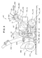
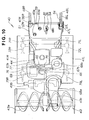
- this snow remover 40 has a transport frame 42 having left and right crawler belts 41L, 41R and mounted on this transport frame 42 so that it can swing up and down a vehicle frame 45 having a snow-clearing utility part 43 and an engine 44 for driving this snow-clearing utility part 43, the front end of the vehicle frame 45 being made to swing up and down by a frame raising/lowering mechanism 46. Also, left and right control handles 47L, 47R extend rearward (specifically, upward and rearward) from the rear part of the transport frame 42.
- the transport frame 42 and the vehicle frame 45 constitute a machine body (vehicle body) 49.
- control handles 47L, 47R are gripped to operate the snow remover 40 by an operator (not shown) walking behind the snow remover 40.
- a control panel 51, a control unit 52 and batteries 53, 53 are mounted in this order from the top between the left and right control handles 47L, 47R.
- Left and right grips 48L, 48R are attached to the ends of the left and right control handles 47L, 47R; a brake operating lever 54 is provided in the vicinity of the left grip 48L; and left and right speed control levers 56L, 56R are mounted near the left and right grips 48L, 48R.
- the snow-clearing utility part 43 is made up of an auger 43a, a blower 43b and a shooter 43c mounted on the front end of the vehicle frame 45. Power from the output shaft 65 of the engine 44 is transmitted through an electromagnetic clutch 66 to a driving pulley 67a; rotation of the driving pulley 67a is transmitted by a transmission belt 67b to a driven pulley 68b; rotation of the driven pulley 68b is transmitted by a rotating shaft 68a to the auger 43a and the blower 43b; and snow scooped up by the auger 43a is shot to far away through the shooter 43c by the blower 43b.
- the crawler belts 41L, 41R are driven by left and right electric motors 71L, 71R via left and right driving wheels 72L, 72R disposed at the rear ends of the crawler belts 41L and 41R, and left and right rolling wheels 73L, 73R are disposed at the front ends of the crawler belts 41L, 41R.
- the snow remover 40 moves under its own power by rotation of the electric motors 71L, 71R being transmitted to the left and right driving wheels 72L, 72R and driving the left and right crawler belts 41L, 41R.
- a generator pulley 75 is mounted on the output shaft 65 projecting from the engine 44, and a drive belt 77 passes around this generator pulley 75 and a pulley 76 of a charging generator 69 so that rotation of the output shaft 65 is transmitted by the drive belt 77 to the charging generator 69.
- control panel 51 Provided on the control panel 51 area raising/lowering control lever 60a for operating the frame raising/lowering mechanism 46 (shown in Fig. 9 ); a shooter control lever 60b for changing the direction of the shooter 43c; an accelerator lever 22 (the same as in the first preferred embodiment); and a throttle lever 64 for the snow-clearing utility part 43, which controls the speed of the engine 44.
- the control panel 51 also has in the vicinity of the right side control handle 47R a clutch operating button 59.
- the clutch operating button 59 operates a switch which on/off-controls the electromagnetic clutch 66.
- Fig. 11 is a control system view of an electric vehicle of this invention (second preferred embodiment).
- Mounted on the machine body 49 are the left electric motor 71L for driving the left driven wheel 72L, a left brake 74L for braking the left driven wheel 72L, the right electric motor 71R for driving the right driven wheel 72R, and a right brake 74R for braking the right driven wheel 72R.
- the left and right control handles 47L, 47R extend rearward from the machine body 49, and the left and right grips 48L, 48R are provided at the rear ends of these control handles 47L, 47R.
- the left speed control lever 56L for controlling the left brake 74L and the left electric motor 71L is mounted alongside the left grip 48L
- the right speed control lever 56R for controlling the right brake 74R and the right electric motor 71R is mounted alongside the right grip 48R.
- the left and right brakes 74L, 74R may be electromagnetic brakes which apply a braking force through an electromagnetic action; hydraulic brakes which grip a disc with a hydraulic pressure; mechanical brakes which clamp a drum with a band; regenerative brakes; or equivalent brakes of some other form or type.
- this snow remover 40 has on swing shafts 56a, 56a of the speed control levers 56L, 56R left and right brake position potentiometers 57L and 57R, and has on a swing shaft of the accelerator lever 22 an accelerator potentiometer 26 (the same as in the first preferred embodiment), and has on the left control handle 47L a brake switch 55.
- the accelerator lever 22, as in the first preferred embodiment, is a control lever which provides forward, reverse and stop control with a single lever and with which it is also possible to switch continuously from a low speed to a high speed in either forward or reverse.
- the brake switch 55 is a switch operated by the brake operating lever 54. Specifically, when the left grip 48L is gripped with the operator's left hand, the brake operating lever 54 is gripped as well and swings about a pin 54a toward the left grip 48L, whereupon the brake switch 55 assumes a break-releasing state.
- This brake operating lever 54 is a dead-man lever type parking lever.
- the left and right brake position potentiometers 57L, 57R differ from the brake potentiometers 27L, 27R of the first preferred embodiment shown in Fig. 3 only in that they have the swing shafts 56a, 56a, and otherwise are of the same construction as in the first preferred embodiment.
- Fig. 12A is an enlarged view of the speed control levers 56L, 56R and the respective brake potentiometers 57L, 57R.
- the left and right speed control levers 56L, 56R move over the range of from [1] through [2] to [3].
- the position [1] will be called the no braking point' at the beginning of the movement range; the position [2] will be called the 'full braking point', part-way through the movement range; and the position [3] will be called the 'movement range end point'.
- the reference numerals 50L and 50R denote left and right compression springs urging the left and right speed control levers 56L, 56R toward the position [1] (the position shown with solid lines).
- the springs urging the left and right speed control levers 56L, 56R toward the position [1] (the position shown with solid lines) do not have to be compression springs, and alternatively for example torsion springs can be fitted to the swing shafts 56a, 56a.
- Fig. 12B is a graph showing distance moved by the left and right speed control levers 56L, 56R on the horizontal axis and output of the brake potentiometers 57L, 57R on the vertical axis.
- 0 volts on the vertical axis is assigned to the no braking point [1] on the horizontal axis;
- Vm is a voltage satisfying 0 ⁇ Vm ⁇ 5.0, and is set to for example 1.5 volts, 2.0 volts or 2.5 volts.
- the range 0 to Vm volts on the vertical axis is a braking control range
- the range Vm to 5.0 volts on the vertical axis is a turning control range.
- Fig. 12A also, from position [1] (the start point of the movement range of the lever) to position [2] (part-way through the movement range of the lever) corresponds to braking control and from position [2] (part-way through the movement range of the lever) to position [3] (the end point of the movement range of the lever) corresponds to turning control.
- a level of braking is changed proportionally in correspondence with the position of the left speed control lever 56L, or specifically the degree of gripping of the left speed control lever 56L.
- the snow remover 40 can make a pivot turn to the left by the left crawler belt 41L stopping while the right crawler belt 41R is driven.
- the snow remover 40 can make a pivot turn in the opposite direction to that made by the electric dolly 10 in Figs. 8A and 8B .
- a level of braking is changed proportionally in correspondence with the position of the right speed control lever 56R, or specifically the degree of gripping of the right speed control lever 56R.
- the snow remover 40 can make a pivot turn to the right by the right crawler belt 41R stopping while the left crawler belt 41L is driven.
- the snow remover 40 can make a pivot turn in the same direction as that made by the electric dolly 10 in Figs. 8A and 8B .
- control unit 52 takes in the output voltage ACCV of the accelerator potentiometer 26 and controls (the speeds and directions of) the left and right electric motors 71L, 71R by way of the left and right motor drivers 29L, 29R (the same as in the first preferred embodiment).
- the method for controlling the left and right electric motors 71L, 71R and the left and right brakes 74L, 74R when the left and right speed control levers 56L, 56R are operated is the same as that shown by the flow chart of Fig. 6 discussed in the first preferred embodiment.
- left and right speed control levers 56L, 56R are provided alongside left and right grips 48L, 48R and a left brake 74L and a left electric motor 71L are controlled with the left speed control lever 56L and a right brake 74R and a right electric motor 71R are controlled with a right speed control lever 56R.
- the driver can operate the left and right speed control levers 56L, 56R while still gripping the grips 48L and 48R, the driver can operate the left and right speed control levers 56L, 56R easily just with the fingers, without moving either hand. As a result of this, because the driver can operate the left and right speed control levers 56L, 56R with a natural operating feeling (without great effort), driver fatigue is lessened.
- an electric vehicle according to the invention may alternatively be some other utility vehicle such as a mowing machine, a dozer or a cultivator, and there is no particular restriction on the type of the electric vehicle.
- the method of controlling the left and right electric motors and the left and right brakes is not limited to this. In short, any method by which it is possible to control the left and right electric motors and the left and right brakes so that the vehicle can change direction and turn when the left and right speed control levers are operated will suffice.
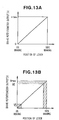
- Figs. 13A and 13B are graphs showing the braking control range of the speed control lever shown in Fig. 4A and showing the relationship between the position of the lever shown in Fig. 4B and the output of the respective brake potentiometer 27L or 27R.
- Fig. 13A shows that with the output range of the brake potentiometers 27L, 27Rmade 0 to Vm volts, 0 volts has been assigned to 0% braking and +Vm volts has been assigned to 100% braking (full braking).
- Vm is for example 1.5 volts, 2.0 volts or 2.5 volts.
- Fig. 13B is a graph obtained by generalizing Fig. 13A and processing it for the purposes of the control of this invention, and shows 0 volts assigned to 0% braking and Vmax volts assigned to 100% braking.
- Figs. 14A and 14B show a control flow for the region V5 to V6 on the vertical axis of Fig. 13B in the control unit 24 shown in Fig. 5 .
- this single control flow is divided between Figs. 14A and 14B .
- ST22 It is determined whether or not the accelerator angle ACCV read in is greater than a neutral voltage Vn. As shown in Fig. 2C , an accelerator angle ACCV greater than the neutral voltage Vn can be regarded as 'forward' and an accelerator angle ACCV less than the neutral voltage Vn can be regarded as 'reverse'. When the determination is YES then processing proceeds to ST23f, and when it is NO then processing proceeds to ST23r.
- ST23f If the determination of ST22 is YES, it is determined whether or not the accelerator angle ACCV is within the voltage range V3 to V4 shown in Fig. 2C . As shown in Fig. 2C the voltage range V3 to V4 is a control range and voltages outside this range are in a non-control range. Accordingly, if the determination is NO, processing ends.
- ST23r If the determination of ST22 is NO, it is determined whether or not the acceleration angle ACCV is in the voltage range V1 to V4. As shown in Fig. 2C , the voltage range V1 to V2 is a control range, and voltages outside this range are in a non-control range. Accordingly, if the determination is NO, processing ends.
- acceleration percentage ACC% (ACCV-V1)/(V2-V1)
- ST25 An acceleration percentage ACC% is determined on the basis of ST24f or ST24r.
- ST26L The left brake angle (the output of the left brake potentiometer) BKLV is read in.
- ST27L It is checked whether or not the BKLV read in is in the voltage range V5 to V6.
- the voltage range V5 to V6 is the control range, and voltages outside this range are in a non-control range; therefore, if the determination is NO, processing ends.
- ST26R The right brake angle (the output of the right brake potentiometer) BKRV is read in.
- ST27R It is checked whether or not the BKRV read in is in the voltage range V5 to V6.
- the voltage range V5 to V6 is the control range, and voltages outside this range are in a non-control range; therefore, if the determination is NO, processing ends.
- the left brake angle like this when determining the voltage for controlling the left motor. However, if the right brake angle is large, it is desirable to lower the left motor control voltage more. If on the other hand the right brake angle is small, its influence on the left motor can be ignored.
- BKR% is the value obtained in ST28R.
- the right brake angle BKR% will be multiplied by ACC%. And because when BKR% is directly added to BKL% the influence of the right brake angle BKR% becomes too strong, it will be multiplied by a coefficient p of 0.3 to 0.5.
- TG2L Vmax ⁇ ACC% ⁇ ⁇ 1-(BKL%+pxBKR% ⁇ ACC%) ⁇
- ST29R and ST30R are the same as ST29L and ST30L but with the L replaced with R and hence, the explanation thereof is omitted.
- accelerator levers and speed control levers do not have to be levers in a narrow sense, and may alternatively be dial switches, sliding switches or any other means by which it is possible to set a value manually.
- Electric motor control pertaining to a third preferred embodiment of the invention will now be described, on the basis of Fig. 15 and Figs. 16A through 16C .
- ST21 through ST31L and ST31R of the flow chart shown in Figs. 14A and 14B are control flows good for normal control, and generally the electric motors are controlled directly on the basis of the accelerator angle.
- electric motor control pertaining to this third preferred embodiment for example in control of the left electric motor, when the left brake angle is large the left electric motor control value is lowered, and when the right brake angle is large this is also taken into account and the left motor control value is lowered further. And the same control is carried out for the right electric motor. As a result, the waste of rotating an electric motor at a high speed while applying a brake is avoided.
- Fig. 15 is a system view corresponding to Fig. 5 , and differs from Fig. 5 in that there are provided speed detectors for detecting the speeds NL of the left electric motor 13L.
- the other construction elements are the same as those shown in Fig. 5 and have been assigned the same reference numerals as in Fig. 5 and hence, the explanation thereof is omitted.
- Figs. 16A through 16C show a sequence of control flow pertaining to the third preferred embodiment. For convenience, this single control flow has been divided between Figs. 16A , 16B and 16C .
- the control flow shown in Fig. 16A is the same as the control flow shown in Fig. 14A
- the control flow shown in Fig. 16B is the same as the control flow shown in Fig. 14B ; accordingly, the same step numbers have been assigned as in Figs. 14A and 14B and a duplicate explanation of Figs. 16A and 16B will not be given.
- BKLV is the left brake angle read in at ST26L shown in Fig. 16A
- BKRV is the right brake angle read in at ST26R.
- ST33 To check whether or not the left and right brakes are the same or almost the same, a brake threshold value Bstd below which the left and right braking angles can be regarded as substantially the same is predetermined. Then, it is determined whether or not the braking difference ⁇ BK obtained in ST32 is less than the threshold value Bstd. If the determination is NO, then because there is a difference between the left and right braking angles, the processing ends.
- ST34 If the determination of ST33 is YES, then because the left and right braking angles are essentially the same, for control to proceed further the speeds NL, NR (see Fig. 15 ) of the left and right electric motors are read in.
- a speed difference threshold value Nstd corresponding to the average Nmean obtained in ST35 is determined from the graph (a) shown in Fig. 16C .
- ST38 It is checked whether the speed difference ⁇ N obtained in ST37 is above the speed difference threshold value Nstd. If NO, then there is no great speed difference between the left and right electric motors. That is, because there is no risk of the vehicle turning even when left, control ends. In ST33 the brake angle difference was checked; however, the brake angle is not completely linked to the speed of the electric motor. Therefore, here the speed difference between the left and right electric motors is checked again.
- ST40 If the determination of ST39 is YES (the left motor speed NL > the right motor speed NR), by speed-reducing control of the left electric motor (reducing the power supplied to the left electric motor) the speeds of the left and right electric motors are made substantially the same. By this means the straight-forward characteristic of the electric vehicle can be improved.
- ST41 If the determination of ST39 is NO (the left motor speed NL ⁇ the right motor speed NR), the speeds of the left and right electric motors are made the same by speed-reducing control of the right electric motor (reducing the power supplied to the right electric motor). By this means also the straight-forward characteristic of the electric vehicle can be improved.
- Fig. 17 shows a variation of the control flow shown in Fig. 16B , in which ST30L and ST30R of Fig. 16B are dispensed with.
- ST31L of Fig. 17 a left motor control value TG1L is determined and in ST31R a right motor control value TG1R is determined.
- ST29L and ST29R are the same as in Fig. 14B and therefore will not be explained again here.
- the control flow shown in Fig. 17 is extremely simple.
- a fourth preferred embodiment of an electric vehicle according to the invention having an engine-driven utility part at the front of an electric vehicle of the kind discussed above, will now be described.
- FIG. 18 shows an electrically-propelled utility machine according to a fourth preferred embodiment.
- an electrically-propelled snow-clearer 100 serving as an example of an electrically propelled utility machine has left and right electric motors 113L, 113R powered by a battery (not shown) mounted on a vehicle body frame (vehicle body) 111.
- the electric motors 113L, 113R are rotationally driven by left and right drive shafts 114L, 114R.
- Left and right crawlers 116L, 116R are driven by driven wheels 115L, 115R mounted on the ends of these drive shafts 114L, 114R.
- the left and right driven wheels 115L, 115R are braked by the operation of left and right brakes 117L, 117R.
- a machine platform 120 is provided on the vehicle body frame 111.
- a control panel 121 is provided on the rear of the machine platform 120. This control panel 121 has a single accelerator lever 122 and a single throttle lever 125.
- Left and right operating handles 112L, 112R extend rearward from the rear of the control panel 121.
- Left and right grips 130L, 130R are provided at the rear ends of the left and right operating handles 112L, 112R.
- a left speed control lever 123L for controlling the left brake 117L and the left electric motor 113L is provided alongside the left grip 130L.
- a right speed control lever 123R for controlling the right brake 117R and the right electric motor 113R is provided alongside the right grip 130R.
- a driver does not ride the vehicle but walks behind it and advances, reverses, turns and stops it by operating the levers on the control panel 121 (including the accelerator lever 122, the throttle lever 125 and the left and right speed control levers 123L, 123R).
- a blower 134 and an auger 135, constituting utility tools, are driven by an engine 131 serving as a drive source.
- the engine 131 is mounted on the machine platform 120, and rotationally drives the blower 134 and the auger 135 by way of a clutch 132 and a tool shaft 133. Adjustment of the speed of the engine 131 is carried out by means of the throttle lever 125.
- the reference number 136 denotes an auger housing, and 137 a snow-throwing chute.
- the left and right electric motors 113L, 113R, the left and right driven wheels 115L, 115R and the left and right brakes 117L, 117R constitute a 'transit system' of the electrically-propelled snow-clearer 100.
- This transit system propels forward and backward and turns the electrically-propelled snow-clearer 100.
- the engine 131, the clutch 132, the blower 134 and the auger 135 make up a 'utility system'. This utility system performs snow-clearing work.
- the reference number 124 denotes a control unit, and this control unit 124 controls en bloc the left and right electric motors 113L, 113R and the left and right brakes 117L, 117R on the basis of the positions of the accelerator lever 122 and the left and right speed control levers 123L, 123R.
- the left and right brakes 117L, 117R may be electromagnetic brakes which apply a braking force through an electromagnetic action; hydraulic brakes which grip a disc with a hydraulic pressure; mechanical brakes which clamp a drum with a band; regenerative brakes; or equivalent brakes of some other form or type.
- Figs. 19A and 19B are views illustrating the working principle of the clutch shown in Fig. 18 .
- the clutch 132 has a drive pulley 138 attached to the output shaft of the engine a driven pulley 139 attached to the tool shaft 133; a belt 141 passing around these pulleys 138, 139; and a clutch cylinder 142 for tensioning and loosening the belt 141.
- a piston rod 143 of the clutch cylinder 142 is protruded, the belt 141 is tensioned, whereupon the clutch 132 assumes an ON-state and power is transmitted from the drive pulley 138 to the driven pulley 139.
- the action of the accelerator lever 122 used in this preferred embodiment, shown in Fig. 18 , is the same as that of the accelerator lever 22 of the first preferred embodiment, shown in Figs. 2A through 2C , and accordingly will not be explained again here.
- a left brake driver 128L brakes the left brake 117L.
- the reference number 147 denotes a speed detector for detecting the speed of the engine 131.
- the control unit 124 takes in the output voltage ACCV of an accelerator potentiometer 126, the output voltages BKLV, BKRV of the left and right brake potentiometers 127L and 127R, and the engine speed Ne, and in accordance with a control flow which will be explained later generates a left control voltage TG3L and a right control voltage TG3R and controls the left and right electric motors 113L, 113R by way of left and right motor drivers 129L, 129R.
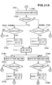
- Figs. 21A through 21C show a single control flow for the electrically-propelled utility machine of this fourth preferred embodiment. For convenience, this single control flow has been divided between Figs. 21A , 21B and 21C .
- the control flow shown in Fig. 21A is the same as the control flow shown in Fig. 14A , and therefore will not be explained again here.
- the control flow shown in Fig. 21B is the same as the control flow shown in Fig. 14B without ST31L and ST31R, and accordingly the same numbers have been assigned as in Fig. 14B and no duplicate explanation will be given here.
- ST51 It is determined whether or not the clutch is ON. If the determination is NO, i.e. if the clutch is OFF, because snow-clearing work is not being carried out, the subsequent control is unnecessary and processing ends.
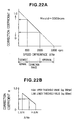
- Fig. 22B is a graph obtained by generalizing Fig. 22A .
- the H ⁇ N shown on the horizontal axis is an upper threshold value corresponding to a speed difference ⁇ Ne of 2000rpm, and L ⁇ N is a lower threshold value corresponding to a speed difference ⁇ Ne of 800rpm.
- the correction coefficient ⁇ is applied to the left and right motor control values.
- ⁇ is a coefficient greater than 0 and less than 1.0.
- a measure is taken such as generating a warning signal indicating abnormality or stopping the engine.
- ST59L The left motor control value TG2L obtained in ST30L, shown in Fig. 21B , is multiplied by ⁇ .
- ST59R The right motor control value TG2R obtained in ST30R, shown in Fig. 21B , is multiplied by ⁇ .
- ST60L A left motor control value TG3L is set, and the left electric motor is run on the basis of this left motor control value TG3L.
- ST60R A right motor control value TG3R is set, and the right electric motor is run on the basis of this right motor control value TG3R.
- the engine 131 When the speed of the engine 131 has changed, the engine 131 can be automatically restored to a predetermined speed by the control unit 124 and the throttle driver 145. At this time, the aperture change of the throttle valve 146, which opens and closes automatically in accordance with the load on the engine, can be utilized. That is, the control flow of Fig. 21C can be executed using a sudden change in the aperture of the throttle valve 146 instead of a sudden fall in the speed of the engine.
- the electrically-powered utility machine of this fourth preferred embodiment when a large load acts on the utility tool, the speed of the engine driving the utility tool falls sharply. When this happens, the outputs of the left and right electric motors are lowered and the transit speed of the machine is reduced. Normally, the electric motors are controlled directly on the basis of the accelerator angle. However, in control of the left electric motor, when the left brake angle is large, the left motor control value is lowered, and when the right brake angle is large this is also taken into account and the left motor control value is lowered further. And by this kind of control being carried out, the operator can freely control the direction of transit of the vehicle. That is, the speed of transit of the vehicle can be made to correspond to the load on the utility tool.
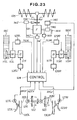
- Fig. 23 shows an example of a variation of the control system of the electrically-propelled snow-clearer 100 of the fourth preferred embodiment shown in Fig. 20 .
- an intake pressure sensor 148 for detecting the intake pressure as air is taken in to the engine 131 from the intake pipe 144 shown in Fig. 20 through the throttle valve 146. That is, the control unit 124 shown in Fig.
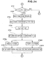
- Fig.24 ST61 It is determined whether or not the clutch is ON. If the determination is NO, i.e. the clutch is OFF, because snow-clearing work is not being carried out, the subsequent control is unnecessary and processing ends.
- ST62 If the determination in ST61 is YES, the intake pressure g1 of the engine 131 is read in by the intake pressure sensor 148.
- ST63 After a time t from when the engine intake pressure g1 was read in by ST62, the engine intake pressure is read in again. This will be written g2.
- the time t is a short time.
- the cylinders and pistons of the engine act like a reciprocating pump, and it will be supposed that, as a result of an intake valve opening and a piston descending, the intake negative pressure has fallen to g1.
- an excessive force (load) acts on the crankshaft of the engine, the rate of descent of the piston falls, and the pump action weakens, and as a result the intake negative pressure only falls to g2 (g2>g1).
- the difference g2-g1 will be called the intake pressure difference ⁇ g.
- a correction coefficient ⁇ corresponding to the intake pressure difference ⁇ g is set with reference to the graph of Fig. 26 .
- ST66L The left motor control value TG2L obtained in ST30L of the control flow shown in Fig. 21B is multiplied by ⁇ .
- ST66R The right motor control value TG2R obtained in ST30R of the control flow shown in Fig. 21B is multiplied by ⁇ .
- ST67L A final left motor control value TG3L is set, and the left electric motor is run on the basis of this left motor control value TG3L.
- ST67R A final right motor control value TG3R is set, and the right electric motor is run on the basis of this right motor control value TG3R.
- the accelerator levers and speed control levers referred to in the preferred embodiments and variations thereof described above do not have to be levers in a narrow sense, and may alternatively be dial switches, sliding switches or any other means by which it is possible to set a value manually.
- an electrically-propelled utility machine according to the invention may alternatively be some other utility vehicle such as a mowing machine, a dozer or a cultivator, and there is no particular restriction on the type of the utility vehicle.
- An electric vehicle (10, 100) has left and right speed control levers (23L, 123L, 23R, 123R) provided alongside left and right grips (30L, 130L, 30R, 130R) provided at the ends of left and right control handles (25L, 112L, 25R, 112R).
- the electric vehicle also has left and right electric motors (13L, 113L, 13R, 113R) for driving left and right driven wheels (15L, 115L, 15R, 115R) and left and right brakes (17L, 117L, 17R, 117R) for braking the left and right driven wheels.
- the left brake and the speed of the left electric motor are controlled with the left speed control lever
- the right brake and the speed of the right electric motor are controlled with the right speed control lever, and a driver can execute changes of direction and pivot turns and spot turns while holding the vehicle in a good attitude with the left and right grips.
Landscapes
- Engineering & Computer Science (AREA)
- Transportation (AREA)
- Mechanical Engineering (AREA)
- Chemical & Material Sciences (AREA)
- Combustion & Propulsion (AREA)
- Automation & Control Theory (AREA)
- Power Engineering (AREA)
- Electric Propulsion And Braking For Vehicles (AREA)
- Non-Deflectable Wheels, Steering Of Trailers, Or Other Steering (AREA)
- Train Traffic Observation, Control, And Security (AREA)
- Vehicle Body Suspensions (AREA)
Claims (9)
- Fahrtsteuerungsverfahren für ein Elektrofahrzeug, welches einen linken und einen rechten Elektromotor (13L, 113L, 13R, 113R) zum Antreiben eines linken und eines rechten Abtriebsrads (15L, 115L, 15R, 115R) aufweist und eine linke und eine rechte Bremse (17L, 117L, 17R, 117R) zum Einstellen der Drehzahlen linken und des rechten Abtriebsrads aufweist,
dadurch gekennzeichnet, daß das Verfahren die Schritte umfaßt:Einsetzen der Positionen eines Beschleunigungshebels (22, 122) und eines linken und eines rechten Geschwindigkeitssteuerungshebels (23L, 123L, 23R, 123R), welche durch einen Bediener gesteuert werden, als Beschleunigungshebelwinkel, linker Bremshebelwinkel und rechter Bremshebelwinkel;Umwandeln des Beschleunigungshebelwinkels, des linken Bremshebelwinkels und des rechten Bremshebelwinkels in einen Beschleunigungs-Prozentwert, einen linken Brems-Prozentwert und einen rechten Brems-Prozentwert;Erhalten eines korrigierten linken Brems-Prozentwerts durch Abstimmen des linken Brems-Prozentwerts auf den Einfluß des rechten Brems-Prozentwerts, Erhalten eines linken Motorsteuerwerts durch Korrigieren des Beschleunigungs-Prozentwerts mit dem korrigierten linken Brems-Prozentwert und Steuern des linken Elektromotors mit dem linken Motorsteuerwert; undErhalten eines korrigierten rechten Brems-Prozentwerts durch Abstimmen des rechten Brems-Prozentwerts auf den Einfluß des linken Brems-Prozentwerts, Erhalten eines rechten Motorsteuerwerts durch Korrigieren des Beschleunigungs-Prozentwerts mit dem korrigierten rechten Brems-Prozentwert und Steuern des rechten Elektromotors mit dem rechten Motorsteuerwert. - Fahrtsteuerungsverfahren nach Anspruch 1, wobei das Elektrofahrzeug ferner ein Räumgerät, einen Motor (131) zum Betreiben des Räumgeräts und eine Kupplung (132), welche in einer Kraftübertragungsstrecke von dem Motor zu dem Räumgerät vorgesehen ist, aufweisen; wobei der linke Motorsteuerwert durch Multiplizieren eines Werts, welcher durch Korrigieren des Beschleunigungs-Prozentwerts mit dem korrigierten linken Brems-Prozentwert erreicht wird, mit einem Korrekturkoeffizienten, welcher kleiner ist als einer, welcher gemäß einer Verminderung der Drehzahl des Motors, welche auftritt, wenn die Kupplung auf EIN gestellt ist, festgelegt wird, erhalten wird; und der rechte Motorsteuerwert durch Multiplizieren eines Werts, welcher durch Korrigieren des Beschleunigungs-Prozentwerts mit dem korrigierten rechten Brems-Prozentwert erreicht wird, mit einem Korrekturkoeffizienten, welcher kleiner ist als einer, welcher gemäß einer Verminderung der Drehzahl des Motors, welche auftritt, wenn die Kupplung auf EIN gestellt ist, festgelegt wird, erhalten wird.
- Fahrtsteuerungsverfahren nach Anspruch 1, wobei, wenn der linke und der rechte Bremswinkel im wesentlichen gleich sind, die Drehzahlen des linken und des rechten Elektromotors eingelesen werden und die Drehzahl desjenigen Motors aus der Gruppe des linken und des rechten Elektromotors, welcher mit der höheren Drehzahl läuft, auf die Drehzahl des Elektromotors mit der niedrigeren Drehzahl gesteuert wird.
- Fahrtsteuerungsverfahren nach Anspruch 3, wobei dann, wenn der Beschleunigungs-Prozentwert als ACC% bezeichnet wird, der linke Brems-Prozentwert als BKL% bezeichnet wird, der rechte Brems-Prozentwert als BKR% bezeichnet wird, ein Koeffizient des Einflusses auf denjenigen Motor aus der Gruppe des linken und des rechten Elektromotors, welcher betrachtet wird, durch den Brems-Prozentwert, welcher den anderen Elektromotor betrifft, als p bezeichnet wird (wobei p < 1) und der maximale Wert des Steuerwerts jedes Elektromotors als Vmax bezeichnet wird, der korrigierte linke Brems-Prozentwert gleich (BKL% + p × BKR% × ACC%) ist, der linke Motorsteuerwert TG2L gleich Vmax × ACC% × (1 - (BKL% + p × BKR% × ACC%)) ist, der korrigierte rechte Brems-Prozentwert gleich (BKR% + p × BKL% × ACC%) ist und der rechte Motorsteuerwert TG2R gleich Vmax × ACC% × (1 - (BKR% + p × BKL% × ACC%)) ist.
- Fahrtsteuerungsverfahren nach Anspruch 4, wobei das Elektrofahrzeug ferner ein Räumgerät aufweist und das Räumgerät eine Schnecke zum Verdrängen von Schnee und ein Gebläse zum Auswerfen verdrängten Schnees umfaßt.
- Fahrtsteuerungsverfahren nach Anspruch 1, wobei das Elektrofahrzeug ferner ein Räumgerät, einen Motor zum Betreiben des Räumgeräts und eine Kupplung, welche in einer Kraftübertragungsstrecke von dem Motor zu dem Räumgerät vorgesehen ist, aufweist und der linke und der rechte Elektromotor gemäß einer erfaßten Last an dem Motor gesteuert werden.
- Fahrtsteuerungsverfahren nach Anspruch 6, wobei der linke Motorsteuerwert durch Multiplizieren eines Werts, welcher durch Korrigieren des Beschleunigungs-Prozentwerts mit dem korrigierten linken Brems-Prozentwert erreicht wird, mit einem Korrekturkoeffizienten, welcher kleiner ist als einer, welcher gemäß einer Verminderung der Drehzahl des Motors, welche auftritt, wenn die Kupplung auf EIN gestellt ist, festgelegt wird, erhalten wird und der rechte Motorsteuerwert durch Multiplizieren eines Werts, welcher durch Korrigieren des Beschleunigungs-Prozentwerts mit dem korrigierten rechten Brems-Prozentwert erreicht wird, mit einem Korrekturkoeffizienten, welcher kleiner ist als einer, welcher gemäß einer Verminderung der Drehzahl des Motors, welche auftritt, wenn die Kupplung auf EIN gestellt ist, festgelegt wird, erhalten wird.
- Fahrtsteuerungsverfahren nach Anspruch 6, wobei der linke Motorsteuerwert durch Multiplizieren eines Werts, welcher durch Korrigieren des Beschleunigungs-Prozentwerts mit dem korrigierten linken Brems-Prozentwert erreicht wird, mit einem Korrekturkoeffizienten, welcher kleiner ist als einer, welcher gemäß einer Verminderung des Ansaugunterdrucks des Motors, welche auftritt, wenn die Kupplung auf EIN gestellt ist, festgelegt wird, erhalten wird und der rechte Motorsteuerwert durch Multiplizieren eines Werts, welcher durch Korrigieren des Beschleunigungs-Prozentwerts mit dem korrigierten rechten Brems-Prozentwert erreicht wird, mit einem Korrekturkoeffizienten, welcher kleiner ist als einer, welcher gemäß einer Verminderung Ansaugunterdrucks des Motors, welche auftritt, wenn die Kupplung auf EIN gestellt ist, festgelegt wird, erhalten wird.
- Fahrtsteuerungsverfahren nach einem der Ansprüche 2, 7 und 8, wobei das Räumgerät als Schnecke, welche Schnee verdrängt, und als Gebläse, welches verdrängten Schnee auswirft, betrieben wird.
Applications Claiming Priority (10)
| Application Number | Priority Date | Filing Date | Title |
|---|---|---|---|
| JP2000331549A JP3642727B2 (ja) | 2000-10-30 | 2000-10-30 | 電動車両の走行制御方法 |
| JP2000331562A JP3727528B2 (ja) | 2000-10-30 | 2000-10-30 | 電動車両の走行制御方法 |
| JP2000331562 | 2000-10-30 | ||
| JP2000331549 | 2000-10-30 | ||
| JP2000331551A JP3762213B2 (ja) | 2000-10-30 | 2000-10-30 | 電動走行作業機の走行制御方法 |
| JP2000331552A JP3674911B2 (ja) | 2000-10-30 | 2000-10-30 | 電動走行作業機の走行制御方法 |
| JP2000331552 | 2000-10-30 | ||
| JP2000331551 | 2000-10-30 | ||
| JP2001134689 | 2001-05-01 | ||
| JP2001134689A JP3872314B2 (ja) | 2001-05-01 | 2001-05-01 | 電動車両 |
Publications (3)
| Publication Number | Publication Date |
|---|---|
| EP1201488A2 EP1201488A2 (de) | 2002-05-02 |
| EP1201488A3 EP1201488A3 (de) | 2004-04-07 |
| EP1201488B1 true EP1201488B1 (de) | 2008-03-19 |
Family
ID=27531692
Family Applications (1)
| Application Number | Title | Priority Date | Filing Date |
|---|---|---|---|
| EP01125918A Expired - Lifetime EP1201488B1 (de) | 2000-10-30 | 2001-10-30 | Elektrisches Fahrzeug und zugehöriges Transportverfahren |
Country Status (5)
| Country | Link |
|---|---|
| US (1) | US6564481B2 (de) |
| EP (1) | EP1201488B1 (de) |
| CA (1) | CA2360621C (de) |
| DE (1) | DE60133253T2 (de) |
| NO (1) | NO320456B1 (de) |
Families Citing this family (29)
| Publication number | Priority date | Publication date | Assignee | Title |
|---|---|---|---|---|
| JP4497741B2 (ja) * | 2001-03-29 | 2010-07-07 | 株式会社小松製作所 | 装軌車両の操向装置 |
| US6705028B2 (en) * | 2001-09-12 | 2004-03-16 | Honda Giken Kogyo Kabushiki Kaisha | Self-propelled snowplow vehicle |
| US6734647B2 (en) * | 2001-10-30 | 2004-05-11 | Honda Giken Kogyo Kabushiki Kaisha | Working machine |
| CA2409913C (en) * | 2001-11-06 | 2011-02-15 | Honda Giken Kogyo Kabushiki Kaisha | Electric vehicle |
| US6808032B2 (en) * | 2001-12-14 | 2004-10-26 | Textron Inc. | Drive-by-wire lawn mower |
| US7143835B2 (en) * | 2003-03-17 | 2006-12-05 | Honda Motor Co., Ltd. | Walk-behind electric working machine |
| US7116065B2 (en) * | 2003-10-28 | 2006-10-03 | Honda Motor Co., Ltd. | Electric vehicle |
| JP3974570B2 (ja) * | 2003-10-28 | 2007-09-12 | 本田技研工業株式会社 | 電動車両の走行制御方法 |
| JP4113094B2 (ja) * | 2003-10-28 | 2008-07-02 | 本田技研工業株式会社 | 電動車両の走行制御方法 |
| JP4133752B2 (ja) * | 2003-11-11 | 2008-08-13 | 本田技研工業株式会社 | 作業機 |
| JP2006097586A (ja) * | 2004-09-29 | 2006-04-13 | Honda Motor Co Ltd | 運搬車 |
| JP4171467B2 (ja) * | 2005-01-20 | 2008-10-22 | 株式会社小松製作所 | 建設機械の制御モード切換装置および建設機械 |
| US7540102B2 (en) * | 2005-03-02 | 2009-06-02 | Wisconsin Engineering, Cz S.R.O. | Snow blower apparatus |
| US7493711B2 (en) * | 2005-04-26 | 2009-02-24 | Ronald Michael Gautreau | Ride-on snow blower |
| CN100548806C (zh) * | 2005-10-27 | 2009-10-14 | 中国国际海运集装箱(集团)股份有限公司 | 一种登机桥行走机构的控制方法 |
| US8235151B2 (en) * | 2007-08-14 | 2012-08-07 | Deere & Company | Return to neutral control mechanism for zero turning radius mower |
| WO2010019770A2 (en) * | 2008-08-15 | 2010-02-18 | Vermeer Manufacturing Company | Control system for a work unit |
| US20110094129A1 (en) * | 2009-10-27 | 2011-04-28 | Rowe Ryan F | Electric snow-thrower |
| JP5721256B2 (ja) | 2011-01-24 | 2015-05-20 | 本田技研工業株式会社 | 電動車両の制御装置 |
| US9944316B2 (en) * | 2012-04-24 | 2018-04-17 | Mtd Products Inc | Vehicle drive control systems and the related vehicles |
| US20150007462A1 (en) * | 2013-07-03 | 2015-01-08 | Joseph Cohen | Cordless snow thrower |
| JP6151624B2 (ja) * | 2013-10-23 | 2017-06-21 | 本田技研工業株式会社 | 除雪機 |
| JP6151625B2 (ja) * | 2013-10-23 | 2017-06-21 | 本田技研工業株式会社 | 除雪機 |
| JP6040139B2 (ja) * | 2013-10-23 | 2016-12-07 | 本田技研工業株式会社 | 除雪機 |
| NL2017010B1 (en) * | 2016-06-20 | 2018-01-04 | Matador Exploitatie B V | Electrically driven single-axle tractor |
| US10813284B2 (en) * | 2018-07-02 | 2020-10-27 | Deere & Company | Electric walk behind greens mower |
| US11214936B2 (en) | 2018-07-10 | 2022-01-04 | Venture Products, Inc. | Power unit with salt spreader and salt spreader for use therewith |
| CA3249070A1 (en) * | 2022-03-29 | 2023-10-05 | Ariens Company | INTUITIVE VARIABLE SPEED ELECTRIC STEERING |
| EP4552949A1 (de) * | 2023-11-10 | 2025-05-14 | Nanjing Chervon Industry Co., Ltd. | Handgeführte arbeitsmaschine |
Family Cites Families (10)
| Publication number | Priority date | Publication date | Assignee | Title |
|---|---|---|---|---|
| JPS50107619A (de) | 1974-01-31 | 1975-08-25 | ||
| JPS51137214A (en) | 1975-05-23 | 1976-11-27 | Japanese National Railways<Jnr> | Process for controlling a rotary snow plough train equipped with an au tomatic speed controller |
| JPS6015801B2 (ja) | 1980-08-27 | 1985-04-22 | コンペア、コンストラクシヨン、アンド、マイニング、リミテツド | 圧縮ガス作動型往復動ピストン装置 |
| US4572311A (en) * | 1982-08-20 | 1986-02-25 | Oswald Norman D | Walking beam arrangement for adverse terrain vehicle |
| US4527648A (en) * | 1983-09-16 | 1985-07-09 | Sines Thomas E | Battery-powered wheeled vehicle |
| ITMI961936A1 (it) * | 1996-09-20 | 1998-03-20 | Edi Micheletti | Mezzo di locomozione motorizzato |
| US6173799B1 (en) * | 1997-10-27 | 2001-01-16 | Honda Giken Kogyo Kabushiki Kaisha | Motor-assisted single-wheel cart |
| US6098385A (en) * | 1998-06-30 | 2000-08-08 | Honda Giken Kogyo Kabushiki Kaisha | Drive control for self-propelled power tool |
| US6273212B1 (en) * | 2000-02-12 | 2001-08-14 | Royce H. Husted | Lightweight maneuverable power chair |
| CA2351863C (en) * | 2000-07-12 | 2005-08-09 | Honda Giken Kogyo Kabushiki Kaisha | Snow removing machine |
-
2001
- 2001-10-29 US US10/021,539 patent/US6564481B2/en not_active Expired - Lifetime
- 2001-10-29 NO NO20015287A patent/NO320456B1/no not_active IP Right Cessation
- 2001-10-30 DE DE60133253T patent/DE60133253T2/de not_active Expired - Lifetime
- 2001-10-30 EP EP01125918A patent/EP1201488B1/de not_active Expired - Lifetime
- 2001-10-30 CA CA002360621A patent/CA2360621C/en not_active Expired - Lifetime
Also Published As
| Publication number | Publication date |
|---|---|
| EP1201488A3 (de) | 2004-04-07 |
| DE60133253D1 (de) | 2008-04-30 |
| US6564481B2 (en) | 2003-05-20 |
| NO20015287D0 (no) | 2001-10-29 |
| EP1201488A2 (de) | 2002-05-02 |
| CA2360621A1 (en) | 2002-04-30 |
| US20020062583A1 (en) | 2002-05-30 |
| DE60133253T2 (de) | 2008-06-26 |
| NO20015287L (no) | 2002-05-02 |
| CA2360621C (en) | 2005-05-03 |
| NO320456B1 (no) | 2005-12-05 |
Similar Documents
| Publication | Publication Date | Title |
|---|---|---|
| EP1201488B1 (de) | Elektrisches Fahrzeug und zugehöriges Transportverfahren | |
| US5743347A (en) | Electric powered small tractor | |
| EP1201487B1 (de) | Motorfahrzeug | |
| CA2485016C (en) | Electric vehicle | |
| JP3734670B2 (ja) | 除雪機 | |
| US20210031857A1 (en) | Oscillation-type vehicle | |
| US6513267B2 (en) | Snow removing machine with snow removing plate | |
| JP2005133343A (ja) | 作業機 | |
| EP1442648A1 (de) | Arbeitsgerät | |
| US6968265B2 (en) | Travel control method of electric vehicle | |
| US20070017717A1 (en) | Off-road vehicle with electromotive drive | |
| JP7730472B2 (ja) | 作業車両 | |
| JP3872314B2 (ja) | 電動車両 | |
| JP3638701B2 (ja) | 電動補助車両の補助力制御装置 | |
| JP3696543B2 (ja) | 電動車両 | |
| JP3476566B2 (ja) | パワーアシスト三輪自転車 | |
| JP3696542B2 (ja) | 電動車両 | |
| EP1172486B1 (de) | Schneeräumgerät mit Räumschild | |
| JP4458598B2 (ja) | 除雪機 | |
| JP2025145201A (ja) | 乗用芝刈機 | |
| JP3699672B2 (ja) | 電動車両 | |
| CA2162687C (en) | Electric powered small tractor | |
| JP4668714B2 (ja) | 三輪管理機 | |
| WO2025146627A1 (en) | Vehicle with two wheels aligned one behind the other on a frame in which at least the front wheel is powered by an electric motor | |
| JP2007032229A (ja) | 除雪機 |
Legal Events
| Date | Code | Title | Description |
|---|---|---|---|
| PUAI | Public reference made under article 153(3) epc to a published international application that has entered the european phase |
Free format text: ORIGINAL CODE: 0009012 |
|
| AK | Designated contracting states |
Kind code of ref document: A2 Designated state(s): AT BE CH CY DE DK ES FI FR GB GR IE IT LI LU MC NL PT SE TR |
|
| AX | Request for extension of the european patent |
Free format text: AL;LT;LV;MK;RO;SI |
|
| PUAL | Search report despatched |
Free format text: ORIGINAL CODE: 0009013 |
|
| AK | Designated contracting states |
Kind code of ref document: A3 Designated state(s): AT BE CH CY DE DK ES FI FR GB GR IE IT LI LU MC NL PT SE TR |
|
| AX | Request for extension of the european patent |
Extension state: AL LT LV MK RO SI |
|
| RIC1 | Information provided on ipc code assigned before grant |
Ipc: 7B 62D 11/04 B Ipc: 7B 60L 15/20 A |
|
| 17P | Request for examination filed |
Effective date: 20040611 |
|
| AKX | Designation fees paid |
Designated state(s): CH DE LI SE |
|
| GRAP | Despatch of communication of intention to grant a patent |
Free format text: ORIGINAL CODE: EPIDOSNIGR1 |
|
| RAP1 | Party data changed (applicant data changed or rights of an application transferred) |
Owner name: HONDA GIKEN KOGYO KABUSHIKI KAISHA |
|
| GRAS | Grant fee paid |
Free format text: ORIGINAL CODE: EPIDOSNIGR3 |
|
| GRAA | (expected) grant |
Free format text: ORIGINAL CODE: 0009210 |
|
| AK | Designated contracting states |
Kind code of ref document: B1 Designated state(s): CH DE LI SE |
|
| REG | Reference to a national code |
Ref country code: CH Ref legal event code: EP |
|
| REF | Corresponds to: |
Ref document number: 60133253 Country of ref document: DE Date of ref document: 20080430 Kind code of ref document: P |
|
| REG | Reference to a national code |
Ref country code: CH Ref legal event code: NV Representative=s name: A. BRAUN, BRAUN, HERITIER, ESCHMANN AG PATENTANWAE |
|
| REG | Reference to a national code |
Ref country code: SE Ref legal event code: TRGR |
|
| REG | Reference to a national code |
Ref country code: CH Ref legal event code: PFA Owner name: HONDA GIKEN KOGYO KABUSHIKI KAISHA Free format text: HONDA GIKEN KOGYO KABUSHIKI KAISHA#1-1, MINAMIAOYAMA 2-CHOME, MINATO-KU#TOKYO (JP) -TRANSFER TO- HONDA GIKEN KOGYO KABUSHIKI KAISHA#1-1, MINAMIAOYAMA 2-CHOME, MINATO-KU#TOKYO (JP) |
|
| PLBE | No opposition filed within time limit |
Free format text: ORIGINAL CODE: 0009261 |
|
| STAA | Information on the status of an ep patent application or granted ep patent |
Free format text: STATUS: NO OPPOSITION FILED WITHIN TIME LIMIT |
|
| 26N | No opposition filed |
Effective date: 20081222 |
|
| REG | Reference to a national code |
Ref country code: CH Ref legal event code: PCAR Free format text: NEW ADDRESS: HOLBEINSTRASSE 36-38, 4051 BASEL (CH) |
|
| REG | Reference to a national code |
Ref country code: DE Ref legal event code: R084 Ref document number: 60133253 Country of ref document: DE |
|
| PGFP | Annual fee paid to national office [announced via postgrant information from national office to epo] |
Ref country code: SE Payment date: 20191010 Year of fee payment: 19 Ref country code: DE Payment date: 20191015 Year of fee payment: 19 |
|
| PGFP | Annual fee paid to national office [announced via postgrant information from national office to epo] |
Ref country code: CH Payment date: 20191015 Year of fee payment: 19 |
|
| REG | Reference to a national code |
Ref country code: DE Ref legal event code: R119 Ref document number: 60133253 Country of ref document: DE |
|
| REG | Reference to a national code |
Ref country code: CH Ref legal event code: PL |
|
| REG | Reference to a national code |
Ref country code: SE Ref legal event code: EUG |
|
| PG25 | Lapsed in a contracting state [announced via postgrant information from national office to epo] |
Ref country code: DE Free format text: LAPSE BECAUSE OF NON-PAYMENT OF DUE FEES Effective date: 20210501 |
|
| PG25 | Lapsed in a contracting state [announced via postgrant information from national office to epo] |
Ref country code: LI Free format text: LAPSE BECAUSE OF NON-PAYMENT OF DUE FEES Effective date: 20201031 Ref country code: SE Free format text: LAPSE BECAUSE OF NON-PAYMENT OF DUE FEES Effective date: 20201031 Ref country code: CH Free format text: LAPSE BECAUSE OF NON-PAYMENT OF DUE FEES Effective date: 20201031 |