EP1201522A1 - Appareil pour estimer le coefficient de friction d'une route pour véhicule - Google Patents
Appareil pour estimer le coefficient de friction d'une route pour véhicule Download PDFInfo
- Publication number
- EP1201522A1 EP1201522A1 EP01125333A EP01125333A EP1201522A1 EP 1201522 A1 EP1201522 A1 EP 1201522A1 EP 01125333 A EP01125333 A EP 01125333A EP 01125333 A EP01125333 A EP 01125333A EP 1201522 A1 EP1201522 A1 EP 1201522A1
- Authority
- EP
- European Patent Office
- Prior art keywords
- friction coefficient
- road
- lissajou
- estimating
- vehicle
- Prior art date
- Legal status (The legal status is an assumption and is not a legal conclusion. Google has not performed a legal analysis and makes no representation as to the accuracy of the status listed.)
- Granted
Links
- 230000001133 acceleration Effects 0.000 claims abstract description 33
- 238000005516 engineering process Methods 0.000 description 12
- 238000000034 method Methods 0.000 description 7
- 238000010276 construction Methods 0.000 description 5
- 230000000694 effects Effects 0.000 description 4
- 239000011159 matrix material Substances 0.000 description 4
- 230000008569 process Effects 0.000 description 4
- 230000008859 change Effects 0.000 description 3
- 238000010586 diagram Methods 0.000 description 3
- 230000003111 delayed effect Effects 0.000 description 2
- 230000005484 gravity Effects 0.000 description 2
- 239000000725 suspension Substances 0.000 description 2
- 230000006399 behavior Effects 0.000 description 1
- 230000008901 benefit Effects 0.000 description 1
- 230000007547 defect Effects 0.000 description 1
- 238000012986 modification Methods 0.000 description 1
- 230000004048 modification Effects 0.000 description 1
- 230000004044 response Effects 0.000 description 1
Images


Classifications
-
- B—PERFORMING OPERATIONS; TRANSPORTING
- B60—VEHICLES IN GENERAL
- B60T—VEHICLE BRAKE CONTROL SYSTEMS OR PARTS THEREOF; BRAKE CONTROL SYSTEMS OR PARTS THEREOF, IN GENERAL; ARRANGEMENT OF BRAKING ELEMENTS ON VEHICLES IN GENERAL; PORTABLE DEVICES FOR PREVENTING UNWANTED MOVEMENT OF VEHICLES; VEHICLE MODIFICATIONS TO FACILITATE COOLING OF BRAKES
- B60T8/00—Arrangements for adjusting wheel-braking force to meet varying vehicular or ground-surface conditions, e.g. limiting or varying distribution of braking force
- B60T8/17—Using electrical or electronic regulation means to control braking
- B60T8/172—Determining control parameters used in the regulation, e.g. by calculations involving measured or detected parameters
-
- B—PERFORMING OPERATIONS; TRANSPORTING
- B60—VEHICLES IN GENERAL
- B60W—CONJOINT CONTROL OF VEHICLE SUB-UNITS OF DIFFERENT TYPE OR DIFFERENT FUNCTION; CONTROL SYSTEMS SPECIALLY ADAPTED FOR HYBRID VEHICLES; ROAD VEHICLE DRIVE CONTROL SYSTEMS FOR PURPOSES NOT RELATED TO THE CONTROL OF A PARTICULAR SUB-UNIT
- B60W40/00—Estimation or calculation of non-directly measurable driving parameters for road vehicle drive control systems not related to the control of a particular sub unit, e.g. by using mathematical models
- B60W40/02—Estimation or calculation of non-directly measurable driving parameters for road vehicle drive control systems not related to the control of a particular sub unit, e.g. by using mathematical models related to ambient conditions
- B60W40/06—Road conditions
- B60W40/068—Road friction coefficient
-
- G—PHYSICS
- G01—MEASURING; TESTING
- G01N—INVESTIGATING OR ANALYSING MATERIALS BY DETERMINING THEIR CHEMICAL OR PHYSICAL PROPERTIES
- G01N19/00—Investigating materials by mechanical methods
- G01N19/02—Measuring coefficient of friction between materials
-
- B—PERFORMING OPERATIONS; TRANSPORTING
- B60—VEHICLES IN GENERAL
- B60T—VEHICLE BRAKE CONTROL SYSTEMS OR PARTS THEREOF; BRAKE CONTROL SYSTEMS OR PARTS THEREOF, IN GENERAL; ARRANGEMENT OF BRAKING ELEMENTS ON VEHICLES IN GENERAL; PORTABLE DEVICES FOR PREVENTING UNWANTED MOVEMENT OF VEHICLES; VEHICLE MODIFICATIONS TO FACILITATE COOLING OF BRAKES
- B60T2210/00—Detection or estimation of road or environment conditions; Detection or estimation of road shapes
- B60T2210/10—Detection or estimation of road conditions
- B60T2210/12—Friction
-
- B—PERFORMING OPERATIONS; TRANSPORTING
- B60—VEHICLES IN GENERAL
- B60W—CONJOINT CONTROL OF VEHICLE SUB-UNITS OF DIFFERENT TYPE OR DIFFERENT FUNCTION; CONTROL SYSTEMS SPECIALLY ADAPTED FOR HYBRID VEHICLES; ROAD VEHICLE DRIVE CONTROL SYSTEMS FOR PURPOSES NOT RELATED TO THE CONTROL OF A PARTICULAR SUB-UNIT
- B60W50/00—Details of control systems for road vehicle drive control not related to the control of a particular sub-unit, e.g. process diagnostic or vehicle driver interfaces
- B60W2050/0001—Details of the control system
- B60W2050/0019—Control system elements or transfer functions
- B60W2050/0028—Mathematical models, e.g. for simulation
- B60W2050/0031—Mathematical model of the vehicle
-
- B—PERFORMING OPERATIONS; TRANSPORTING
- B60—VEHICLES IN GENERAL
- B60W—CONJOINT CONTROL OF VEHICLE SUB-UNITS OF DIFFERENT TYPE OR DIFFERENT FUNCTION; CONTROL SYSTEMS SPECIALLY ADAPTED FOR HYBRID VEHICLES; ROAD VEHICLE DRIVE CONTROL SYSTEMS FOR PURPOSES NOT RELATED TO THE CONTROL OF A PARTICULAR SUB-UNIT
- B60W2520/00—Input parameters relating to overall vehicle dynamics
- B60W2520/14—Yaw
-
- B—PERFORMING OPERATIONS; TRANSPORTING
- B60—VEHICLES IN GENERAL
- B60W—CONJOINT CONTROL OF VEHICLE SUB-UNITS OF DIFFERENT TYPE OR DIFFERENT FUNCTION; CONTROL SYSTEMS SPECIALLY ADAPTED FOR HYBRID VEHICLES; ROAD VEHICLE DRIVE CONTROL SYSTEMS FOR PURPOSES NOT RELATED TO THE CONTROL OF A PARTICULAR SUB-UNIT
- B60W2720/00—Output or target parameters relating to overall vehicle dynamics
- B60W2720/14—Yaw
-
- B—PERFORMING OPERATIONS; TRANSPORTING
- B60—VEHICLES IN GENERAL
- B60W—CONJOINT CONTROL OF VEHICLE SUB-UNITS OF DIFFERENT TYPE OR DIFFERENT FUNCTION; CONTROL SYSTEMS SPECIALLY ADAPTED FOR HYBRID VEHICLES; ROAD VEHICLE DRIVE CONTROL SYSTEMS FOR PURPOSES NOT RELATED TO THE CONTROL OF A PARTICULAR SUB-UNIT
- B60W40/00—Estimation or calculation of non-directly measurable driving parameters for road vehicle drive control systems not related to the control of a particular sub unit, e.g. by using mathematical models
- B60W40/02—Estimation or calculation of non-directly measurable driving parameters for road vehicle drive control systems not related to the control of a particular sub unit, e.g. by using mathematical models related to ambient conditions
- B60W40/06—Road conditions
- B60W40/072—Curvature of the road
-
- B—PERFORMING OPERATIONS; TRANSPORTING
- B60—VEHICLES IN GENERAL
- B60W—CONJOINT CONTROL OF VEHICLE SUB-UNITS OF DIFFERENT TYPE OR DIFFERENT FUNCTION; CONTROL SYSTEMS SPECIALLY ADAPTED FOR HYBRID VEHICLES; ROAD VEHICLE DRIVE CONTROL SYSTEMS FOR PURPOSES NOT RELATED TO THE CONTROL OF A PARTICULAR SUB-UNIT
- B60W40/00—Estimation or calculation of non-directly measurable driving parameters for road vehicle drive control systems not related to the control of a particular sub unit, e.g. by using mathematical models
- B60W40/02—Estimation or calculation of non-directly measurable driving parameters for road vehicle drive control systems not related to the control of a particular sub unit, e.g. by using mathematical models related to ambient conditions
- B60W40/06—Road conditions
- B60W40/076—Slope angle of the road
Definitions
- the present invention relates to a road friction coefficients estimating apparatus for a vehicle for estimating friction coefficients on road surfaces and more particularly to a road friction coefficients estimating apparatus capable of accurately estimating friction coefficients on road surfaces by a simple method using vehicle motion parameters such as lateral acceleration , yaw rate and the like.
- road friction coefficients are estimated based on vehicle motion parameters such as lateral acceleration, yaw rate.
- vehicle motion parameters such as lateral acceleration, yaw rate
- the applicant of the present invention proposes a technology in which road friction coefficients are estimated based on the comparison of an actual yaw rate estimated from an observer with a yaw rate calculated using a vehicle motion model on a high friction coefficient road surface and a yaw rate calculated using a vehicle motion model on a low friction coefficient road surface respectively in Japanese Patent Application No. Toku-Gan-Hei 11-217508.
- the technology has a disadvantage of taking much time for tuning.
- the low friction coefficient road surface model it is necessary to take a nonlinearity of tire into consideration and therefore the vehicle motion model becomes complicated and this is a primary cause of taking much time for tuning.
- the above technology is constituted by two vehicle motion models, the technology has a defect of complicated logic and large amount of calculations.
- the road friction coefficient estimating apparatus for a vehicle comprises an actual value estimating means for estimating an actual value of a vehicle motion parameter, a high friction coefficient road reference value estimating means for estimating a high friction coefficient road reference value of the vehicle motion parameter based on a vehicle motion model when the vehicle travels on a road surface with high friction coefficient and a road friction coefficient estimating means for forming a Lissajou's figure based on the actual value and the high friction coefficient road reference value and for estimating a road friction coefficient according to an area of the Lissajou's figure when a gradient of the Lissajou's figure is in the neighborhood of 45 degrees and for estimating a road friction coefficient according to a lateral acceleration of the vehicle when the gradient is in a range out of the neighborhood of 45 degrees.
- a road friction coefficient estimating apparatus 1 is mounted on a vehicle for estimating road friction coefficients and comprises control section 2.
- the control section 2 is connected with a front wheel steering angle sensor 3, a vehicle speed sensor 4, a lateral acceleration sensor 5 and a yaw rate sensor 6 and inputs signals of front wheel steering angle ⁇ fs , vehicle speed V s , lateral acceleration (d 2 y/dt 2 ) s , yaw rate (d ⁇ /dt) s (yaw angular velocity) from respective sensors.
- a subscript " s " is for indicating a value arisen from a sensor.
- the control section 2 estimates and outputs road friction coefficients.
- the control section 2 comprises a high friction coefficient road reference value estimating section 11, an actual value estimating section 12, a Lissajou figure processing section 13 and a road friction coefficient estimating section 14.
- the high friction coefficient road reference value estimating section 11 inputs vehicle speed V s and front wheel steering angle ⁇ fs , calculates high friction coefficient road reference yaw rate (d ⁇ /dt) H corresponding to the detected vehicle speed V s and front wheel steering angle ⁇ fs according to a vehicle motion model on the basis of an equation of vehicle motion on a road surface with high friction coefficient and outputs the high friction coefficient road reference yaw rate (d ⁇ /dt) H to the Lissajou figure processing section 13.
- the high friction coefficient road reference value estimating section 11 outputs yaw rate (d 2 ⁇ /dt 2 ) s besides the high friction coefficient road reference yawrate (d ⁇ /dt) H to the Lissajou figure processing section 13.
- the subscript " H " of parameters outputted from the high friction coefficient road reference value estimating section 11 denotes high friction coefficient road reference related parameters.
- a vehicle motion model used in the high friction coefficient road reference value estimating section 11 and the calculation of parameters will be described by reference to Fig. 2.
- I z ⁇ (d 2 ⁇ /dt 2 ) 2 ⁇ F f ⁇ L f - 2 ⁇ F r ⁇ L r
- I z is yaw moment of inertia of the vehicle
- L f , L r are distances from the center of gravity to the front and rear wheels, respectively
- (d 2 ⁇ /dt 2 ) is yaw angular acceleration.
- (d 2 y/dt 2 ) V ⁇ ((d ⁇ /dt) + (d ⁇ /dt) where V is vehicle speed; ⁇ is slip angle of a vehicle; and (d ⁇ /dt) is slip angular velocity of a vehicle.
- a high friction coefficient road reference vehicle slip angle ⁇ H and a high friction coefficient road reference yaw rate (d ⁇ /dt) H are obtained by integrating the vehicle slip angular velocity (d ⁇ /dt) H and the yaw angular acceleration (d 2 ⁇ /dt 2 ) H .
- the actual value estimating section 12 inputs vehicle speed V s , front wheel steering angle ⁇ fs , lateral acceleration (d 2 y/dt 2 ) s and yaw rate (d ⁇ /dt) s and calculates an actual yaw rate (d ⁇ /dt) 0 while actual vehicle behaviors are fed back. That is, the actual value estimating section 12 is an observer derived from the vehicle motion model.
- the actual yaw rate (d ⁇ /dt) 0 calculated in the actual value estimating section 12 is outputted to the Lissajou's figure processing section 13.
- the subscript "0" attached to the actual yaw rate (d ⁇ /dt) 0 denotes a parameter originated from the observer.
- the vehicle slip angular velocity (d ⁇ /dt) s is obtained from the formula (3) based on the lateral acceleration (d 2 y/dt 2 ) s detected by sensor and the yaw rate (d ⁇ /dt) s detected by sensor;
- C is matrix (in this embodiment, unit matrix) indicating the relationship between sensor output and state variable and K is feed-back gain matrix that can be arbitrarily established and C, K is expressed respectively as follows:
- an actual yaw rate (d ⁇ /dt) 0 and an actual vehicle slip angle ⁇ 0 are calculated by integrating thus calculated actual yaw angular acceleration (d 2 ⁇ /dt 2 ) 0 and actual vehicle slip angular velocity (d ⁇ /dt) 0 .
- an actual front wheel slip angle ⁇ f0 is calculated by substituting the actual vehicle slip angle ⁇ 0 and the actual yaw rate (d ⁇ /dt) 0 into the formula (6),respectively.
- the Lissajou figure processing section 13 inputs vehicle speed Vs, lateral acceleration (d 2 y/dt 2 ) s , high friction coefficient road reference yaw rate (d ⁇ /dt) H , high friction coefficient road reference yaw angular acceleration (d 2 ⁇ /dt 2 ) H , and actual yaw rate (d ⁇ /dt) 0 and forms a Lissajou's figure based on the high friction coefficient road reference yaw rate (d ⁇ /dt) H and the actual yaw rate (d ⁇ /dt) 0 .
- the Lissajou figure processing section 13 calculates a gradient r and an area S of of the Lissajou's figure and outputs those to the road friction coefficient estimating section 14. Further, the Lissajou figure processing section 13 calculates a steering pattern variable A ⁇ in integrating time T s which will be described hereinafter, further determines a maximum value (d 2 y/dt 2 ) MAX of lateral acceleration sensor values (d 2 y/dt 2 ) H in integrating time T s and outputs these steering pattern variable A ⁇ and maximum value (d 2 y/dt 2 ) MAX to the road friction coefficient estimating section 14.
- the integrating time Ts is defined as a time interval during which the high friction coefficient road reference yaw rate (d ⁇ /dt) H has the same sign as the actual yaw rate (d ⁇ /dt) 0 as shown in Fig. 4.
- the area S of Lissajou's figure is obtained by integrating small triangular areas.
- dt (hatched line portion of Fig.6) A ⁇ ⁇ A ⁇ 2 The reason why ⁇ A ⁇ is squared is to nonlinearize A ⁇ .
- the road friction coefficient estimating section 14 inputs gradient r of the Lissajou's figure, area S thereof. Steering pattern variable A ⁇ and maximum value(d 2 y/dt 2 ) MAX of lateral acceleration, estimates road friction coefficient and outputs it.
- the road friction coefficient estimating section 14 the road friction coefficient is estimated by two methods according to the gradient r of a Lissajou's figure.
- a threshold value which has been experimentally determined beforehand for various road surfaces with different friction coefficients.
- the value of lateral acceleration (d 2 y/dt 2 ) MAX divided by gravitational acceleration is a road friction coefficient estimating value ⁇ y .
- road friction coefficient estimating values ⁇ A or ⁇ y is an output value ⁇ out of the road friction coefficient estimating value.
- the Lissajou figure processing section 13 and the road friction coefficient estimating section 14 constitute a road friction coefficient estimating means.
- the yaw rate has a small delay with respect to the steering input when the vehicle travels on a road surface with high friction coefficient and has a large delay with respect to the steering input when the vehicle travels on a road surface with low friction coefficient. Since it is difficult to calculate the delay in real time, an area S of a Lissajou's figure (the size of the area presents the delay between two waveforms as shown in Figs. 8a and 8b) is obtained. Then, the road friction coefficient is estimated by comparing this area S with other area.
- the delay of yaw rate also changes according to driver's steering condition. That is, yaw rate tends to be delayed more, as a driver turns the steering wheel fast and tends to be delayed less, as the driver turns the steering wheel slowly. Taking notice of the pattern of delay of yaw rate with respect to the steering condition, an accurate estimation of road friction coefficient is available.
- the emergency condition of steering is expressed as a steering pattern variable A ⁇ obtained by squaring the integral of yaw angular acceleration (d 2 ⁇ /dt 2 ) H and the variable A ⁇ is used for estimating road friction coefficient.
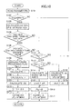
- S 101 a step (hereinafter referred to as S) 101, necessary parameters (sensor values) are read and the program goes to S102.
- the program goes to S104 wherein it is judged whether or not the high friction coefficient road reference yaw rate (d ⁇ /dt) H and the actual yaw rate (d ⁇ /dt) 0 have the same sign and those are within the integrating time T s .
- the program goes to S105 where it is judged whether or not the high friction coefficient road reference yaw rate (d ⁇ /dt) H and the actual yaw rate (d ⁇ /dt) 0 are larger than a specified value, that is, whether or not the high friction coefficient road reference yaw rate (d ⁇ /dt) H and the actual yaw rate (d ⁇ /dt) 0 are in a range containing small errors.
- the Lissajou figure processing flag Flg is set, that is, whether or not the process has finished within the integrating time T s . If the Lissajou figure processing flag Flg has been set and the process has finished within T s , the program goes to S113. On the other hand, If the Lissajou figure processing flag Flg has not been set and the process has not yet finished within T s , the program leaves the routine.
- the gradient r of the Lissajou's figure is referred to and in case where the gradient r is in the neighborhood of 45 degrees, that is, in case of 0.8 ⁇ r ⁇ 1.2, it is judged that the tire is in a linear zone and the program goes to S114 where the steering pattern variable A ⁇ is calculated based on the high friction coefficient road reference yaw angular acceleration (d 2 ⁇ /dt 2 ) H according to the formula (15) and the road friction coefficient estimating value ⁇ A is calculated based on this steering pattern variable A ⁇ and the area S of the Lissajou's figure according to the formula (16).
- the road friction coefficients estimating apparatus since a road friction coefficient can be estimated only by the outputs from the high friction coefficient road reference value estimating section 11 and the actual value estimating section 12, the road friction coefficients estimating apparatus has an advantage of that the construction of the apparatus is simple and the amount of calculation is small. Further, since in a linear zone of tire the road friction coefficient is estimated based on the change of the area S of Lissajou's figure and in a nonlinear zone of tire the road friction coefficient is estimated based on the lateral acceleration maximum value (d 2 y/dt 2 ) MAX , road friction coefficients can be estimated stably and accurately over a wide range of traveling condition. Further, since considering the degree of emergency of a vehicle driver the area S of Lissajou's figure is corrected by the steering pattern variable A ⁇ , a more accurate estimation of road friction coefficients can be performed.
Landscapes
- Engineering & Computer Science (AREA)
- Transportation (AREA)
- Mechanical Engineering (AREA)
- Physics & Mathematics (AREA)
- Automation & Control Theory (AREA)
- Chemical & Material Sciences (AREA)
- General Physics & Mathematics (AREA)
- Life Sciences & Earth Sciences (AREA)
- Mathematical Physics (AREA)
- Analytical Chemistry (AREA)
- Biochemistry (AREA)
- General Health & Medical Sciences (AREA)
- Health & Medical Sciences (AREA)
- Immunology (AREA)
- Pathology (AREA)
- Control Of Driving Devices And Active Controlling Of Vehicle (AREA)
- Regulating Braking Force (AREA)
- Steering Control In Accordance With Driving Conditions (AREA)
- Force Measurement Appropriate To Specific Purposes (AREA)
Applications Claiming Priority (2)
| Application Number | Priority Date | Filing Date | Title |
|---|---|---|---|
| JP2000332387A JP3236004B1 (ja) | 2000-10-31 | 2000-10-31 | 車両の路面摩擦係数推定装置 |
| JP2000332387 | 2000-10-31 |
Publications (2)
| Publication Number | Publication Date |
|---|---|
| EP1201522A1 true EP1201522A1 (fr) | 2002-05-02 |
| EP1201522B1 EP1201522B1 (fr) | 2005-05-25 |
Family
ID=18808600
Family Applications (1)
| Application Number | Title | Priority Date | Filing Date |
|---|---|---|---|
| EP01125333A Expired - Lifetime EP1201522B1 (fr) | 2000-10-31 | 2001-10-26 | Appareil pour estimer le coefficient de friction d'une route pour véhicule |
Country Status (4)
| Country | Link |
|---|---|
| US (1) | US6618661B2 (fr) |
| EP (1) | EP1201522B1 (fr) |
| JP (1) | JP3236004B1 (fr) |
| DE (1) | DE60110992T2 (fr) |
Cited By (5)
| Publication number | Priority date | Publication date | Assignee | Title |
|---|---|---|---|---|
| GB2435102A (en) * | 2006-02-11 | 2007-08-15 | Ford Global Tech Llc | Friction estimation for vehicle control systems |
| WO2009109279A1 (fr) * | 2008-03-06 | 2009-09-11 | Valeo Schalter Und Sensoren Gmbh | Procédé pour augmenter la précision d'un suivi de position de véhicules dans des systèmes de pilotage se fondant sur un logiciel |
| DE102014012685A1 (de) | 2014-08-25 | 2016-02-25 | Adrian Mihailescu | Verfahren zur aktiven Seitenkraft- und Reibwertschätzung |
| CN109131338A (zh) * | 2018-08-31 | 2019-01-04 | 北京新能源汽车股份有限公司 | 一种坡度检测方法、装置及电动汽车 |
| DE102018201462A1 (de) | 2018-01-31 | 2019-08-01 | Audi Ag | Verfahren zum Betreiben eines Kraftfahrzeugs sowie entsprechendes Kraftfahrzeug |
Families Citing this family (7)
| Publication number | Priority date | Publication date | Assignee | Title |
|---|---|---|---|---|
| JP3539722B2 (ja) * | 2000-11-16 | 2004-07-07 | 富士重工業株式会社 | 車両の路面摩擦係数推定装置 |
| DE602005004847T2 (de) * | 2004-08-19 | 2009-02-19 | Honda Motor Co., Ltd. | Verfahren zur Bestimmung des Reibwerts einer Strassenoberfläche und des Rutschwinkels eines Kraftfahrzeugs |
| JP5011866B2 (ja) * | 2006-01-23 | 2012-08-29 | 日産自動車株式会社 | 横すべり角推定装置、自動車、及び横すべり角推定方法 |
| JP2008109966A (ja) * | 2006-10-30 | 2008-05-15 | Bycen Inc | 動物動作を定量化する方法、動物動作定量化装置 |
| DE102016204018A1 (de) * | 2016-03-11 | 2017-09-14 | Robert Bosch Gmbh | Verfahren und Vorrichtung zur Bestimmung der Querneigung einer Fahrbahn |
| JP6494671B2 (ja) * | 2017-01-13 | 2019-04-03 | 本田技研工業株式会社 | 無段変速機の側圧制御装置 |
| JP7335713B2 (ja) * | 2019-03-28 | 2023-08-30 | 株式会社Subaru | 路面判定装置 |
Citations (3)
| Publication number | Priority date | Publication date | Assignee | Title |
|---|---|---|---|---|
| EP0444772A2 (fr) * | 1990-01-25 | 1991-09-04 | Mitsubishi Jidosha Kogyo Kabushiki Kaisha | Dispositif et procédé pour l'estimation de coefficient de friction d'une surface de chaussée |
| US5742917A (en) * | 1994-06-27 | 1998-04-21 | Fuji Jukogyo Kabushiki Kaisha | Driving torque distribution control system for vehicle and the method thereof |
| EP1072490A2 (fr) * | 1999-07-30 | 2001-01-31 | Fuji Jukogyo Kabushiki Kaisha | Appareil pour estimer le coefficient de friction d'une route |
Family Cites Families (6)
| Publication number | Priority date | Publication date | Assignee | Title |
|---|---|---|---|---|
| JP2890994B2 (ja) * | 1992-09-22 | 1999-05-17 | 三菱自動車工業株式会社 | ファジィ制御式電子制御パワーステアリング装置 |
| US5450919A (en) * | 1993-01-12 | 1995-09-19 | Mazda Motor Corporation | Differential action control system of a vehicle |
| JP3469098B2 (ja) * | 1997-09-16 | 2003-11-25 | 本田技研工業株式会社 | 電動パワーステアリング装置 |
| US6035251A (en) * | 1997-11-10 | 2000-03-07 | General Motors Corporation | Brake system control method employing yaw rate and ship angle control |
| JP2000039289A (ja) | 1998-07-22 | 2000-02-08 | Mitsubishi Heavy Ind Ltd | 気液二相流体分配器 |
| JP3525429B2 (ja) * | 1998-12-25 | 2004-05-10 | トヨタ自動車株式会社 | 操舵制御装置 |
-
2000
- 2000-10-31 JP JP2000332387A patent/JP3236004B1/ja not_active Expired - Fee Related
-
2001
- 2001-10-26 DE DE60110992T patent/DE60110992T2/de not_active Expired - Fee Related
- 2001-10-26 EP EP01125333A patent/EP1201522B1/fr not_active Expired - Lifetime
- 2001-10-30 US US09/984,425 patent/US6618661B2/en not_active Expired - Fee Related
Patent Citations (3)
| Publication number | Priority date | Publication date | Assignee | Title |
|---|---|---|---|---|
| EP0444772A2 (fr) * | 1990-01-25 | 1991-09-04 | Mitsubishi Jidosha Kogyo Kabushiki Kaisha | Dispositif et procédé pour l'estimation de coefficient de friction d'une surface de chaussée |
| US5742917A (en) * | 1994-06-27 | 1998-04-21 | Fuji Jukogyo Kabushiki Kaisha | Driving torque distribution control system for vehicle and the method thereof |
| EP1072490A2 (fr) * | 1999-07-30 | 2001-01-31 | Fuji Jukogyo Kabushiki Kaisha | Appareil pour estimer le coefficient de friction d'une route |
Cited By (6)
| Publication number | Priority date | Publication date | Assignee | Title |
|---|---|---|---|---|
| GB2435102A (en) * | 2006-02-11 | 2007-08-15 | Ford Global Tech Llc | Friction estimation for vehicle control systems |
| GB2435102B (en) * | 2006-02-11 | 2011-01-12 | Ford Global Tech Llc | Friction estimation for vehicle control systems |
| WO2009109279A1 (fr) * | 2008-03-06 | 2009-09-11 | Valeo Schalter Und Sensoren Gmbh | Procédé pour augmenter la précision d'un suivi de position de véhicules dans des systèmes de pilotage se fondant sur un logiciel |
| DE102014012685A1 (de) | 2014-08-25 | 2016-02-25 | Adrian Mihailescu | Verfahren zur aktiven Seitenkraft- und Reibwertschätzung |
| DE102018201462A1 (de) | 2018-01-31 | 2019-08-01 | Audi Ag | Verfahren zum Betreiben eines Kraftfahrzeugs sowie entsprechendes Kraftfahrzeug |
| CN109131338A (zh) * | 2018-08-31 | 2019-01-04 | 北京新能源汽车股份有限公司 | 一种坡度检测方法、装置及电动汽车 |
Also Published As
| Publication number | Publication date |
|---|---|
| DE60110992T2 (de) | 2006-05-04 |
| DE60110992D1 (de) | 2005-06-30 |
| US20020072842A1 (en) | 2002-06-13 |
| US6618661B2 (en) | 2003-09-09 |
| JP2002139417A (ja) | 2002-05-17 |
| JP3236004B1 (ja) | 2001-12-04 |
| EP1201522B1 (fr) | 2005-05-25 |
Similar Documents
| Publication | Publication Date | Title |
|---|---|---|
| US6650987B2 (en) | Road friction coefficients estimating apparatus for vehicle | |
| EP1495904B1 (fr) | Appareil et procede d'estimation d'un coefficient de frottement de la surface d'une route | |
| EP1201521B1 (fr) | Appareil pour estimer les coefficients de friction d'une route pour véhicule | |
| JP3331310B2 (ja) | 路面摩擦係数検出装置 | |
| US8244432B2 (en) | Road-surface friction-coefficient estimating device | |
| US9037376B2 (en) | Road-surface condition estimating device | |
| EP1338490B1 (fr) | Procédé de contrôle de stabilité d'un véhicule | |
| US7499826B2 (en) | Method of estimating mass for vehicle safety | |
| US6526804B2 (en) | Road friction coefficient estimating apparatus for vehicle | |
| US7751961B2 (en) | Acceleration/deceleration induced real-time identification of maximum tire-road friction coefficient | |
| US7620504B2 (en) | Road-surface condition estimating device | |
| CN111645698B (zh) | 一种重载车辆侧翻阈值自适应估计方法 | |
| EP1201522B1 (fr) | Appareil pour estimer le coefficient de friction d'une route pour véhicule | |
| JP4376549B2 (ja) | 車両の路面摩擦係数推定装置 | |
| US6543278B1 (en) | Apparatus for estimating road friction coefficient | |
| US20050082911A1 (en) | Slip regulation algorithm for an automotive vehicle using a normal force estimate and a predetermined peak wheel slip value | |
| JP2000071968A (ja) | 車両の路面摩擦係数推定装置 | |
| US20250296573A1 (en) | Methods and systems for estimating lateral adhesion of vehicle tires | |
| JP2008087548A (ja) | 旋回状態推定装置、自動車、及び旋回状態推定方法 | |
| JPH1164128A (ja) | 路面摩擦係数検出装置 | |
| WO2023210534A1 (fr) | Dispositif de commande pour véhicule | |
| JP2007106297A (ja) | 路面状態推定装置および方法、ならびに路面状態推定のためのプログラム | |
| JP2000142362A (ja) | 車両の挙動制御装置 |
Legal Events
| Date | Code | Title | Description |
|---|---|---|---|
| PUAI | Public reference made under article 153(3) epc to a published international application that has entered the european phase |
Free format text: ORIGINAL CODE: 0009012 |
|
| AK | Designated contracting states |
Kind code of ref document: A1 Designated state(s): AT BE CH CY DE DK ES FI FR GB GR IE IT LI LU MC NL PT SE TR Kind code of ref document: A1 Designated state(s): DE FR GB |
|
| AX | Request for extension of the european patent |
Free format text: AL;LT;LV;MK;RO;SI |
|
| 17P | Request for examination filed |
Effective date: 20020508 |
|
| AKX | Designation fees paid |
Free format text: DE FR GB |
|
| 17Q | First examination report despatched |
Effective date: 20030305 |
|
| GRAP | Despatch of communication of intention to grant a patent |
Free format text: ORIGINAL CODE: EPIDOSNIGR1 |
|
| GRAP | Despatch of communication of intention to grant a patent |
Free format text: ORIGINAL CODE: EPIDOSNIGR1 |
|
| RIN1 | Information on inventor provided before grant (corrected) |
Inventor name: KOGURE, MASARU,C/O FUJI JUKOGYO KABUSHIKI KAISHA |
|
| GRAS | Grant fee paid |
Free format text: ORIGINAL CODE: EPIDOSNIGR3 |
|
| GRAA | (expected) grant |
Free format text: ORIGINAL CODE: 0009210 |
|
| AK | Designated contracting states |
Kind code of ref document: B1 Designated state(s): DE FR GB |
|
| REG | Reference to a national code |
Ref country code: GB Ref legal event code: FG4D |
|
| REG | Reference to a national code |
Ref country code: IE Ref legal event code: FG4D |
|
| REF | Corresponds to: |
Ref document number: 60110992 Country of ref document: DE Date of ref document: 20050630 Kind code of ref document: P |
|
| PGFP | Annual fee paid to national office [announced via postgrant information from national office to epo] |
Ref country code: FR Payment date: 20051010 Year of fee payment: 5 |
|
| PGFP | Annual fee paid to national office [announced via postgrant information from national office to epo] |
Ref country code: DE Payment date: 20051020 Year of fee payment: 5 |
|
| PGFP | Annual fee paid to national office [announced via postgrant information from national office to epo] |
Ref country code: GB Payment date: 20051026 Year of fee payment: 5 |
|
| ET | Fr: translation filed | ||
| PLBE | No opposition filed within time limit |
Free format text: ORIGINAL CODE: 0009261 |
|
| STAA | Information on the status of an ep patent application or granted ep patent |
Free format text: STATUS: NO OPPOSITION FILED WITHIN TIME LIMIT |
|
| 26N | No opposition filed |
Effective date: 20060228 |
|
| PG25 | Lapsed in a contracting state [announced via postgrant information from national office to epo] |
Ref country code: DE Free format text: LAPSE BECAUSE OF NON-PAYMENT OF DUE FEES Effective date: 20070501 |
|
| GBPC | Gb: european patent ceased through non-payment of renewal fee |
Effective date: 20061026 |
|
| REG | Reference to a national code |
Ref country code: FR Ref legal event code: ST Effective date: 20070629 |
|
| PG25 | Lapsed in a contracting state [announced via postgrant information from national office to epo] |
Ref country code: GB Free format text: LAPSE BECAUSE OF NON-PAYMENT OF DUE FEES Effective date: 20061026 |
|
| PG25 | Lapsed in a contracting state [announced via postgrant information from national office to epo] |
Ref country code: FR Free format text: LAPSE BECAUSE OF NON-PAYMENT OF DUE FEES Effective date: 20061031 |