EP1201539B1 - Dispositif pour fabriquer et de préférence remplir et fermer des sacs en matière plastique - Google Patents
Dispositif pour fabriquer et de préférence remplir et fermer des sacs en matière plastique Download PDFInfo
- Publication number
- EP1201539B1 EP1201539B1 EP00106384A EP00106384A EP1201539B1 EP 1201539 B1 EP1201539 B1 EP 1201539B1 EP 00106384 A EP00106384 A EP 00106384A EP 00106384 A EP00106384 A EP 00106384A EP 1201539 B1 EP1201539 B1 EP 1201539B1
- Authority
- EP
- European Patent Office
- Prior art keywords
- wall
- tubular film
- film web
- jaws
- blowing air
- Prior art date
- Legal status (The legal status is an assumption and is not a legal conclusion. Google has not performed a legal analysis and makes no representation as to the accuracy of the status listed.)
- Expired - Lifetime
Links
- 229920001169 thermoplastic Polymers 0.000 title claims abstract description 6
- 239000004416 thermosoftening plastic Substances 0.000 title claims abstract description 5
- 238000011049 filling Methods 0.000 title claims description 12
- 238000003466 welding Methods 0.000 claims abstract description 17
- 238000005520 cutting process Methods 0.000 claims abstract description 12
- 238000007664 blowing Methods 0.000 claims description 15
- 238000001816 cooling Methods 0.000 claims description 15
- 239000012815 thermoplastic material Substances 0.000 claims description 4
- 238000000034 method Methods 0.000 claims description 2
- 210000000080 chela (arthropods) Anatomy 0.000 claims 1
- 239000004033 plastic Substances 0.000 abstract 1
- 238000004519 manufacturing process Methods 0.000 description 3
- 238000007711 solidification Methods 0.000 description 2
- 230000008023 solidification Effects 0.000 description 2
- 230000006978 adaptation Effects 0.000 description 1
- 238000013459 approach Methods 0.000 description 1
- 239000013590 bulk material Substances 0.000 description 1
- 230000008878 coupling Effects 0.000 description 1
- 238000010168 coupling process Methods 0.000 description 1
- 238000005859 coupling reaction Methods 0.000 description 1
- 230000007423 decrease Effects 0.000 description 1
- 239000004744 fabric Substances 0.000 description 1
- 239000000463 material Substances 0.000 description 1
- 239000002985 plastic film Substances 0.000 description 1
- 229920006255 plastic film Polymers 0.000 description 1
- 238000007789 sealing Methods 0.000 description 1
- 238000004904 shortening Methods 0.000 description 1
Images


Classifications
-
- B—PERFORMING OPERATIONS; TRANSPORTING
- B65—CONVEYING; PACKING; STORING; HANDLING THIN OR FILAMENTARY MATERIAL
- B65B—MACHINES, APPARATUS OR DEVICES FOR, OR METHODS OF, PACKAGING ARTICLES OR MATERIALS; UNPACKING
- B65B1/00—Packaging fluent solid material, e.g. powders, granular or loose fibrous material, loose masses of small articles, in individual containers or receptacles, e.g. bags, sacks, boxes, cartons, cans, or jars
- B65B1/02—Machines characterised by the incorporation of means for making the containers or receptacles
-
- B—PERFORMING OPERATIONS; TRANSPORTING
- B65—CONVEYING; PACKING; STORING; HANDLING THIN OR FILAMENTARY MATERIAL
- B65B—MACHINES, APPARATUS OR DEVICES FOR, OR METHODS OF, PACKAGING ARTICLES OR MATERIALS; UNPACKING
- B65B43/00—Forming, feeding, opening or setting-up containers or receptacles in association with packaging
- B65B43/26—Opening or distending bags; Opening, erecting, or setting-up boxes, cartons, or carton blanks
- B65B43/34—Opening or distending bags; Opening, erecting, or setting-up boxes, cartons, or carton blanks by internal pressure
- B65B43/36—Opening or distending bags; Opening, erecting, or setting-up boxes, cartons, or carton blanks by internal pressure applied pneumatically
-
- B—PERFORMING OPERATIONS; TRANSPORTING
- B65—CONVEYING; PACKING; STORING; HANDLING THIN OR FILAMENTARY MATERIAL
- B65B—MACHINES, APPARATUS OR DEVICES FOR, OR METHODS OF, PACKAGING ARTICLES OR MATERIALS; UNPACKING
- B65B43/00—Forming, feeding, opening or setting-up containers or receptacles in association with packaging
- B65B43/42—Feeding or positioning bags, boxes, or cartons in the distended, opened, or set-up state; Feeding preformed rigid containers, e.g. tins, capsules, glass tubes, glasses, to the packaging position; Locating containers or receptacles at the filling position; Supporting containers or receptacles during the filling operation
- B65B43/46—Feeding or positioning bags, boxes, or cartons in the distended, opened, or set-up state; Feeding preformed rigid containers, e.g. tins, capsules, glass tubes, glasses, to the packaging position; Locating containers or receptacles at the filling position; Supporting containers or receptacles during the filling operation using grippers
- B65B43/465—Feeding or positioning bags, boxes, or cartons in the distended, opened, or set-up state; Feeding preformed rigid containers, e.g. tins, capsules, glass tubes, glasses, to the packaging position; Locating containers or receptacles at the filling position; Supporting containers or receptacles during the filling operation using grippers for bags
-
- B—PERFORMING OPERATIONS; TRANSPORTING
- B65—CONVEYING; PACKING; STORING; HANDLING THIN OR FILAMENTARY MATERIAL
- B65B—MACHINES, APPARATUS OR DEVICES FOR, OR METHODS OF, PACKAGING ARTICLES OR MATERIALS; UNPACKING
- B65B51/00—Devices for, or methods of, sealing or securing package folds or closures; Devices for gathering or twisting wrappers, or necks of bags
- B65B51/32—Cooling, or cooling and pressing, package closures after heat-sealing
Definitions
- the invention relates to a device for manufacturing and preferably also for Filling and closing of thermoplastic bags with a Preference device for intermittently pulling a tubular film web Thermoplastic plastic and their hanging forward in vertical Direction through a cross-welding and cross-cutting device, the leading End of the tubular film web with a transverse weld seam and from this above a gripping and transporting a tube section separates.
- the object of the invention is therefore to provide a device of the initially specified type, in which the leading end of the Hose film web quickly and without fluttering by the Transverse welding and cross-cutting device in its stretched hanging Push position through, in which the end seam at the bottom Area of the transport plane of the bags to be filled.
- the through the air nozzles in the gap between the web and the blown air blown forward end of the tubular film web flows essentially with laminar flow in the feed direction and decreases the extended end of the tubular film web in stretched form with, wherein between the tubular film web and the wall, a negative pressure which creates an undesirable flutter and dodge the pushed forward end of the tubular film web prevented.
- the air blast nozzles consist of a number of Blas Kunststoffdüsen or an elongated nozzle gap.
- At least one of the jaws is directed with respect to the bottom weld Provided blowing air nozzles.
- both jaws rows of blowing air nozzles which are directed to the bottom weld.
- the Bakken conveniently do not clamp the bottom weld between them, to prevent them from sticking to the jaws.
- bags are different Size and length made and filled. Therefore, it is necessary to Distance between the cross-welding and cross-cutting device and the transport plane to change the bags to be filled and on different bag lengths adapt.
- the cooling serving jaws are therefore expediently arranged on the support of a conveyor belt conveying off the filled sacks, the format change can be raised and lowered in the machine frame is guided and stored.
- the separated bags squeezing pliers are conveniently transversely displaceable or pivotally mounted to the machine frame so that they separated Sacks to promote a stroke in the direction of the filling station.
- a second Cooling jaw pair provided, of which at least one jaw is cooled. Also this second pair of cooling jaws is expediently with the carrier of the conveyor belt or attached to a console connected thereto.
- the length of the wall to the height of the support of the conveyor belt, so changed to Bag formats, is adaptable.
- the wall of a flexible Rail consist whose lower end to the carrier or at one connected thereto Console is attached, the web between an upper deflecting rod or deflecting edge and an attachment of its other end to the machine frame placed in a loop and in the loop a weight, e.g. a Rod, is inserted.
- a weight e.g. a Rod
- the wall can also be made of each other overlapping wall sections are made, of which the upper frame held and the lower is attached to the carrier.
- the wall sections of rigid material.
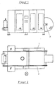
- the device shown in the drawing for manufacturing, filling, sealing and conveying bags of thermoplastic material consists of a Machine with relatively short length, in which all processing stations are arranged in a single machine frame.
- the machine frame consists of two side parts 1, 2, by usual, not Travers shown are connected together.
- the machine frame is through Plates, doors and windows, clad, so that it outwardly a handsome Looks good.
- a unwinding device 3 for a wound to a supply roll tubular film web made of thermoplastic material, in which a tubular film roll 4 is mounted.
- the withdrawn from the tubular film roll 4 tubular film web 5 is cyclically advanced by a preferred pair of rollers 6 via pulleys.
- the pendulum roller 12 is between two in Machine frame mounted levers 13 mounted, the intermittently from a pneumatic cylinder 14 pivoted out of her pivoted into her Position is pivoted.
- the feed roller pair 6 pulls over the pulley 7 expiring tubular film web 5 in the vertical direction and pushes this between a transverse welding and cross-cutting device 15 therethrough.
- This transverse welding and cross-cutting station consists of a frame-fixed jaw 16 and a pivotable Baking 17, which is supported by fixed frame mounted handlebars 18 and from a provided with a drive and hingedly connected to a handlebar 18 Rod 19 is pivoted back and forth.
- the upper part of the jaws 16, 17 is as formed the bottom welds exporting welding jaws. Below the Welding jaws is the fixed jaw 16 with a groove and the pivotable Baking 17 provided with a cutting blade 20, which in time to be separated Hose sections 21 dips into the groove.
- the tubular film web is preferably provided with gussets.
- a coupling forming carrier 24 is mounted, with an obliquely projecting Cantilever 25 is connected to the side below the opening edges the hose portions 21 engaging gripping tongs 26 are arranged, the are indicated by the gripping jaws shown.
- a Jointed rod 27 is driven by one of a geared motor 28 Crank 29 is reciprocated.
- the Grippers 32 are supported by levers 34, 35, both on a push rod 36 are hinged and with their articulation points on the push rod and the grippers form a four-joint system.
- the lever 35 is a two-armed lever whose upper lever arm 37 is mounted fixed to the frame in the manner shown.
- the push rod 36 is articulated to a two-armed frame-mounted lever 38, whose upper lever arm in the manner illustrated by a return spring 39 loaded is.
- the crank 29 is formed in the manner shown as a cam, wherein on this cam one on the lower lever arm of the two-armed Lever 37 mounted cam roller 40 is running.
- the push rod 36 is driven by its cam lever cam roller drive driven such that the gripper 32nd leading the bag section leading to holding gripper, the side of the opening areas the bag sections below the hopper 42 attack.
- a second gripper pair 43 is arranged, which after filling again pulled tight opening edges of the filled bag in the welding station 34 transferred, in the welding jaws, not shown, the tightened Close the opening edges of the bag with a transverse weld.
- the drive and deflection rollers 52, 53 of the conveyor belt 51 are at the ends a horizontal support 55 mounted in the frame-fixed guides 56 through a spindle drive 57 can be raised and lowered, wherein the drive for the spindle drive consists of a geared motor 58.
- the lower end 63 of the track 62 is connected to consoles 64 which connected to the carrier 55 of the conveyor belt 51 in the manner shown in FIG. 4 manner are.
- the web 62 runs from its lower attachment 63 via an upper fixedly held deflecting rod 65 to its frame-fixed attachment 66th Between the deflecting rod 65 and its attachment 66 is the web 62 to a Loop 67 pulled out, wherein in the loop a web 62 tautly holding Rod 68 is inserted.
- the taut portion 62 of FIG Train always to the changed sack formats by the fact that the required track length is withdrawn from the loop 67 or wanders into this.
- a gap suitable width 69 formed between the consisting of the tightly stretched film web 62 wall and the advanced by the feed rollers 6 section of the web 5 is a gap suitable width 69 formed.
- the tuyeres 61 or a blowing nozzle gap from which blowing air in the feed direction of the leading Section of the web 5 is blown into the gap 69. Due to the Narrowing in the gap, the blowing air undergoes a laminar flow, the one Suction acts on the advanced web section and thereby their Flutter prevents us from dodging. Because of the train tightening and sucking Effect of Blas Kunststoffstrom 61 can be the leading section of the Tube film web 5 with the predetermined by the feed roller pair 6 speed Lower in the direction of the console 64.
- the grippers 26 detect the section laterally below the upper opening edge, so that then the section 21 separated and at the same time on the newly formed end of the tubular film web 5, the transverse weld can be formed.
- the gripping tongs 26 promote then the upper end of the section for a tact further, so that in the transfer station 31 the attacking from above pliers 32 can take over the section.
- This fixed jaw 76 is a pivoting jaw 77 assigned to the machine cycle of a pneumatic cylinder 78 against the fixed jaw 76 is pivoted.
- the fixed jaw 76 is of Traversed channels 79, flows through the cooling air.
- the short Ver Because of the bag section 21 in the transfer station 31 takes place by the clamping the weld 60 between the jaws 76, 77 another cooling the weld 60.
Landscapes
- Engineering & Computer Science (AREA)
- Mechanical Engineering (AREA)
- Making Paper Articles (AREA)
- Containers And Plastic Fillers For Packaging (AREA)
- Supplying Of Containers To The Packaging Station (AREA)
Claims (14)
- Dispositif pour fabriquer et de préférence aussi pour remplir et fermer des sacs en matériau synthétique thermoplastique,
avec une installation de traction (6) pour la traction par intermittence d'une bande de film tubulaire (5) en matériau synthétique thermoplastique et la poussée, à l'état pendant, de celle-ci dans la direction verticale à travers une installation de soudage transversal et de coupe transversale (15) qui réalise à l'extrémité avant de la bande de film tubulaire une soudure transversale (60) et qui sépare de celle-ci au-dessus d'une installation de préhension et de transport (26) un tronçon tubulaire (21),
caractérisé en ce qu'une paroi est prévue et
en ce que sont disposées au-dessus de la paroi ou de sa zone supérieure des buses d'air de soufflage (61) orientée dans la direction de poussée de la bande de film tubulaire (5) entre la paroi et le chemin de poussée de la bande de film tubulaire (5), où la paroi (62) est disposée de telle sorte relativement au chemin de poussée qu'il est formé entre la paroi (62) et l'extrémité poussée vers l'avant de la bande de film tubulaire (5) une fente (69) dans laquelle s'écoule l'air de soufflage soufflé par les buses d'air de soufflage (61) et entraíne l'extrémité poussée vers l'avant de la bande de film tubulaire (5) sous une forme étirée. - Dispositif selon la revendication 1,
caractérisé en ce que les buses d'air de soufflage (61) sont constituées d'une rangée de buses d'air de soufflage ou d'une fente de buse allongée. - Dispositif selon la revendication 1 ou 2,
caractérisé en ce que sont prévues dans la zone d'extrémité du chemin de poussée des mâchoires (72, 73) refroidissant la soudure de fond (60). - Dispositif selon l'une des revendications 1 à 3,
caractérisé en ce que les mâchoires sont constituées d'une mâchoire fixe (70) et d'une mâchoire (72) apte à pivoter à la manière d'une pince. - Dispositif selon la revendication 3 ou 4,
caractérisé en ce qu'au moins l'une des mâchoires (70, 72) est pourvue de buses d'air de soufflage (73, 74) dirigées vers la soudure de fond (60). - Dispositif selon l'une des revendications précédentes,
caractérisé en ce que les mâchoires (70, 72) servant au refroidissement sont disposées au support (55) d'une bande de convoyage (51) évacuant les sacs remplis. - Dispositif selon la revendication 6,
caractérisé en ce que le support (55) de la bande de convoyage (51) peut être relevé et abaissé. - Dispositif selon l'une des revendications précédentes,
caractérisé en ce que des pinces sont logées d'une manière déplaçable transversalement ou d'une manière pivotante dans le bâti de machine et transportent les tronçons de sac respectivement sacs séparés à chaque fois selon un trajet cadencé. - Dispositif selon l'une des revendications précédentes,
caractérisé en ce qu'il est prévu à peu près à une distance de cadence des mâchoires de refroidissement (70, 72) une deuxième paire de mâchoires de refroidissement (76, 77) dont au moins une mâchoire (76) est refroidie. - Dispositif selon la revendication 9,
caractérisé en ce que les mâchoires (76, 77) sont fixées à une console (64) reliée au support (55) de la bande de convoyage. - Dispositif selon l'une des revendications précédentes,
caractérisé en ce que la longueur de la paroi (62) peut être adaptée à la hauteur du support (55) de la bande de convoyage (51). - Dispositif selon l'une des revendications précédentes,
caractérisé en ce que la paroi (62) est constituée d'une bande flexible dont l'extrémité inférieure est fixée au support ou à une console (64) reliée à celui-ci, et en ce que la bande (62), entre une tige de renvoi supérieure (65) ou arête de renvoi et une fixation de son extrémité inférieure (66) est formée en boucle (67) au bâti de machine, et dans la boucle, un poids, par exemple une tige (68) est placé. - Dispositif selon l'une des revendications 1 à 11, caractérisé en ce que la paroi est constituée de tronçons de paroi qui se chevauchent, dont le tronçon supérieur est solidaire du châssis, et le tronçon inférieur est fixé au support.
- Procédé pour fabriquer et de préférence aussi pour remplir et fermer des sacs en matériau synthétique thermoplastique, où une installation de traction (6) tire une bande de film tubulaire (5) en matériau synthétique thermoplastique par intermittence et la pousse, en pendant dans la direction verticale, à travers une installation de soudage transversal et de coupe transversale (15),
et lors duquel l'installation de traction (6) munit l'extrémité poussée vers l'avant de la bande de film tubulaire d'une soudure transversale (60) et sépare de celle-ci au-dessus d'une installation de préhension et de transport un tronçon tubulaire,
caractérisé en ce que l'extrémité poussée vers l'avant de la bande de film tubulaire (5) est amenée à passer devant une paroi (62) et
en ce qu'au-dessus de la paroi (62) ou dans la zone supérieure de celle-ci, des buses d'air de soufflage (61) orientées dans la direction de poussée, qui sont disposées entre la paroi (62) et le chemin de poussée, soufflent de l'air dans la fente qui est produite entre la paroi (62) et l'extrémité avant de la bande de film tubulaire (5), où l'extrémité poussée vers l'avant de la bande de film tubulaire (5) est entraínée sous une forme étirée.
Priority Applications (3)
| Application Number | Priority Date | Filing Date | Title |
|---|---|---|---|
| ES00106384T ES2251901T3 (es) | 2000-10-24 | 2000-10-24 | Dispositivo para fabricar y, preferiblemente, tambien para llenar y cerrar sacos de material sintetico termoplastico. |
| EP00106384A EP1201539B1 (fr) | 2000-10-24 | 2000-10-24 | Dispositif pour fabriquer et de préférence remplir et fermer des sacs en matière plastique |
| AT00106384T ATE313483T1 (de) | 2000-10-24 | 2000-10-24 | Vorrichtung zum herstellen und vorzugsweise auch zum befüllen und verschliessen von säcken aus thermoplastichem kunststoff |
Applications Claiming Priority (1)
| Application Number | Priority Date | Filing Date | Title |
|---|---|---|---|
| EP00106384A EP1201539B1 (fr) | 2000-10-24 | 2000-10-24 | Dispositif pour fabriquer et de préférence remplir et fermer des sacs en matière plastique |
Publications (2)
| Publication Number | Publication Date |
|---|---|
| EP1201539A1 EP1201539A1 (fr) | 2002-05-02 |
| EP1201539B1 true EP1201539B1 (fr) | 2005-12-21 |
Family
ID=8168215
Family Applications (1)
| Application Number | Title | Priority Date | Filing Date |
|---|---|---|---|
| EP00106384A Expired - Lifetime EP1201539B1 (fr) | 2000-10-24 | 2000-10-24 | Dispositif pour fabriquer et de préférence remplir et fermer des sacs en matière plastique |
Country Status (3)
| Country | Link |
|---|---|
| EP (1) | EP1201539B1 (fr) |
| AT (1) | ATE313483T1 (fr) |
| ES (1) | ES2251901T3 (fr) |
Cited By (5)
| Publication number | Priority date | Publication date | Assignee | Title |
|---|---|---|---|---|
| DE102007014892A1 (de) | 2007-03-26 | 2008-10-02 | Windmöller & Hölscher Kg | Sackabfüllverfahren an einer Form-, Fill- und Seal-Maschine |
| DE102007014890A1 (de) | 2007-03-26 | 2008-10-02 | Windmöller & Hölscher Kg | Wiegeverfahren für eine Form-, Fill- und Seal-Maschine |
| DE102010028394A1 (de) | 2010-04-29 | 2011-11-03 | Windmöller & Hölscher Kg | Verfahren und eine Vorrichtung zur Herstellung und Befüllung von Verpackungsmitteln |
| DE102011015491B3 (de) * | 2011-03-29 | 2012-06-06 | Windmöller & Hölscher Kg | Verfahren zum Querschweißen von Kunststoffschläuchen und Vorrichtung zum Formen und Schließen von Säcken |
| US10029407B2 (en) | 2014-12-04 | 2018-07-24 | Big Heart Pet, Inc. | Apparatus, processes, and systems for heat sealing |
Families Citing this family (7)
| Publication number | Priority date | Publication date | Assignee | Title |
|---|---|---|---|---|
| DE19920479B4 (de) * | 1999-05-04 | 2005-03-31 | Windmöller & Hölscher Kg | Maschine zur Bearbeitung und/oder Herstellung von Gegenständen |
| DE20206497U1 (de) | 2002-04-18 | 2002-08-14 | Union Spezial GmbH, 71696 Möglingen | Sackverschliesseinheit |
| DE20209492U1 (de) | 2002-06-19 | 2002-08-29 | Haver & Boecker, 59302 Oelde | Kühleinrichtung |
| DE102006022709A1 (de) | 2006-05-12 | 2007-11-15 | Windmöller & Hölscher Kg | Form-, Fill-, Sealmaschine sowie Verfahren zum Herstellen, Befüllen und Schließen von Säcken |
| DE102013105603B9 (de) | 2013-05-31 | 2018-03-15 | Windmöller & Hölscher Kg | Transportvorrichtung für den transport eines sackabschnitts in einer sackfüllanlage |
| DE102018206356A1 (de) * | 2018-02-19 | 2019-10-17 | Windmöller & Hölscher Kg | Fülleinrichtung und Verfahren zum Befüllen von Säcken mit jeweils einem unverschlossenen oberen Ende |
| WO2019158386A1 (fr) * | 2018-02-19 | 2019-08-22 | Windmöller & Hölscher Kg | Dispositif de remplissage et procédé permettant de remplir des sacs dotés respectivement d'une extrémité supérieure non fermée |
Family Cites Families (5)
| Publication number | Priority date | Publication date | Assignee | Title |
|---|---|---|---|---|
| FR2079851A5 (fr) * | 1970-02-16 | 1971-11-12 | Fara Pierre | |
| DE2301817C3 (de) * | 1973-01-15 | 1983-11-03 | Sieg-Rheinische Registrierwaagenfabrik "fix" Peter Steimel, 5205 Hennef | Vorrichtung mit auf einem Kreisumfang angeordneten Stationen zum Herstellen von Seitenfaltensäcken aus einem Seitenfaltenschlauch |
| DE2418228C3 (de) * | 1974-04-13 | 1978-10-05 | Haver & Boecker, 4740 Oelde | Maschine zum Herstellen und Füllen von Beuteln oder Säcken aus Kunststoff |
| DE3118866C2 (de) * | 1981-05-13 | 1984-04-12 | Haver & Boecker, 4740 Oelde | "Maschine zum Füllen und Verschließen von Säcken aus Kunststoff, vorzugsweise von Seitenfaltensäcken oder Flachsäcken" |
| DE69701180T2 (de) * | 1996-05-08 | 2000-09-14 | Payper S.A., Lleida | Selbständig arbeitende aufsackmaschine |
-
2000
- 2000-10-24 AT AT00106384T patent/ATE313483T1/de not_active IP Right Cessation
- 2000-10-24 EP EP00106384A patent/EP1201539B1/fr not_active Expired - Lifetime
- 2000-10-24 ES ES00106384T patent/ES2251901T3/es not_active Expired - Lifetime
Cited By (8)
| Publication number | Priority date | Publication date | Assignee | Title |
|---|---|---|---|---|
| DE102007014892A1 (de) | 2007-03-26 | 2008-10-02 | Windmöller & Hölscher Kg | Sackabfüllverfahren an einer Form-, Fill- und Seal-Maschine |
| DE102007014890A1 (de) | 2007-03-26 | 2008-10-02 | Windmöller & Hölscher Kg | Wiegeverfahren für eine Form-, Fill- und Seal-Maschine |
| DE102010028394A1 (de) | 2010-04-29 | 2011-11-03 | Windmöller & Hölscher Kg | Verfahren und eine Vorrichtung zur Herstellung und Befüllung von Verpackungsmitteln |
| WO2011135025A1 (fr) | 2010-04-29 | 2011-11-03 | Windmöller & Hölscher Kg | Procédé et dispositif pour fabriquer et remplir des moyens d'emballage |
| DE102010028394B4 (de) | 2010-04-29 | 2019-05-23 | Windmöller & Hölscher Kg | Verfahren und eine Vorrichtung zur Herstellung und Befüllung von Verpackungsmitteln |
| DE102011015491B3 (de) * | 2011-03-29 | 2012-06-06 | Windmöller & Hölscher Kg | Verfahren zum Querschweißen von Kunststoffschläuchen und Vorrichtung zum Formen und Schließen von Säcken |
| EP2505337A2 (fr) | 2011-03-29 | 2012-10-03 | Windmöller & Hölscher KG | Procédé de soudage transverse de tuyaux souples en matière plastique et dispositif de formage et fermeture de sacs |
| US10029407B2 (en) | 2014-12-04 | 2018-07-24 | Big Heart Pet, Inc. | Apparatus, processes, and systems for heat sealing |
Also Published As
| Publication number | Publication date |
|---|---|
| EP1201539A1 (fr) | 2002-05-02 |
| ATE313483T1 (de) | 2006-01-15 |
| ES2251901T3 (es) | 2006-05-16 |
Similar Documents
| Publication | Publication Date | Title |
|---|---|---|
| DE19920478C2 (de) | Vorrichtung zum Herstellen und vorzugsweise auch zum Befüllen und Verschließen von Säcken aus thermoplastischem Kunststoff | |
| EP1050457B1 (fr) | Dispositif pour fabriquer, remplir et fermer des sacs | |
| DE2833232C2 (de) | Vorrichtung zum Herstellen von Hemdchenbeuteln aus einer mit Seitenfalten versehenen Kunststoffschlauchfolienbahn | |
| DE3345459C2 (fr) | ||
| DE3118866C2 (de) | "Maschine zum Füllen und Verschließen von Säcken aus Kunststoff, vorzugsweise von Seitenfaltensäcken oder Flachsäcken" | |
| DE3515846C2 (fr) | ||
| US4586318A (en) | Bag forming and bagger apparatus and method | |
| DE2825722C2 (de) | Vorrichtung zum Herstellen von Beuteln oder Säcken und zu deren Ablegen in Schuppenformation | |
| EP1201539B1 (fr) | Dispositif pour fabriquer et de préférence remplir et fermer des sacs en matière plastique | |
| DE2418228C3 (de) | Maschine zum Herstellen und Füllen von Beuteln oder Säcken aus Kunststoff | |
| DE2833236C2 (de) | Vorrichtung zum Herstellen und Stapeln von Kunststoffbeuteln | |
| DE2629065B2 (de) | Vorrichtung zum automatischen Füllen und Verschließen von Säcken | |
| EP0439789B1 (fr) | Procédé et dispositif pour la fabrication, le remplissage et la fermeture de sacs | |
| DE2618690C3 (de) | Verpackungsmaschine | |
| DE2819887C2 (de) | Vorrichtung zum Herstellen einer ein Trägerband und auf diesem schuppenförmig übereinanderliegend angeordnete flache Werkstücke aufweisenden Anordnung zum Speichern der Werkstücke | |
| DE19936660C2 (de) | Vorrichtung zum Herstellen, Befüllen und Verschließen von Säcken | |
| CH396742A (de) | Vorrichtung zum Herstellen von Weichbeuteln an einer Füll- und Schliessmaschine | |
| DE2459725A1 (de) | Vorrichtung zum beschicken einer beutel- und sackfuelleinrichtung | |
| DE10217397B4 (de) | Verfahren und Vorrichtung zum Befüllen von Säcken | |
| EP0133286B1 (fr) | Machine à traiter des feuilles | |
| EP0544078B1 (fr) | Dispositif pour la séparation d'une bande, des trançons tubulaires avec des soudures transversales et les empiler | |
| EP0215269B1 (fr) | Dispositif pour la fabrication de sacs | |
| EP1667913B1 (fr) | Procede pour remplir des sacs | |
| DE1265563C2 (de) | Maschine zum Herstellen offener Kunststoffsaecke | |
| EP0916579A1 (fr) | Dispositif pour ouvrir des sacs en matière plastique |
Legal Events
| Date | Code | Title | Description |
|---|---|---|---|
| PUAI | Public reference made under article 153(3) epc to a published international application that has entered the european phase |
Free format text: ORIGINAL CODE: 0009012 |
|
| AK | Designated contracting states |
Kind code of ref document: A1 Designated state(s): AT BE CH CY DE DK ES FI FR GB GR IE IT LI LU MC NL PT SE |
|
| AX | Request for extension of the european patent |
Free format text: AL;LT;LV;MK;RO;SI |
|
| 17P | Request for examination filed |
Effective date: 20021104 |
|
| AKX | Designation fees paid |
Free format text: AT BE CH CY DE DK ES FI FR GB GR IE IT LI LU MC NL PT SE |
|
| GRAP | Despatch of communication of intention to grant a patent |
Free format text: ORIGINAL CODE: EPIDOSNIGR1 |
|
| RBV | Designated contracting states (corrected) |
Designated state(s): AT BE CH CY DK ES FI FR GB GR IE IT LI LU MC NL PT SE |
|
| REG | Reference to a national code |
Ref country code: DE Ref legal event code: 8566 |
|
| GRAS | Grant fee paid |
Free format text: ORIGINAL CODE: EPIDOSNIGR3 |
|
| GRAA | (expected) grant |
Free format text: ORIGINAL CODE: 0009210 |
|
| AK | Designated contracting states |
Kind code of ref document: B1 Designated state(s): AT BE CH CY DK ES FI FR GB GR IE IT LI LU MC NL PT SE |
|
| PG25 | Lapsed in a contracting state [announced via postgrant information from national office to epo] |
Ref country code: FI Free format text: LAPSE BECAUSE OF FAILURE TO SUBMIT A TRANSLATION OF THE DESCRIPTION OR TO PAY THE FEE WITHIN THE PRESCRIBED TIME-LIMIT Effective date: 20051221 Ref country code: IE Free format text: LAPSE BECAUSE OF FAILURE TO SUBMIT A TRANSLATION OF THE DESCRIPTION OR TO PAY THE FEE WITHIN THE PRESCRIBED TIME-LIMIT Effective date: 20051221 |
|
| REG | Reference to a national code |
Ref country code: GB Ref legal event code: FG4D Free format text: NOT ENGLISH |
|
| REG | Reference to a national code |
Ref country code: CH Ref legal event code: EP |
|
| REG | Reference to a national code |
Ref country code: IE Ref legal event code: FG4D Free format text: LANGUAGE OF EP DOCUMENT: GERMAN |
|
| PG25 | Lapsed in a contracting state [announced via postgrant information from national office to epo] |
Ref country code: SE Free format text: LAPSE BECAUSE OF FAILURE TO SUBMIT A TRANSLATION OF THE DESCRIPTION OR TO PAY THE FEE WITHIN THE PRESCRIBED TIME-LIMIT Effective date: 20060321 Ref country code: GR Free format text: LAPSE BECAUSE OF FAILURE TO SUBMIT A TRANSLATION OF THE DESCRIPTION OR TO PAY THE FEE WITHIN THE PRESCRIBED TIME-LIMIT Effective date: 20060321 Ref country code: DK Free format text: LAPSE BECAUSE OF FAILURE TO SUBMIT A TRANSLATION OF THE DESCRIPTION OR TO PAY THE FEE WITHIN THE PRESCRIBED TIME-LIMIT Effective date: 20060321 |
|
| GBT | Gb: translation of ep patent filed (gb section 77(6)(a)/1977) |
Effective date: 20060309 |
|
| REG | Reference to a national code |
Ref country code: ES Ref legal event code: FG2A Ref document number: 2251901 Country of ref document: ES Kind code of ref document: T3 |
|
| PG25 | Lapsed in a contracting state [announced via postgrant information from national office to epo] |
Ref country code: PT Free format text: LAPSE BECAUSE OF FAILURE TO SUBMIT A TRANSLATION OF THE DESCRIPTION OR TO PAY THE FEE WITHIN THE PRESCRIBED TIME-LIMIT Effective date: 20060522 |
|
| ET | Fr: translation filed | ||
| REG | Reference to a national code |
Ref country code: IE Ref legal event code: FD4D |
|
| PLBE | No opposition filed within time limit |
Free format text: ORIGINAL CODE: 0009261 |
|
| STAA | Information on the status of an ep patent application or granted ep patent |
Free format text: STATUS: NO OPPOSITION FILED WITHIN TIME LIMIT |
|
| PG25 | Lapsed in a contracting state [announced via postgrant information from national office to epo] |
Ref country code: CH Free format text: LAPSE BECAUSE OF NON-PAYMENT OF DUE FEES Effective date: 20061031 Ref country code: MC Free format text: LAPSE BECAUSE OF NON-PAYMENT OF DUE FEES Effective date: 20061031 Ref country code: LI Free format text: LAPSE BECAUSE OF NON-PAYMENT OF DUE FEES Effective date: 20061031 |
|
| 26N | No opposition filed |
Effective date: 20060922 |
|
| REG | Reference to a national code |
Ref country code: CH Ref legal event code: PL |
|
| PG25 | Lapsed in a contracting state [announced via postgrant information from national office to epo] |
Ref country code: AT Free format text: LAPSE BECAUSE OF NON-PAYMENT OF DUE FEES Effective date: 20061024 |
|
| PG25 | Lapsed in a contracting state [announced via postgrant information from national office to epo] |
Ref country code: LU Free format text: LAPSE BECAUSE OF NON-PAYMENT OF DUE FEES Effective date: 20061024 |
|
| PG25 | Lapsed in a contracting state [announced via postgrant information from national office to epo] |
Ref country code: CY Free format text: LAPSE BECAUSE OF FAILURE TO SUBMIT A TRANSLATION OF THE DESCRIPTION OR TO PAY THE FEE WITHIN THE PRESCRIBED TIME-LIMIT Effective date: 20051221 |
|
| REG | Reference to a national code |
Ref country code: FR Ref legal event code: PLFP Year of fee payment: 16 |
|
| REG | Reference to a national code |
Ref country code: FR Ref legal event code: PLFP Year of fee payment: 17 |
|
| REG | Reference to a national code |
Ref country code: FR Ref legal event code: PLFP Year of fee payment: 18 |
|
| REG | Reference to a national code |
Ref country code: FR Ref legal event code: PLFP Year of fee payment: 19 |
|
| PGFP | Annual fee paid to national office [announced via postgrant information from national office to epo] |
Ref country code: NL Payment date: 20191025 Year of fee payment: 20 |
|
| PGFP | Annual fee paid to national office [announced via postgrant information from national office to epo] |
Ref country code: FR Payment date: 20191025 Year of fee payment: 20 Ref country code: IT Payment date: 20191024 Year of fee payment: 20 Ref country code: ES Payment date: 20191125 Year of fee payment: 20 Ref country code: BE Payment date: 20191025 Year of fee payment: 20 |
|
| PGFP | Annual fee paid to national office [announced via postgrant information from national office to epo] |
Ref country code: GB Payment date: 20191029 Year of fee payment: 20 |
|
| REG | Reference to a national code |
Ref country code: NL Ref legal event code: MK Effective date: 20201023 |
|
| REG | Reference to a national code |
Ref country code: GB Ref legal event code: PE20 Expiry date: 20201023 |
|
| REG | Reference to a national code |
Ref country code: BE Ref legal event code: MK Effective date: 20201024 |
|
| PG25 | Lapsed in a contracting state [announced via postgrant information from national office to epo] |
Ref country code: GB Free format text: LAPSE BECAUSE OF EXPIRATION OF PROTECTION Effective date: 20201023 |
|
| REG | Reference to a national code |
Ref country code: ES Ref legal event code: FD2A Effective date: 20210129 |
|
| PG25 | Lapsed in a contracting state [announced via postgrant information from national office to epo] |
Ref country code: ES Free format text: LAPSE BECAUSE OF EXPIRATION OF PROTECTION Effective date: 20201025 |