EP1201801A1 - Nadelhalter mit Nadelstreifen - Google Patents
Nadelhalter mit Nadelstreifen Download PDFInfo
- Publication number
- EP1201801A1 EP1201801A1 EP01308674A EP01308674A EP1201801A1 EP 1201801 A1 EP1201801 A1 EP 1201801A1 EP 01308674 A EP01308674 A EP 01308674A EP 01308674 A EP01308674 A EP 01308674A EP 1201801 A1 EP1201801 A1 EP 1201801A1
- Authority
- EP
- European Patent Office
- Prior art keywords
- bar
- holders
- recesses
- faller
- mould
- Prior art date
- Legal status (The legal status is an assumption and is not a legal conclusion. Google has not performed a legal analysis and makes no representation as to the accuracy of the status listed.)
- Withdrawn
Links
- 238000000034 method Methods 0.000 claims description 30
- 238000000465 moulding Methods 0.000 claims description 10
- 239000000463 material Substances 0.000 claims description 7
- 238000005452 bending Methods 0.000 claims description 6
- 238000004519 manufacturing process Methods 0.000 claims description 4
- OKTJSMMVPCPJKN-UHFFFAOYSA-N Carbon Chemical compound [C] OKTJSMMVPCPJKN-UHFFFAOYSA-N 0.000 abstract description 11
- 229910052799 carbon Inorganic materials 0.000 abstract description 11
- 239000000835 fiber Substances 0.000 abstract description 10
- 229910000831 Steel Inorganic materials 0.000 abstract description 2
- 239000010959 steel Substances 0.000 abstract description 2
- 239000002184 metal Substances 0.000 description 6
- 239000004677 Nylon Substances 0.000 description 1
- 238000002347 injection Methods 0.000 description 1
- 239000007924 injection Substances 0.000 description 1
- 238000001746 injection moulding Methods 0.000 description 1
- 238000007689 inspection Methods 0.000 description 1
- 238000003754 machining Methods 0.000 description 1
- 239000000203 mixture Substances 0.000 description 1
- 229920001778 nylon Polymers 0.000 description 1
- 239000004033 plastic Substances 0.000 description 1
- 229920003023 plastic Polymers 0.000 description 1
- 239000011347 resin Substances 0.000 description 1
- 229920005989 resin Polymers 0.000 description 1
Images

Classifications
-
- D—TEXTILES; PAPER
- D01—NATURAL OR MAN-MADE THREADS OR FIBRES; SPINNING
- D01H—SPINNING OR TWISTING
- D01H5/00—Drafting machines or arrangements ; Threading of roving into drafting machine
- D01H5/02—Gill boxes or other drafting machines employing fallers or like pinned bars
- D01H5/12—Details
- D01H5/14—Pinned bars
-
- Y—GENERAL TAGGING OF NEW TECHNOLOGICAL DEVELOPMENTS; GENERAL TAGGING OF CROSS-SECTIONAL TECHNOLOGIES SPANNING OVER SEVERAL SECTIONS OF THE IPC; TECHNICAL SUBJECTS COVERED BY FORMER USPC CROSS-REFERENCE ART COLLECTIONS [XRACs] AND DIGESTS
- Y10—TECHNICAL SUBJECTS COVERED BY FORMER USPC
- Y10T—TECHNICAL SUBJECTS COVERED BY FORMER US CLASSIFICATION
- Y10T29/00—Metal working
- Y10T29/49—Method of mechanical manufacture
- Y10T29/49826—Assembling or joining
- Y10T29/49888—Subsequently coating
Definitions
- the present invention relates to faller bars and methods of making faller bars.
- a metal bar is generally rectangular in cross section.
- a series of pins are held above the bar in close proximity to, or touching the bar.
- the bar is held in'place by two pairs of spaced opposing pegs that come in from each side to bear against the walls of the bar.
- the bar is located in a mould and plastics is then injection moulded around the bar and around part of the pins in order to firmly attach the pins to the bar.
- the pegs have to exert a very significant force onto the bar in order to hold the bar still as the bar tends to slide relative to the pegs, particularly under the force of injection moulding. Consequently a powerful mechanism is required to push the pegs in to hold the bar in place.
- the bars are formed without an end for driving the bars. Accordingly, a cranked driving end has to be welded on.
- a faller bar includes an elongate bar and a moulded pin support, the bar including recesses on opposite sides.
- At least one, and preferably both recesses may be located at or towards at least one end region of the moulded pin support.
- At least one of the recesses, and preferably both the recesses may extend along the sides of the bar. At least one, and preferably both of the recesses may extend along substantially the complete co-extent of the bar with the moulded pin support.
- At least one of the recesses, and preferably both of the recesses may comprise, in cross-section, a generally "U" shaped recess.
- the recesses may form a bar, in cross-section, of a generally I-shape.
- the bar may be generally circular in cross-section prior to the recesses being formed.
- the bar may be made by machining metal.
- the bar may include a drive portion at one end and the drive portion may be integral with the bar.
- the drive portion and the bar may be machined from a common piece of metal bar.
- the bar may include an axially facing recess at least one end.
- a method of making a faller bar comprises placing a bar in a mould and at least partially locating the bar in the mould by inserting holders from opposed sides into recess on opposite sides of the bar and subsequently moulding pin support material at least partially around the bar and around part of a series of pins.
- the method may comprise inserting the holders into the recesses with the holders being generally aligned with each other.
- the method may comprise inserting holders into at least two spaced recessed parts of the bar from at least one side.
- the method may comprise inserting holders into two recessed portions of the bar from both sides of the bar.
- the method may comprise inserting at least two spaced holders from one side of the bar and inserting at least two spaced holders from the other side of the bar with each of the holders from one side being aligned with a holder from the other side.
- At least one holder may be located towards an end region of the pin support material.
- the method may comprise inserting a holder with a recess such that the holder is able to engage with the bar to restrict relative longitudinal movement of the bar and holder.
- the method may comprise inserting a holder into a recess that extends along the bar, for instance into a recess that extends along substantially the complete co-extent of the pin support material.
- the holders may be arranged to at least partially support the bar in the mould to resist movement in an upwards direction, a downwards direction or at least one direction extending in the direction of elongate extent of the bar including any one of those directions or any combination thereof including all of those relative directions.
- the method may comprise inserting holders that do not contact the innermost part of the recess.
- the method may comprise inserting holders from opposed sides that permit an extremely small amount of movement of the bar from side-to-side at the location of the holders.
- the method may comprise inserting a holder into an end portion of the bar to resist movement in at least one direction extending in the axial extent of the bar.
- the method may comprise bending an end portion of the bar to form a driving portion.
- the method may comprise bending the end portion before or after moulding the pin support material.
- the method may comprise bending an end portion of the bar that is integral with the bar.
- the method may comprise rotationally holding the bar during moulding by restricting movement of the bent end portion about the elongate axis of the bar.
- a faller bar includes an elongate bar arranged, in use, to be substantially co-extensive with a row of pins and a drive portion arranged, in use, to be powered to control the movement of the faller bar characterised in that the elongate bar and the drive portion are integral.
- the drive portion may extend at an angle to the elongate extent of the elongate bar along at least part of its extent.
- the drive portion may include an end portion whose elongate extent is offset from the elongate extent of the elongate bar and may be offset to be parallel thereto.
- the elongate bar and the drive portion may have been machined out of a common piece of metal such as a metal bar which may have been a metal bar of round cross-section.
- the general diameter of the elongate bar may be less than the general diameter of the drive portion.
- a method of making a faller bar comprises making an elongate bar integral with a drive portion with a row of pins being secured to the elongate bar.
- the method may comprise bending the bar in order that at least part of the drive portion can extend at an angle to the elongate extent of the elongate bar.
- the method may comprise bending the drive portion after the row of pins have been attached thereto.
- the present invention includes any combination of the herein referred to features or limitations.
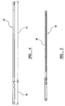
- the bar 12 shown in the figures is machined from a single piece of steel which is circular in cross section along the majority of its extent.
- the bar 12 includes a portion 14 that is arranged to be encased in carbon fibre 16.
- the portion 14 is of slightly less diameter than the exposed portion comprising the driving end 18 of the bar.
- the portion 14 includes grooves 20 each extending on opposed sides of the portion 14 towards the end of the portion 14 but not quite reaching that end.
- the bar is placed in a mould having the shape of the carbon fibre.
- a plug 22 is inserted through the end of the mould to contact a recess in the end of the portion 14.
- Plugs 24 are inserted through the sides of the mould into the groove 20. Plugs are inserted from each side of the mould in line with each other to firmly hold the bar in position in the mould.
- the plugs 24 can be located towards the end of the grooves 20 in order to prevent movement of the bar in its longitudinal direction as well as to support the bar in the mould. Alternatively, the plugs 24 can be spaced inwardly from the ends of the grooves.
- the plugs 22 can cooperate with the top and bottom surfaces of the groove and indeed are arranged to be a snug fit in those grooves, the bar is accurately held in the mould. In other embodiments, the plugs need not actually bear against the grooves and may be loosely located in the grooves.
- the carbon fibre is injected from beneath or from one or both ends or any combination thereof into the mould under considerable pressure to flow around the bar and around pins 26 that extend down into the mould and that contact the top of the portion 14 or are adjacent to that portion 14.
- the carbon fibre is caused to take up the shape shown.
- the portion 18 of the bar which is of a slightly larger diameter than the portion 14 abuts the end of the mould to restrict movement of the bar in a longitudinal direction that may tend to take the portion 18 into the mould.
- the portion 14 is approximately the same diameter as the end part 26 of the carbon fibre or slightly larger.
- the carbon fibre comprises a mixture of nylon resin including approximately 40% by volume of carbon fibres.
- the faller bar After moulding the carbon fibre around the pins and the portion 14, the faller bar is removed from the mould. An end 18 can then be bent into the position shown in Figure 2 to complete the faller bar to be ready for use for engagement with a driving mechanism. Alternately, the end 18 can be bent prior to moulding in which case the end can be held during moulding to prevent rotation of the bar about its longitudinal axis.
- the grooves 20 allow the major portion of the bar to comprise an I-beam. Accordingly, the bar is extremely strong and is able to resist any forces that may tend to cause the pins in the middle or at the end to move downwardly, when viewed in Figure 1, with respect to other pins. In addition, the carbon fibre locks firmly around the bar as it fills the grooves 20.
Landscapes
- Engineering & Computer Science (AREA)
- Mechanical Engineering (AREA)
- Textile Engineering (AREA)
- Insertion Pins And Rivets (AREA)
- Moulds For Moulding Plastics Or The Like (AREA)
Applications Claiming Priority (2)
| Application Number | Priority Date | Filing Date | Title |
|---|---|---|---|
| GBGB0025748.5A GB0025748D0 (en) | 2000-10-20 | 2000-10-20 | Faller bar |
| GB0025748 | 2000-10-20 |
Publications (1)
| Publication Number | Publication Date |
|---|---|
| EP1201801A1 true EP1201801A1 (de) | 2002-05-02 |
Family
ID=9901687
Family Applications (1)
| Application Number | Title | Priority Date | Filing Date |
|---|---|---|---|
| EP01308674A Withdrawn EP1201801A1 (de) | 2000-10-20 | 2001-10-11 | Nadelhalter mit Nadelstreifen |
Country Status (3)
| Country | Link |
|---|---|
| US (1) | US20020069504A1 (de) |
| EP (1) | EP1201801A1 (de) |
| GB (1) | GB0025748D0 (de) |
Families Citing this family (2)
| Publication number | Priority date | Publication date | Assignee | Title |
|---|---|---|---|---|
| US7159280B2 (en) * | 2003-10-20 | 2007-01-09 | Voshell Sr William E | Disposable faller bar with improved core |
| US20080022493A1 (en) * | 2006-07-27 | 2008-01-31 | Drei-S-Werk Prazisionswerkzeuge Gmbh & Co. Fertigungs-Kg | Needle bar for chain drawing frame |
Citations (3)
| Publication number | Priority date | Publication date | Assignee | Title |
|---|---|---|---|---|
| GB1117445A (en) * | 1964-07-01 | 1968-06-19 | Matthew Kenneth Mann | Improvements in or relating to faller bars and other comb-like members |
| IE36299B1 (en) * | 1972-04-17 | 1976-09-29 | Carbon Composites Ltd | Improved faller for a textile combing machine |
| GB2229459A (en) * | 1989-03-01 | 1990-09-26 | Bradford Steel Pin Manufacturi | Faller bars |
-
2000
- 2000-10-20 GB GBGB0025748.5A patent/GB0025748D0/en not_active Ceased
-
2001
- 2001-10-11 EP EP01308674A patent/EP1201801A1/de not_active Withdrawn
- 2001-10-15 US US09/977,744 patent/US20020069504A1/en not_active Abandoned
Patent Citations (3)
| Publication number | Priority date | Publication date | Assignee | Title |
|---|---|---|---|---|
| GB1117445A (en) * | 1964-07-01 | 1968-06-19 | Matthew Kenneth Mann | Improvements in or relating to faller bars and other comb-like members |
| IE36299B1 (en) * | 1972-04-17 | 1976-09-29 | Carbon Composites Ltd | Improved faller for a textile combing machine |
| GB2229459A (en) * | 1989-03-01 | 1990-09-26 | Bradford Steel Pin Manufacturi | Faller bars |
Also Published As
| Publication number | Publication date |
|---|---|
| GB0025748D0 (en) | 2000-12-06 |
| US20020069504A1 (en) | 2002-06-13 |
Similar Documents
| Publication | Publication Date | Title |
|---|---|---|
| AU2007200480B2 (en) | Clamping and articulation element | |
| EP2582894B1 (de) | Bewehrungsklemme zur verbindung von stäben unterschiedlicher grösse | |
| US6443723B1 (en) | Slide retainer for an injection mold | |
| CA2052697C (en) | Surgical stapler with locking means | |
| AU731589B2 (en) | Method of molding an optical connector ferrule | |
| CN1024583C (zh) | 由连接器相互接合在一起的异形杆材组成的可拆式支架 | |
| CN1912403B (zh) | 用于轴向锁定设有凹槽的销的装置 | |
| EP4177011B1 (de) | Axt und verfahren zur herstellung einer axt | |
| US6779312B2 (en) | Anchoring device | |
| EP1201801A1 (de) | Nadelhalter mit Nadelstreifen | |
| KR20100030607A (ko) | 평탄한 또는 평탄하지 않은 보어 가장자리를 디버링하기 위한 디버링 블레이드 | |
| JP4287883B2 (ja) | 編機バー | |
| CA2623781A1 (en) | Multi-position interlocking ink stick | |
| KR101020688B1 (ko) | 브러시 제조 방법 | |
| WO1998032578A1 (en) | Saw member, link of saw member and a method of producing a saw member | |
| NO145783B (no) | Slagverktoey. | |
| KR101373388B1 (ko) | 공구용기 | |
| US6601306B1 (en) | Tool and connection therefor between working portion and handle portion thereof | |
| KR100476496B1 (ko) | 시스템 부품 | |
| TWI327196B (en) | Link plate, chain link and energy guide chain, as well as intermediate piece for an energy guide chain, with torsion-coupled locking means to link the transverse link and the link plate | |
| US6874206B2 (en) | Component for regulating or modifying the effective length of a round steel chain | |
| JPH0952222A (ja) | Pc版製造用の端面型枠 | |
| CN102669893A (zh) | 带夹具 | |
| EP1136455A1 (de) | Element zum Schneiden von Glas und ähnlichem | |
| JP4045036B2 (ja) | 長尺物成形用中子 |
Legal Events
| Date | Code | Title | Description |
|---|---|---|---|
| PUAI | Public reference made under article 153(3) epc to a published international application that has entered the european phase |
Free format text: ORIGINAL CODE: 0009012 |
|
| AK | Designated contracting states |
Kind code of ref document: A1 Designated state(s): AT BE CH CY DE DK ES FI FR GB GR IE IT LI LU MC NL PT SE TR |
|
| AX | Request for extension of the european patent |
Free format text: AL;LT;LV;MK;RO;SI |
|
| 17P | Request for examination filed |
Effective date: 20021028 |
|
| AKX | Designation fees paid |
Free format text: AT BE CH CY DE DK ES FI FR GB GR IE IT LI LU MC NL PT SE TR |
|
| GRAP | Despatch of communication of intention to grant a patent |
Free format text: ORIGINAL CODE: EPIDOSNIGR1 |
|
| STAA | Information on the status of an ep patent application or granted ep patent |
Free format text: STATUS: THE APPLICATION IS DEEMED TO BE WITHDRAWN |
|
| 18D | Application deemed to be withdrawn |
Effective date: 20031212 |