EP1201837A2 - Zufuhrventil mit einem ausziehbaren Rohr für einen Spülkasten - Google Patents
Zufuhrventil mit einem ausziehbaren Rohr für einen Spülkasten Download PDFInfo
- Publication number
- EP1201837A2 EP1201837A2 EP01125277A EP01125277A EP1201837A2 EP 1201837 A2 EP1201837 A2 EP 1201837A2 EP 01125277 A EP01125277 A EP 01125277A EP 01125277 A EP01125277 A EP 01125277A EP 1201837 A2 EP1201837 A2 EP 1201837A2
- Authority
- EP
- European Patent Office
- Prior art keywords
- tubular member
- feed valve
- outlet pipe
- respect
- tank
- Prior art date
- Legal status (The legal status is an assumption and is not a legal conclusion. Google has not performed a legal analysis and makes no representation as to the accuracy of the status listed.)
- Withdrawn
Links
- XLYOFNOQVPJJNP-UHFFFAOYSA-N water Substances O XLYOFNOQVPJJNP-UHFFFAOYSA-N 0.000 claims abstract description 12
- 230000002093 peripheral effect Effects 0.000 claims abstract description 9
- 230000004075 alteration Effects 0.000 description 1
- 230000005484 gravity Effects 0.000 description 1
- 230000000284 resting effect Effects 0.000 description 1
Images
Classifications
-
- E—FIXED CONSTRUCTIONS
- E03—WATER SUPPLY; SEWERAGE
- E03D—WATER-CLOSETS OR URINALS WITH FLUSHING DEVICES; FLUSHING VALVES THEREFOR
- E03D1/00—Water flushing devices with cisterns ; Setting up a range of flushing devices or water-closets; Combinations of several flushing devices
- E03D1/30—Valves for high or low level cisterns; Their arrangement ; Flushing mechanisms in the cistern, optionally with provisions for a pre-or a post- flushing and for cutting off the flushing mechanism in case of leakage
- E03D1/32—Arrangement of inlet valves
Definitions
- the present invention relates to a feed valve with an extensible outlet pipe for a flush tank.
- a wide range of feed valves for flush tanks in general are known to comprise an inlet conduit connectable to the water mains; a valve assembly controlled by a float-activated lever; and an outlet pipe for feeding water into the tank.
- the free end of the outlet pipe must be located as close as possible to the bottom wall of the tank, so that, obviously, feed valves with outlet pipes of fixed length cannot be used on tanks of different depths.
- a feed valve with an extensible outlet pipe for a flush tank comprising an inlet conduit connectable to a water mains; a valve assembly controlled by a float; and an outlet pipe located downstream from said valve assembly; said outlet pipe comprising a first and a second tubular member connected telescopically, sliding axially with respect to each other along a predetermined axis, and communicating internally with each other; and the feed valve being characterized in that:
- the feed valve and, in particular, the outlet pipe with which it is provided are therefore much easier and cheaper to produce and assemble than known solutions; the length of the outlet pipe is adjusted quickly and easily, with no awkward maneuvering and, what is more, with no need for a fitter; the outlet pipe, in fact, is self-adjusting, in the sense that it adapts automatically to different tank depths, as described in detail below.
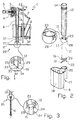
- a feed valve 1 for a flush tank 2 comprises a body 3 housing a valve assembly 4, e.g. a diaphragm type.
- Body 3 is connected to an inlet conduit 5, connectable to the water mains, and to an outlet pipe 6 located downstream from valve assembly 4 and substantially perpendicular to inlet conduit 5.
- inlet conduit 5 is substantially horizontal, and outlet pipe 6 substantially vertical.
- Valve assembly 4 is controlled by a control lever 7 connected mechanically to a float 8 fitted to an adjustable rod 9 fixed to body 3.
- Outlet pipe 6 comprises two tubular, substantially cylindrical members 11, 12, which are connected telescopically, slide axially with respect to each other along a common longitudinal axis 13, and communicate internally with each other.
- Tubular member 12 is fixed integrally to body 3 by a fastening end 14, and has a free end 15 opposite fastening end 14 and projecting outwards of body 3.
- Tubular member 11 is housed radially inside tubular member 12, slides axially with respect to tubular member 12 and body 3, and has open opposite axial ends 16, 17 communicating with tank 2 and with the inside of tubular member 12 respectively.
- Float 8 comprises a hollow, prismatic body 18 having, at an edge 19, a substantially cylindrical seat 20 through which tubular member 12 fits radially loosely. Float 8 slides freely with respect to tubular member 12.
- Tubular member 11 slides freely with respect to tubular member 12 when subjected to an axial load; and outlet pipe 6 has first and second stop means 21, 22 for limiting axial slide of tubular member 11 with respect to tubular member 12 in an extracted maximum-telescopic-extension position (shown in Figure 3) and a withdrawn minimum-telescopic-extension position (shown in Figure 1) respectively.
- first stop means 21 comprise respective radial portions 23, 24 of tubular members 11, 12, which project radially from tubular members 11, 12 to engage each other axially.
- tubular member 12 comprises a collar 24 projecting radially inwards from an end edge 25 of free end 15.
- Collar 24 defines a sliding seat 26 for tubular member 11, and cooperates in sliding manner, with a small amount of radial interference, with an outer lateral surface 27 of tubular member 11.
- a small amount of radial clearance may be provided between collar 24 and tubular member 11, so that, when outlet pipe 6 is positioned vertically, tubular member 11 slides with respect to tubular member 12 solely by virtue of its own weight.
- tubular member 11 is provided with teeth 23, which project radially outwards from outer lateral surface 27 to axially engage collar 24.
- teeth 23 In the example shown, two diametrically opposite pairs of teeth 23 are provided; and the teeth 23 in each pair are located side by side and separated by a slot 28 formed through the lateral wall of tubular member 11.
- Second stop means 22 comprise a radially outer collar 29 located at end 16 of tubular member 11 to axially engage end edge 25 of tubular member 12.
- End 16 of tubular member 11 has axial supporting means 31, which, in use, rest on a bottom wall 32 of tank 2 in a direction substantially parallel to axis 13; and radial-outflow means 33 enabling water to flow out of end 16 of tubular member 11 not only along axis 13 but also in a direction substantially perpendicular to axis 13, so that water can also flow out of tubular member 11 when end 16 rests on bottom wall 32.
- end 16 comprises an end opening 34 defined by a peripheral end edge 35 of tubular member 11; peripheral end edge 35 is oblique with respect to axis 13, and preferably slopes 45° with respect to axis 13 in longitudinal section; and outflow means 33 and supporting means 31 are defined by end opening 34 and peripheral end edge 35.
- tubular members 11, 12 may assume any intermediate position between the withdrawn minimum-telescopic-extension position - in which tubular member 11 is housed almost completely inside tubular member 12, and collar 29 rests against end edge 25 (Figure 1) - and the extracted maximum-telescopic-extension position - in which tubular member 11 extends almost entirely outside tubular member 12, and teeth 23 engage collar 24 axially to prevent withdrawal of tubular member 11 from tubular member 12 (Figure 3).
- Outlet pipe 6 may thus assume an overall length corresponding perfectly with the depth of tank 2, and feed valve 1 can be installed on flush tanks of different sizes with no major alterations required.
- tubular member 11 when outlet pipe 6 is positioned vertically, slides with respect to tubular member 12 solely by virtue of its own weight, so that the length of outlet pipe 6 is adjusted automatically when feed valve 1 is fixed to tank 2 in the correct operating position.
- Tubular member 12 in fact, remains connected integrally to body 3, while tubular member 11 drops by force of gravity and slides out of tubular member 12 until it comes to rest on bottom wall 32 of tank 2.
- outlet pipe 6 is adjusted according to the depth of tank 2 just as easily and quickly, even when tubular member 11 is connected to tubular member 12 with a certain amount of radial interference. That is, with tubular members 11, 12 set to the maximum-telescopic-extension position, peripheral end edge 35 is placed on bottom wall 32 of tank 2. If, in this condition, outlet pipe 6 is too long with respect to the depth of tank 2, tubular member 11, as feed valve 1 is set to the correct assembly position on tank 2, is pushed axially by bottom wall 32 inside tubular member 12, so that outlet pipe 6 automatically assumes the length required to keep peripheral end edge 35 resting on bottom wall 32.
Landscapes
- Health & Medical Sciences (AREA)
- Life Sciences & Earth Sciences (AREA)
- Engineering & Computer Science (AREA)
- Hydrology & Water Resources (AREA)
- Public Health (AREA)
- Water Supply & Treatment (AREA)
- Float Valves (AREA)
- Joints Allowing Movement (AREA)
- Cleaning In General (AREA)
- Domestic Plumbing Installations (AREA)
Applications Claiming Priority (2)
| Application Number | Priority Date | Filing Date | Title |
|---|---|---|---|
| ITMI000609U | 2000-10-25 | ||
| IT2000MI000609 IT250208Y1 (it) | 2000-10-25 | 2000-10-25 | Valvola di alimentazione con tubo di uscita estensibile per unacassetta di risciacquamento |
Publications (2)
| Publication Number | Publication Date |
|---|---|
| EP1201837A2 true EP1201837A2 (de) | 2002-05-02 |
| EP1201837A3 EP1201837A3 (de) | 2002-06-05 |
Family
ID=11444601
Family Applications (1)
| Application Number | Title | Priority Date | Filing Date |
|---|---|---|---|
| EP01125277A Withdrawn EP1201837A3 (de) | 2000-10-25 | 2001-10-24 | Zufuhrventil mit einem ausziehbaren Rohr für einen Spülkasten |
Country Status (2)
| Country | Link |
|---|---|
| EP (1) | EP1201837A3 (de) |
| IT (1) | IT250208Y1 (de) |
Citations (1)
| Publication number | Priority date | Publication date | Assignee | Title |
|---|---|---|---|---|
| US4108202A (en) | 1976-07-19 | 1978-08-22 | Adolf Schoepe | Ball cock having vertically adjustable outlet tube |
Family Cites Families (3)
| Publication number | Priority date | Publication date | Assignee | Title |
|---|---|---|---|---|
| US4938245A (en) * | 1989-09-25 | 1990-07-03 | Fluidmaster, Inc. | Low noise toilet tank valve |
| FR2724958B1 (fr) * | 1994-09-26 | 1996-12-27 | Ragot Claude | Installation de distribution d'eau pour reservoir de chasse de toilettes sanitaires |
| AUPP622398A0 (en) * | 1998-09-29 | 1998-10-22 | Beattie, David Dowley | Inlet valve for cisterns |
-
2000
- 2000-10-25 IT IT2000MI000609 patent/IT250208Y1/it active
-
2001
- 2001-10-24 EP EP01125277A patent/EP1201837A3/de not_active Withdrawn
Patent Citations (1)
| Publication number | Priority date | Publication date | Assignee | Title |
|---|---|---|---|---|
| US4108202A (en) | 1976-07-19 | 1978-08-22 | Adolf Schoepe | Ball cock having vertically adjustable outlet tube |
Also Published As
| Publication number | Publication date |
|---|---|
| EP1201837A3 (de) | 2002-06-05 |
| IT250208Y1 (it) | 2003-07-24 |
| ITMI20000609U1 (it) | 2002-04-25 |
Similar Documents
| Publication | Publication Date | Title |
|---|---|---|
| US8590069B2 (en) | Anti-overflow urinal and method | |
| US6484330B2 (en) | Combined faucet and drain assembly | |
| CN202992312U (zh) | 卫生龙头 | |
| US4589373A (en) | Watering device for fowl and small animals | |
| US5234018A (en) | Sewer check valve and cleanout apparatus | |
| US20040034926A1 (en) | Flexible bathtub waste pipe assembly for bathtubs and the like | |
| US4340082A (en) | Adjustable ballcock standpipe assembly | |
| GB2475297A (en) | Clogging resistant drain | |
| JP2002530769A (ja) | フローリミッタ | |
| GB2251919A (en) | Adjustable valve fitting assembly for tubs | |
| CA2520335A1 (en) | Flexible bathtub waste pipe assembly for bathtubs and the like | |
| US5031659A (en) | Sewer line relief valve | |
| DK1862604T3 (en) | filling valve | |
| CA2845558A1 (en) | Strainer with improved flow | |
| CN108603367B (zh) | 用于填充卫生水箱的阀门配件以及具有此种阀门配件的卫生水箱 | |
| CN102159773A (zh) | 用于装填马桶水箱的可调龙头 | |
| CN110878583B (zh) | 卫生间沉箱二次排水地漏预埋系统 | |
| US20060157109A1 (en) | Air gap apparatus for water dispenser | |
| KR101656623B1 (ko) | 높이조절이 가능한 슬리브 | |
| US7278178B2 (en) | Tub filler and overflow combination device | |
| EP0544261B1 (de) | Zwischenphase-Vakuumventil | |
| RU2306390C2 (ru) | Система крепления промывочного клапана | |
| CN118284763A (zh) | 阀 | |
| US3894301A (en) | Integrated drain and vent system for sinks | |
| KR200322595Y1 (ko) | 우오수받이의 유입/출구 위치조정장치 |
Legal Events
| Date | Code | Title | Description |
|---|---|---|---|
| PUAI | Public reference made under article 153(3) epc to a published international application that has entered the european phase |
Free format text: ORIGINAL CODE: 0009012 |
|
| PUAL | Search report despatched |
Free format text: ORIGINAL CODE: 0009013 |
|
| AK | Designated contracting states |
Kind code of ref document: A2 Designated state(s): AT BE CH CY DE DK ES FI FR GB GR IE IT LI LU MC NL PT SE TR |
|
| AX | Request for extension of the european patent |
Free format text: AL;LT;LV;MK;RO;SI |
|
| AK | Designated contracting states |
Kind code of ref document: A3 Designated state(s): AT BE CH CY DE DK ES FI FR GB GR IE IT LI LU MC NL PT SE TR |
|
| AX | Request for extension of the european patent |
Free format text: AL;LT;LV;MK;RO;SI |
|
| 17P | Request for examination filed |
Effective date: 20021205 |
|
| AKX | Designation fees paid |
Designated state(s): AT BE CH CY DE DK ES FI FR GB GR IE IT LI LU MC NL PT SE TR |
|
| 17Q | First examination report despatched |
Effective date: 20030228 |
|
| STAA | Information on the status of an ep patent application or granted ep patent |
Free format text: STATUS: THE APPLICATION IS DEEMED TO BE WITHDRAWN |
|
| 18D | Application deemed to be withdrawn |
Effective date: 20030911 |