EP1201904A2 - Contrôle de force motrice pour véhicule Diesel - Google Patents
Contrôle de force motrice pour véhicule Diesel Download PDFInfo
- Publication number
- EP1201904A2 EP1201904A2 EP01124130A EP01124130A EP1201904A2 EP 1201904 A2 EP1201904 A2 EP 1201904A2 EP 01124130 A EP01124130 A EP 01124130A EP 01124130 A EP01124130 A EP 01124130A EP 1201904 A2 EP1201904 A2 EP 1201904A2
- Authority
- EP
- European Patent Office
- Prior art keywords
- target
- engine
- drive force
- amount
- fresh air
- Prior art date
- Legal status (The legal status is an assumption and is not a legal conclusion. Google has not performed a legal analysis and makes no representation as to the accuracy of the status listed.)
- Granted
Links
- 238000012545 processing Methods 0.000 claims abstract description 16
- 239000000446 fuel Substances 0.000 claims description 81
- 238000002347 injection Methods 0.000 claims description 78
- 239000007924 injection Substances 0.000 claims description 78
- 230000005540 biological transmission Effects 0.000 claims description 14
- 238000010586 diagram Methods 0.000 description 19
- 238000001514 detection method Methods 0.000 description 18
- 230000004044 response Effects 0.000 description 18
- 239000007789 gas Substances 0.000 description 9
- 238000010276 construction Methods 0.000 description 7
- 230000009467 reduction Effects 0.000 description 7
- 230000001133 acceleration Effects 0.000 description 5
- 230000000694 effects Effects 0.000 description 2
- 230000001771 impaired effect Effects 0.000 description 2
- 238000005070 sampling Methods 0.000 description 2
- 239000000779 smoke Substances 0.000 description 2
- 238000012546 transfer Methods 0.000 description 2
- QVGXLLKOCUKJST-UHFFFAOYSA-N atomic oxygen Chemical compound [O] QVGXLLKOCUKJST-UHFFFAOYSA-N 0.000 description 1
- 238000002485 combustion reaction Methods 0.000 description 1
- 230000006835 compression Effects 0.000 description 1
- 238000007906 compression Methods 0.000 description 1
- 238000012937 correction Methods 0.000 description 1
- 230000007423 decrease Effects 0.000 description 1
- 238000002474 experimental method Methods 0.000 description 1
- 230000006872 improvement Effects 0.000 description 1
- 238000000034 method Methods 0.000 description 1
- 238000012986 modification Methods 0.000 description 1
- 230000004048 modification Effects 0.000 description 1
- 239000001301 oxygen Substances 0.000 description 1
- 229910052760 oxygen Inorganic materials 0.000 description 1
- 230000035945 sensitivity Effects 0.000 description 1
- 238000011144 upstream manufacturing Methods 0.000 description 1
Images


Classifications
-
- F—MECHANICAL ENGINEERING; LIGHTING; HEATING; WEAPONS; BLASTING
- F02—COMBUSTION ENGINES; HOT-GAS OR COMBUSTION-PRODUCT ENGINE PLANTS
- F02D—CONTROLLING COMBUSTION ENGINES
- F02D41/00—Electrical control of supply of combustible mixture or its constituents
- F02D41/0025—Controlling engines characterised by use of non-liquid fuels, pluralities of fuels, or non-fuel substances added to the combustible mixtures
- F02D41/0047—Controlling exhaust gas recirculation [EGR]
- F02D41/005—Controlling exhaust gas recirculation [EGR] according to engine operating conditions
-
- F—MECHANICAL ENGINEERING; LIGHTING; HEATING; WEAPONS; BLASTING
- F02—COMBUSTION ENGINES; HOT-GAS OR COMBUSTION-PRODUCT ENGINE PLANTS
- F02D—CONTROLLING COMBUSTION ENGINES
- F02D23/00—Controlling engines characterised by their being supercharged
- F02D23/02—Controlling engines characterised by their being supercharged the engines being of fuel-injection type
-
- F—MECHANICAL ENGINEERING; LIGHTING; HEATING; WEAPONS; BLASTING
- F02—COMBUSTION ENGINES; HOT-GAS OR COMBUSTION-PRODUCT ENGINE PLANTS
- F02D—CONTROLLING COMBUSTION ENGINES
- F02D41/00—Electrical control of supply of combustible mixture or its constituents
- F02D41/02—Circuit arrangements for generating control signals
- F02D41/021—Introducing corrections for particular conditions exterior to the engine
- F02D41/0215—Introducing corrections for particular conditions exterior to the engine in relation with elements of the transmission
- F02D41/0225—Introducing corrections for particular conditions exterior to the engine in relation with elements of the transmission in relation with the gear ratio or shift lever position
-
- B—PERFORMING OPERATIONS; TRANSPORTING
- B60—VEHICLES IN GENERAL
- B60W—CONJOINT CONTROL OF VEHICLE SUB-UNITS OF DIFFERENT TYPE OR DIFFERENT FUNCTION; CONTROL SYSTEMS SPECIALLY ADAPTED FOR HYBRID VEHICLES; ROAD VEHICLE DRIVE CONTROL SYSTEMS FOR PURPOSES NOT RELATED TO THE CONTROL OF A PARTICULAR SUB-UNIT
- B60W2510/00—Input parameters relating to a particular sub-units
- B60W2510/10—Change speed gearings
- B60W2510/1005—Transmission ratio engaged
-
- B—PERFORMING OPERATIONS; TRANSPORTING
- B60—VEHICLES IN GENERAL
- B60W—CONJOINT CONTROL OF VEHICLE SUB-UNITS OF DIFFERENT TYPE OR DIFFERENT FUNCTION; CONTROL SYSTEMS SPECIALLY ADAPTED FOR HYBRID VEHICLES; ROAD VEHICLE DRIVE CONTROL SYSTEMS FOR PURPOSES NOT RELATED TO THE CONTROL OF A PARTICULAR SUB-UNIT
- B60W2710/00—Output or target parameters relating to a particular sub-units
- B60W2710/06—Combustion engines, Gas turbines
- B60W2710/0666—Engine torque
-
- B—PERFORMING OPERATIONS; TRANSPORTING
- B60—VEHICLES IN GENERAL
- B60W—CONJOINT CONTROL OF VEHICLE SUB-UNITS OF DIFFERENT TYPE OR DIFFERENT FUNCTION; CONTROL SYSTEMS SPECIALLY ADAPTED FOR HYBRID VEHICLES; ROAD VEHICLE DRIVE CONTROL SYSTEMS FOR PURPOSES NOT RELATED TO THE CONTROL OF A PARTICULAR SUB-UNIT
- B60W2710/00—Output or target parameters relating to a particular sub-units
- B60W2710/10—Change speed gearings
- B60W2710/105—Output torque
-
- F—MECHANICAL ENGINEERING; LIGHTING; HEATING; WEAPONS; BLASTING
- F02—COMBUSTION ENGINES; HOT-GAS OR COMBUSTION-PRODUCT ENGINE PLANTS
- F02B—INTERNAL-COMBUSTION PISTON ENGINES; COMBUSTION ENGINES IN GENERAL
- F02B3/00—Engines characterised by air compression and subsequent fuel addition
- F02B3/06—Engines characterised by air compression and subsequent fuel addition with compression ignition
-
- F—MECHANICAL ENGINEERING; LIGHTING; HEATING; WEAPONS; BLASTING
- F02—COMBUSTION ENGINES; HOT-GAS OR COMBUSTION-PRODUCT ENGINE PLANTS
- F02D—CONTROLLING COMBUSTION ENGINES
- F02D2250/00—Engine control related to specific problems or objectives
- F02D2250/18—Control of the engine output torque
-
- F—MECHANICAL ENGINEERING; LIGHTING; HEATING; WEAPONS; BLASTING
- F02—COMBUSTION ENGINES; HOT-GAS OR COMBUSTION-PRODUCT ENGINE PLANTS
- F02D—CONTROLLING COMBUSTION ENGINES
- F02D41/00—Electrical control of supply of combustible mixture or its constituents
- F02D41/02—Circuit arrangements for generating control signals
- F02D41/18—Circuit arrangements for generating control signals by measuring intake air flow
- F02D41/187—Circuit arrangements for generating control signals by measuring intake air flow using a hot wire flow sensor
-
- F—MECHANICAL ENGINEERING; LIGHTING; HEATING; WEAPONS; BLASTING
- F02—COMBUSTION ENGINES; HOT-GAS OR COMBUSTION-PRODUCT ENGINE PLANTS
- F02M—SUPPLYING COMBUSTION ENGINES IN GENERAL WITH COMBUSTIBLE MIXTURES OR CONSTITUENTS THEREOF
- F02M26/00—Engine-pertinent apparatus for adding exhaust gases to combustion-air, main fuel or fuel-air mixture, e.g. by exhaust gas recirculation [EGR] systems
- F02M26/02—EGR systems specially adapted for supercharged engines
- F02M26/04—EGR systems specially adapted for supercharged engines with a single turbocharger
- F02M26/05—High pressure loops, i.e. wherein recirculated exhaust gas is taken out from the exhaust system upstream of the turbine and reintroduced into the intake system downstream of the compressor
-
- F—MECHANICAL ENGINEERING; LIGHTING; HEATING; WEAPONS; BLASTING
- F16—ENGINEERING ELEMENTS AND UNITS; GENERAL MEASURES FOR PRODUCING AND MAINTAINING EFFECTIVE FUNCTIONING OF MACHINES OR INSTALLATIONS; THERMAL INSULATION IN GENERAL
- F16H—GEARING
- F16H63/00—Control outputs from the control unit to change-speed- or reversing-gearings for conveying rotary motion or to other devices than the final output mechanism
- F16H63/40—Control outputs from the control unit to change-speed- or reversing-gearings for conveying rotary motion or to other devices than the final output mechanism comprising signals other than signals for actuating the final output mechanisms
- F16H63/50—Signals to an engine or motor
-
- Y—GENERAL TAGGING OF NEW TECHNOLOGICAL DEVELOPMENTS; GENERAL TAGGING OF CROSS-SECTIONAL TECHNOLOGIES SPANNING OVER SEVERAL SECTIONS OF THE IPC; TECHNICAL SUBJECTS COVERED BY FORMER USPC CROSS-REFERENCE ART COLLECTIONS [XRACs] AND DIGESTS
- Y02—TECHNOLOGIES OR APPLICATIONS FOR MITIGATION OR ADAPTATION AGAINST CLIMATE CHANGE
- Y02T—CLIMATE CHANGE MITIGATION TECHNOLOGIES RELATED TO TRANSPORTATION
- Y02T10/00—Road transport of goods or passengers
- Y02T10/10—Internal combustion engine [ICE] based vehicles
- Y02T10/12—Improving ICE efficiencies
-
- Y—GENERAL TAGGING OF NEW TECHNOLOGICAL DEVELOPMENTS; GENERAL TAGGING OF CROSS-SECTIONAL TECHNOLOGIES SPANNING OVER SEVERAL SECTIONS OF THE IPC; TECHNICAL SUBJECTS COVERED BY FORMER USPC CROSS-REFERENCE ART COLLECTIONS [XRACs] AND DIGESTS
- Y02—TECHNOLOGIES OR APPLICATIONS FOR MITIGATION OR ADAPTATION AGAINST CLIMATE CHANGE
- Y02T—CLIMATE CHANGE MITIGATION TECHNOLOGIES RELATED TO TRANSPORTATION
- Y02T10/00—Road transport of goods or passengers
- Y02T10/10—Internal combustion engine [ICE] based vehicles
- Y02T10/40—Engine management systems
Definitions
- This invention relates to a drive force controller for a vehicle equipped with a diesel engine.
- a target engine torque may be a large value transitionally exceeding a realizable upper limit level. It is then not only impossible to realize the target drive force, but it may be determined that drive force is a characteristic of the maximum engine torque characteristic unrelated to drivability, and drivability may be impaired.
- a first target drive force is set from the accelerator pedal control input as the drive force required by the driver. Dynamic delay processing is applied to this first target drive force as a first order lag so as to set a second target drive force.
- the target drive force may be expressed as a relation of the following equation (1) from the engine torque and speed ratio.
- the engine torque required to realize the aforesaid second target drive force is calculated, and the fuel injection amount of the diesel engine is controlled to this engine torque.
- Fd (Te ⁇ G ⁇ G ⁇ )/Rtire where, in Eqn. (1)
- a feature of the engine torque response of a diesel engine is that when an excess air rate is to some extent large, the response is effectively without delay according to the fuel injection amount, but the sensitivity to the fuel injection amount becomes smaller and is strongly governed by the response to the fresh air intake amount as the excess air rate becomes small.
- the excess air rate should be as large as possible so that there is not much effect due to the fresh air intake amount which has a slow response, but considering the exhaust performance, there is a need to reduce the fresh air intake amount at low or medium engine load, to increase exhaust gas recirculation (EGR), to suppress NOx.
- EGR exhaust gas recirculation
- the target value of the fresh air intake amount is usually set according to the engine load, and the fresh air intake amount is therefore determined according to the target fuel injection amount.
- the target fuel injection amount is set after performing delay processing on the target drive force.
- the target fresh air intake amount is affected by delay processing, which conflicts with the requirement that the fresh air intake amount should be increased as rapidly as possible.
- the invention provides a drive force controller for a vehicle provided with a diesel engine and a transmission, the transmission changes an output rotation of the engine.
- the controller comprises a sensor which detects an accelerator pedal operation amount of the engine, a sensor which detects a fresh air amount drawn in by the engine, a sensor which detects an engine rotation speed, a sensor which detects a speed ratio of the transmission, and a controller functioning to calculate a first target drive force based on the operation amount of the accelerator pedal, apply dynamic delay processing to the first target drive force to calculate a second target drive force, calculate a target engine fresh air intake amount from the first target drive force, the speed ratio and the engine rotation speed, control the fresh air intake amount of the engine to this target fresh air intake amount, control a torque of the engine based on the second target drive force, the speed ratio, the fresh air intake amount and the engine rotation speed.
- Fig. 1 is a system diagram of a vehicle according to a first embodiment of this invention.
- Fig. 2 is a block diagram of drive force control in this system.
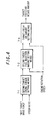
- Fig. 3 is a block diagram of an engine torque control means.
- Fig. 4 is a block diagram of a target intake fresh air amount setting means.
- Fig. 5 is a map which sets a first target drive force.
- Fig. 6 is a map which sets a first target fuel injection amount.
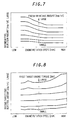
- Fig. 7 is a map which sets a maximum fuel injection amount.
- Fig. 8 is a map which sets a second target fuel injection amount.
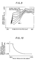
- Fig. 9 is a map which sets a target fresh air intake amount.
- Fig. 10 is a diagram showing a table which sets an EGR valve opening.
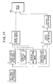
- Fig. 11 is a drive force control block diagram showing a second embodiment of this invention.
- Fig. 12 is a block diagram of a means which sets a target EGR rate.
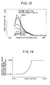
- Fig. 13 is a map which sets the target EGR rate.
- Fig. 14 is a diagram showing a table which sets the EGR valve opening.
- Fig. 15 is a system diagram of a vehicle according to a third embodiment of this invention.
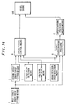
- Fig. 16 is a drive force control block diagram in this system.
- Fig. 17 is a block diagram of a means which sets a target supercharging pressure.
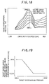
- Fig. 18 is a map which sets the target supercharging pressure.
- Fig. 19 is a diagram showing a table which sets the supercharger nozzle opening.
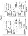
- Fig. 20 is a diagram describing the effectiveness of this invention.
- Fig. 1 schematically shows the construction of the vehicle.
- a diesel engine 100 mounted to a vehicle draws in fresh air (air) into a cylinder via an intake passage 101, and fuel is injected into the cylinder from an injector 102.
- the fuel is burnt by compression ignition, and the exhaust gas after combustion is discharged from an exhaust passage 103.
- EGR exhaust gas recirculation
- An EGR valve 105 is interposed in the EGR passage 104, and the exhaust gas recirculation rate is controlled by controlling the opening of this EGR valve 105. This also results in the control of the fresh air amount drawn in into the cylinder.
- a continuously variable transmission (hereafter referred to as CVT) 107 is provided on the output side of this engine 100, and the output of the CVT107 is transmitted to a drive wheel 109 via a final reduction gear 108.
- CVT continuously variable transmission
- a controller 200 for drive force control is provided to control the CVT107 and the engine 100.
- This drive force control realizes a target drive force computed based on a running condition such as accelerator pedal operating amount, by controlling the engine torque and CVT speed ratio.
- the controller 200 controls the fuel injection amount injected from the aforesaid injector 102, and the opening of the EGR valve 105.
- signals are input to the controller 200 from an accelerator pedal sensor 201 which detects the operating amount of the accelerator pedal, an air flow sensor 202 which detects the fresh air intake amount on the intake side of the intake passage 101, an engine rotation sensor 203 which detects the rotation speed of the engine 100, and a vehicle speed sensor 204 which detects the vehicle speed (output rotation speed of the CVT 107).
- the drive force controller comprising the controller 200 for drive force control is shown in the block diagram of Fig. 2.
- the drive force controller comprises a first target drive force setting means 1, a second target drive force setting means 2, a speed ratio detection means 3, a fresh air intake amount detection means 4, an engine rotation speed detection means 5, an engine torque control means 6, a target fresh air intake amount setting means 7, and a fresh air intake amount control means 8.
- the detailed construction of the engine torque control means 6 is shown in Fig. 3, and the detailed construction of the target fresh air intake amount setting means 7 is shown in Fig. 4.
- the target drive force setting means 1 sets a first target drive force tFd1 as a target value of the force exerted by the drive wheels on the road surface, for example from the accelerator pedal operating amount deg and vehicle speed Km/h.
- the relation between the accelerator pedal operating amount, vehicle speed and first target drive force is prepared beforehand as a map.
- An example of the map which sets the first target drive force is shown in Fig. 5.
- the second target drive force setting means 2 sets a second target drive force tFd2 by performing dynamic delay processing from the first target drive force tFd1 .
- the second target drive force is calculated from the first target drive force, for example based on the following equation (2).
- This equation (2) uses the transfer function of a continuous time system. S is the Laplacian operator.
- tFd2 [1/(1+ ⁇ aS)] ⁇ tFd1
- the actual computation is performed by computing the second target drive force by, for example, the following equation (3), by performing a discrete time computation.
- Z is the Z operator.
- tFd2 ⁇ ( ⁇ t/2 ⁇ a) ⁇ [tFd1+z -1 tFd1]+ (1- ⁇ t/2 ⁇ a) ⁇ z -1 tFd2 ⁇ ⁇ ( ⁇ t/2 ⁇ a+1) -1
- ⁇ a is given as a constant, it may be changed according to the running state.
- ⁇ t is given as a constant.
- the aforesaid speed ratio detection means 3 detects the speed ratio of the CVT107. Specifically, the speed ratio is calculated as [input rotation speed/output rotation speed] of the CVT107 from the engine rotation speed and the vehicle speed.
- rotation sensors for the input and output of the CVT107 may be used.
- the fresh air intake amount detection means 4 detects the fresh air amount drawn in by each cylinder.
- the fresh air amount drawn in by an intake air collector may for example be detected by an air flow sensor 202, and the amount drawn in by each cylinder estimated considering the dynamic characteristics of the intake air flow in the intake air collector.
- the fresh air amount Qw drawn in by the intake air collector and the fresh air amount Qcw drawn in by the cylinder are approximately expressed by the following equation (4) as a transfer function of a continuous time system.
- Qcw [1/(1+2aS)] ⁇ Qw
- ⁇ t is given as a constant.
- the engine speed detection means 5 detects the engine rotation speed by the engine rotation sensor 203.
- the engine torque control means 6 controls the engine torque based on the second target drive force tFd2 , the aforesaid speed ratio, the aforesaid fresh air intake amount and the aforesaid engine rotation speed.
- the engine torque control means 6, as shown in Fig.6, comprises a first target engine torque setting means 6-1, first target fuel injection amount setting means 6-2, maximum fuel injection amount setting means 6-3, command fuel injection amount setting means 6-4, and fuel injection amount control means 6-5.
- the aforesaid target engine torque setting means 6-1 first calculates the first target engine torque tTe1 as the engine torque required to realize the second target drive force tFd2 from the second target drive force and the speed ratio, for example from the following equation (6).
- This equation is deduced from equation (1) which calculates the drive force from the engine torque and speed ratio.
- tTe1 (tFd2 ⁇ Rtire)/(G ⁇ Gf) where, in equation (6),
- the first target fuel injection amount setting means 6-2 sets the first target fuel injection amount tQf1 from the first target engine torque tTe1 and engine rotation speed.
- the relation between the first target engine torque, engine rotation speed and the first target fuel injection amount is prepared beforehand as a map.
- An example of the map which sets the first target fuel injection amount is shown in Fig. 6. This map is found by experiment etc. as a characteristic of the engine torque relative to the engine rotation speed and fuel injection amount.
- the maximum fuel injection amount setting means 6-3 sets a maximum fuel injection amount Qf-max as a ceiling value of the fuel injection amount from the fresh air intake amount and engine rotation speed based on a limit on the rich side of the excess air rate.
- the relation between the fresh air intake amount, engine rotation speed and maximum fuel injection amount is prepared beforehand as a map.
- An example of the map which sets the maximum fuel injection amount is shown in Fig. 7. This map may be found from the excess air rate corresponding to a smoke generation amount tolerance level relative to the engine rotation speed.
- numerical values of the map lattice axes are substituted for the fresh air intake amount and engine rotation speed on the right-hand side of equation (7) shown below, and the maximum fuel injection amount equivalent to this lattice is calculated.
- Qf-max Qcw/( ⁇ min (Ne) ⁇ k) where, in equation (7),
- k is given as a constant corresponding to the stoichiometric air-fuel ratio when the oxygen in the EGR gas is ignored, and when it is not ignored, it is set as a function of the target EGR rate.
- the command fuel injection amount setting means 6-4 sets the command fuel injection amount iQf using the following equation (8) from the first target fuel injection amount tQf1 and maximum fuel injection amount Qf-max.
- the first target fuel injection amount is limited by the maximum fuel injection amount, and the command fuel injection amount is set.
- the fuel injection amount control means 6-5 controls the energization time of the injector 102 so that the actual fuel injection amount follows the command fuel injection amount.
- the target fresh air intake amount setting means 7 of Fig. 2 sets a target intake fresh air amount by an algebraic computation which does not include dynamic delay processing, from the first target drive force, the speed ratio and the engine rotation speed.
- the target fresh air intake amount setting means 7 comprises the second target engine torque setting means 7-1, second target fuel injection amount setting means 7-2 and the target fresh air intake amount setting means 7-3, as shown in Fig. 4.
- the second target engine torque setting means 7-1 calculates the following equation (9) for the second target engine torque tTe2 as an engine torque required to realize first target drive force tFd1 .
- the second target fuel injection amount setting means 7-2 sets the second target fuel injection amount tQf2 from the second target engine torque and engine rotation speed.
- the relation between the second target engine torque, engine rotation speed and second target fuel injection amount is prepared beforehand as a map.
- An example of the map which sets the second target fuel injection amount is shown in Fig. 8, and the map settings are identical values to those of Fig. 6.
- the second target fuel injection amount is not a target value of the actual fuel injection amount, but is calculated as a parameter for setting the target fresh air intake amount.
- the target fresh air intake amount setting means 7-3 sets a target intake fresh air amount from the second target fuel injection amount and engine rotation speed.
- the relation between the second target fuel injection amount, engine rotation speed and target fresh air intake amount is prepared beforehand as a map.
- An example of the map which sets the target fresh air intake amount is shown in Fig. 9.
- the target fresh air intake amount may be set from the second target engine torque and engine rotation speed. In this case, the second target fuel injection amount setting means 7-2 is unnecessary.
- the intake fresh air amount control means 8 controls the opening of the EGR valve 105 so that the actual fresh air intake follows the target intake fresh air amount.
- the characteristics of the EGR valve opening relative to the target fresh air amount are shown in Fig. 10. If the opening of the EGR valve 105 is made small, the exhaust gas recirculation amount will become less, and the fresh air intake amount will increase.
- dynamic delay processing is performed on the first target drive force to set the second target drive force.
- the engine torque no longer exceeds an upper limit level even during acceleration, it is necessary to make the fresh air intake amount increase promptly within the limits of the upper limit level of engine torque during such an acceleration. This is because the response of the engine torque to the increase in fuel injection amount increases, the larger the excess air rate.
- the target fresh air intake amount is set based on the first target drive force and the speed ratio of the CVT107, and does not contain dynamic delay processing here. Therefore, the response of the increase in the fresh air intake amount is accelerated, and the engine torque required for acceleration promptly increases.
- the fresh air intake amount can also be increased by making the opening of the EGR valve 105 small.
- Fig. 11 is a block diagram of the drive force controller in the case of the second embodiment.
- This drive force controller comprises a first target drive force setting means 1, second target drive force setting means 2, speed ratio detection means 3, fresh air intake amount detection means 4, engine speed detection means 5, engine torque control means 6, target EGR rate setting means 9, and EGR rate control means 10.
- the detailed construction of the target EGR rate setting means 9 is shown in Fig. 12.
- the first target drive force setting means 1, second target drive force setting means 2, speed ratio detection means 3, fresh air intake amount detection means 4, engine speed detection means 5 and engine torque control means 6 are identical to what was described in the first embodiment shown in Fig. 2 and Fig. 3.
- the difference from the first embodiment is that the target intake fresh air amount setting means 7 and the fresh air intake amount control means 8 are replaced by the target EGR rate setting means 9 and the EGR rate control means 10.
- a target EGR rate is set instead of the target fresh air intake amount, and the intake fresh air intake amount is controlled indirectly.
- the purpose of the invention is the same as that of the first embodiment, i.e., to enhance the response of the fresh air intake amount relative to an accelerator pedal operation, and thereby improve engine torque controllability and drivability.
- the target EGR rate setting means 9 sets the target EGR rate by an algebraic operation which does not involve dynamic delay processing from first target drive force, the speed ratio and the engine rotation speed.
- the target EGR rate setting means 9 comprises a second target engine torque setting means 7-1, second target fuel injection amount setting means 7-2 and target intake fresh air amount setting means 9-3, as shown in Fig. 12.
- the second target engine torque setting means 7-1 and the second target fuel injection amount setting means 7-2 are identical to what was described in Fig. 4.
- FIG. 4 A different point from Fig. 4 is that the target intake fresh air amount setting means 7-3 is replaced by a target EGR rate setting means 9-3.
- the target EGR rate setting means 9-3 sets the target EGR rate from the second target fuel injection amount and engine rotation speed.
- the relation between the second target fuel injection amount, engine rotation speed and target EGR rate is prepared beforehand as a map.
- An example of a map which sets this target EGR rate is shown in Fig. 13.
- the target EGR rate can also be set from the second target engine torque and engine rotation speed. In this case, the second target fuel injection amount setting means 7-2 becomes unnecessary.
- the EGR rate control means 10 controls the opening of the EGR valve 105 so that the actual EGR rate follows the target EGR rate.
- the characteristics of the EGR valve opening relative to the target EGR rate are shown in Fig. 14.
- the intake air amount can be controlled with sufficient response by controlling the EGR rate to the target EGR rate.
- the fuel injection amount can be increased with sufficient response during acceleration.
- Fig. 15 is a system diagram of the vehicle in the case of the third embodiment.
- a supercharger 106 is provided in the engine 100 wherein a compressor on the intake air side is rotated by an exhaust gas turbine.
- This supercharger 106 is a variable capacity type, the supercharging pressure being controlled by varying the opening of a nozzle as a component of a throttle on the upstream side of the turbine.
- the intake air amount is controlled by changing this supercharging pressure.
- the drive force controller 200 performs fuel injection control on the injector 102, and supercharging pressure control (nozzle opening control) on the supercharger 106 for drive force control.
- Fig. 16 is a block diagram of the drive force controller.
- the drive force controller comprises the first target drive force setting means 1, second target drive force setting means 2, speed ratio detection means 3, fresh air intake amount detection means 4, engine speed detection means 5, engine torque control means 6, target supercharging pressure setting means 11 and supercharging pressure control means 12.
- first target drive force setting means 1 the first target drive force setting means 1, second target drive force setting means 2, speed ratio detection means 3, fresh air intake amount detection means 4, engine speed detection means 5 and engine torque control means 6 are identical to what was described in Fig. 2 and Fig. 3.
- the target intake fresh air amount setting means 7 and intake fresh air amount operation means 8 are replaced by a target supercharging pressure setting means 11 and a supercharging pressure control means 12.
- this third embodiment controls the intake fresh air amount indirectly by setting not the target fresh air intake amount but the target supercharging pressure, and controlling the supercharging pressure. In this case also, engine torque controllability and drivability are improved by accelerating the response of the fresh air intake amount to accelerator pedal operation.
- the target supercharging pressure setting means 11 and the supercharging pressure control means 12 will now be mainly described.
- the target supercharging pressure setting means 11 sets the target supercharging pressure by an algebraic operation which does not contain dynamic delay processing from the first target drive force, the speed ratio and the engine rotation speed.
- the target supercharging pressure setting means 11 comprises the second target engine torque setting means 7-1, second target fuel injection amount setting means 7-2 and target supercharging pressure setting means 11-3, as shown in Fig. 17.
- the second target engine torque setting means 7-1 and second target fuel injection amount setting means 7-2 are identical to what was described in Fig. 4.
- the difference from the first embodiment is that the target intake fresh air amount setting means 7-3 is replaced by the target supercharging pressure setting means 11-3.
- the target supercharging pressure setting means 11-3 sets the target supercharging pressure from the second target fuel injection amount and engine rotation speed.
- the relation between the second target fuel injection amount, engine rotation speed and target supercharging pressure is prepared beforehand as a map.
- An example of a map which sets the target supercharging pressure is shown in Fig. 18.
- the target supercharging pressure can also be set from the second target engine torque and engine rotation speed.
- the second target fuel injection amount setting means 7-2 is unnecessary.
- the supercharging pressure control means 12 controls the nozzle opening of the supercharger 106 so that the actual supercharging pressure follows the target supercharging pressure.
- the opening of the EGR valve 105 may be controlled so that the actual supercharging pressure follows the target supercharging pressure.
- the system construction in this case is identical to that of Fig. 1.
- FIG. 20 The effectiveness of this invention is shown in Fig. 20 by comparison with the prior art. This diagram shows the characteristics of the first embodiment, but an identical effect is obtained with the second and third embodiment.
- the target fresh air intake amount can be made to increase rapidly simultaneously with the accelerator pedal depression, and the response of the fresh air intake amount to an accelerator pedal operation is enhanced. Due to the faster response of the fresh air intake amount, the appearance of the upper limiting level of engine torque determined by the maximum fuel injection amount can be made more rapid. Consequently, compared with the prior art, the restriction on the target engine torque (equivalent to the first target engine torque in this invention) decreases, and the ability to follow the target value of drive force improves as shown by the second target engine torque.
Landscapes
- Engineering & Computer Science (AREA)
- Chemical & Material Sciences (AREA)
- Combustion & Propulsion (AREA)
- Mechanical Engineering (AREA)
- General Engineering & Computer Science (AREA)
- Electrical Control Of Air Or Fuel Supplied To Internal-Combustion Engine (AREA)
- Combined Controls Of Internal Combustion Engines (AREA)
- Supercharger (AREA)
- Exhaust-Gas Circulating Devices (AREA)
- Output Control And Ontrol Of Special Type Engine (AREA)
- Control Of Vehicle Engines Or Engines For Specific Uses (AREA)
Applications Claiming Priority (2)
| Application Number | Priority Date | Filing Date | Title |
|---|---|---|---|
| JP2000331185 | 2000-10-30 | ||
| JP2000331185A JP2002138872A (ja) | 2000-10-30 | 2000-10-30 | ディーゼルエンジン搭載車両の駆動力制御装置 |
Publications (3)
| Publication Number | Publication Date |
|---|---|
| EP1201904A2 true EP1201904A2 (fr) | 2002-05-02 |
| EP1201904A3 EP1201904A3 (fr) | 2003-07-30 |
| EP1201904B1 EP1201904B1 (fr) | 2005-12-28 |
Family
ID=18807569
Family Applications (1)
| Application Number | Title | Priority Date | Filing Date |
|---|---|---|---|
| EP01124130A Expired - Lifetime EP1201904B1 (fr) | 2000-10-30 | 2001-10-10 | Contrôle de force motrice pour véhicule Diesel |
Country Status (3)
| Country | Link |
|---|---|
| EP (1) | EP1201904B1 (fr) |
| JP (1) | JP2002138872A (fr) |
| DE (1) | DE60116231T2 (fr) |
Cited By (3)
| Publication number | Priority date | Publication date | Assignee | Title |
|---|---|---|---|---|
| WO2004058534A1 (fr) * | 2002-12-30 | 2004-07-15 | Volvo Lastvagnar Ab | Procede de regulation d'egr (recirculation de gaz d'echappement) dans un moteur a combustion interne et vehicule a moteur comprenant des moyens electroniques permettant de mettre en oeuvre ce procede |
| US9869259B1 (en) * | 2016-10-05 | 2018-01-16 | GM Global Technology Operations LLC | System and method for vehicle propulsion system control |
| CN108999709A (zh) * | 2017-06-07 | 2018-12-14 | 罗伯特·博世有限公司 | 用于计算内燃机的充气量的方法 |
Families Citing this family (1)
| Publication number | Priority date | Publication date | Assignee | Title |
|---|---|---|---|---|
| JP5549457B2 (ja) * | 2010-07-22 | 2014-07-16 | トヨタ自動車株式会社 | 内燃機関の制御装置 |
Citations (2)
| Publication number | Priority date | Publication date | Assignee | Title |
|---|---|---|---|---|
| JPH11326959A (ja) | 1998-05-19 | 1999-11-26 | Seiko Epson Corp | アクティブマトリクス基板およびその製造方法ならびにアクティブマトリクス基板を有する液晶パネルおよび電子機器 |
| JP2000331185A (ja) | 1999-05-24 | 2000-11-30 | Sony Corp | 画像処理方法、画像処理装置、及びプログラム提供媒体 |
Family Cites Families (6)
| Publication number | Priority date | Publication date | Assignee | Title |
|---|---|---|---|---|
| KR960000634B1 (ko) * | 1991-06-26 | 1996-01-10 | 마쯔다 가부시기가이샤 | 자동변속기를 장착한 엔진의 제어장치 |
| EP0879731B1 (fr) * | 1997-05-22 | 2002-07-24 | Nissan Motor Company, Limited | Dispositif de commande pour moteur et transmission à variation continue automatique à commande électronique |
| EP0925992B1 (fr) * | 1997-12-19 | 2006-03-15 | Nissan Motor Co., Ltd. | Commande de chaîne cinématique pour moteur et transmission à variation continue |
| JPH11198686A (ja) * | 1998-01-09 | 1999-07-27 | Honda Motor Co Ltd | 車両用駆動力制御装置 |
| US6066070A (en) * | 1998-04-28 | 2000-05-23 | Toyota Jidosha Kabushiki Kaisha | Control system of vehicle having continuously variable transmission |
| JP3708718B2 (ja) * | 1998-08-24 | 2005-10-19 | 三菱電機株式会社 | 自動車用エンジンの出力制御装置 |
-
2000
- 2000-10-30 JP JP2000331185A patent/JP2002138872A/ja active Pending
-
2001
- 2001-10-10 DE DE60116231T patent/DE60116231T2/de not_active Expired - Fee Related
- 2001-10-10 EP EP01124130A patent/EP1201904B1/fr not_active Expired - Lifetime
Patent Citations (2)
| Publication number | Priority date | Publication date | Assignee | Title |
|---|---|---|---|---|
| JPH11326959A (ja) | 1998-05-19 | 1999-11-26 | Seiko Epson Corp | アクティブマトリクス基板およびその製造方法ならびにアクティブマトリクス基板を有する液晶パネルおよび電子機器 |
| JP2000331185A (ja) | 1999-05-24 | 2000-11-30 | Sony Corp | 画像処理方法、画像処理装置、及びプログラム提供媒体 |
Cited By (5)
| Publication number | Priority date | Publication date | Assignee | Title |
|---|---|---|---|---|
| WO2004058534A1 (fr) * | 2002-12-30 | 2004-07-15 | Volvo Lastvagnar Ab | Procede de regulation d'egr (recirculation de gaz d'echappement) dans un moteur a combustion interne et vehicule a moteur comprenant des moyens electroniques permettant de mettre en oeuvre ce procede |
| US7445580B2 (en) | 2002-12-30 | 2008-11-04 | Volvo Lastvagnar Ab | Method of regulating EGR in an internal combustion engine and vehicle with an engine with electronic means for applying the method |
| US9869259B1 (en) * | 2016-10-05 | 2018-01-16 | GM Global Technology Operations LLC | System and method for vehicle propulsion system control |
| CN108999709A (zh) * | 2017-06-07 | 2018-12-14 | 罗伯特·博世有限公司 | 用于计算内燃机的充气量的方法 |
| CN108999709B (zh) * | 2017-06-07 | 2022-12-30 | 罗伯特·博世有限公司 | 用于计算内燃机的充气量的方法 |
Also Published As
| Publication number | Publication date |
|---|---|
| EP1201904B1 (fr) | 2005-12-28 |
| DE60116231D1 (de) | 2006-02-02 |
| DE60116231T2 (de) | 2006-07-13 |
| EP1201904A3 (fr) | 2003-07-30 |
| JP2002138872A (ja) | 2002-05-17 |
Similar Documents
| Publication | Publication Date | Title |
|---|---|---|
| US6619258B2 (en) | System for controllably disabling cylinders in an internal combustion engine | |
| US7869931B2 (en) | Engine controller | |
| JP4186438B2 (ja) | 無段変速機を備えた車両の制御装置 | |
| US7356403B2 (en) | Control apparatus and process for internal combustion engine | |
| US10598110B2 (en) | Control device for engine | |
| JP3218997B2 (ja) | 内燃機関の負圧制御装置 | |
| US8612106B2 (en) | System and method for controlling a transmission to improve exhaust braking | |
| US10161516B2 (en) | Shift control apparatus and shift control method | |
| JP3570875B2 (ja) | 筒内直噴エンジンの燃料噴射制御装置 | |
| US10465614B2 (en) | Vehicle control device | |
| EP1201904B1 (fr) | Contrôle de force motrice pour véhicule Diesel | |
| JP5829838B2 (ja) | エンジンブレーキ制御装置 | |
| US6240354B1 (en) | Internal combustion engine control apparatus | |
| JP4075080B2 (ja) | 自動車用制御装置及びその制御方法 | |
| JP6196042B2 (ja) | パワーユニットの制御装置 | |
| JP3358580B2 (ja) | 車両の制御装置 | |
| JP3920932B2 (ja) | エンジン・変速機制御装置 | |
| EP1205656A1 (fr) | Dispositif et procede de commande d'un moteur | |
| JP4078984B2 (ja) | エンジンの燃料噴射量制御装置 | |
| JPH063177Y2 (ja) | デイ−ゼル機関の排気ガス再循環制御装置 | |
| JP2004116760A (ja) | パワートレインの制御装置 | |
| JPH08268121A (ja) | エンジンの制御装置 | |
| JP2808658B2 (ja) | 内燃機関の燃料噴射制御装置 | |
| JP2011069273A (ja) | エンジンの制御方法及び制御装置 | |
| JP2000161104A (ja) | 内燃機関の制御方法および装置 |
Legal Events
| Date | Code | Title | Description |
|---|---|---|---|
| PUAI | Public reference made under article 153(3) epc to a published international application that has entered the european phase |
Free format text: ORIGINAL CODE: 0009012 |
|
| 17P | Request for examination filed |
Effective date: 20011010 |
|
| AK | Designated contracting states |
Kind code of ref document: A2 Designated state(s): AT BE CH CY DE DK ES FI FR GB GR IE IT LI LU MC NL PT SE TR |
|
| AX | Request for extension of the european patent |
Free format text: AL;LT;LV;MK;RO;SI |
|
| PUAL | Search report despatched |
Free format text: ORIGINAL CODE: 0009013 |
|
| PUAF | Information related to the publication of a search report (a3 document) modified or deleted |
Free format text: ORIGINAL CODE: 0009199SEPU |
|
| AK | Designated contracting states |
Designated state(s): AT BE CH CY DE DK ES FI FR GB GR IE IT LI LU MC NL PT SE TR |
|
| AX | Request for extension of the european patent |
Extension state: AL LT LV MK RO SI |
|
| RIC1 | Information provided on ipc code assigned before grant |
Ipc: 7F 02D 41/38 A Ipc: 7F 02D 21/08 B Ipc: 7F 02D 41/14 B Ipc: 7F 02D 41/02 B Ipc: 7B 60K 41/12 B Ipc: 7F 02D 33/02 B Ipc: 7B 60K 41/14 B |
|
| D17D | Deferred search report published (deleted) | ||
| PUAL | Search report despatched |
Free format text: ORIGINAL CODE: 0009013 |
|
| AK | Designated contracting states |
Kind code of ref document: A3 Designated state(s): AT BE CH CY DE DK ES FI FR GB GR IE IT LI LU MC NL PT SE TR |
|
| AX | Request for extension of the european patent |
Extension state: AL LT LV MK RO SI |
|
| 17Q | First examination report despatched |
Effective date: 20040315 |
|
| AKX | Designation fees paid |
Designated state(s): DE FR GB |
|
| GRAP | Despatch of communication of intention to grant a patent |
Free format text: ORIGINAL CODE: EPIDOSNIGR1 |
|
| GRAS | Grant fee paid |
Free format text: ORIGINAL CODE: EPIDOSNIGR3 |
|
| GRAA | (expected) grant |
Free format text: ORIGINAL CODE: 0009210 |
|
| AK | Designated contracting states |
Kind code of ref document: B1 Designated state(s): DE FR GB |
|
| REG | Reference to a national code |
Ref country code: GB Ref legal event code: FG4D |
|
| REF | Corresponds to: |
Ref document number: 60116231 Country of ref document: DE Date of ref document: 20060202 Kind code of ref document: P |
|
| ET | Fr: translation filed | ||
| PGFP | Annual fee paid to national office [announced via postgrant information from national office to epo] |
Ref country code: GB Payment date: 20061004 Year of fee payment: 6 |
|
| PGFP | Annual fee paid to national office [announced via postgrant information from national office to epo] |
Ref country code: DE Payment date: 20061005 Year of fee payment: 6 |
|
| PLBE | No opposition filed within time limit |
Free format text: ORIGINAL CODE: 0009261 |
|
| STAA | Information on the status of an ep patent application or granted ep patent |
Free format text: STATUS: NO OPPOSITION FILED WITHIN TIME LIMIT |
|
| 26N | No opposition filed |
Effective date: 20060929 |
|
| GBPC | Gb: european patent ceased through non-payment of renewal fee |
Effective date: 20071010 |
|
| PG25 | Lapsed in a contracting state [announced via postgrant information from national office to epo] |
Ref country code: DE Free format text: LAPSE BECAUSE OF NON-PAYMENT OF DUE FEES Effective date: 20080501 |
|
| REG | Reference to a national code |
Ref country code: FR Ref legal event code: ST Effective date: 20080630 |
|
| PGFP | Annual fee paid to national office [announced via postgrant information from national office to epo] |
Ref country code: FR Payment date: 20061010 Year of fee payment: 6 |
|
| PG25 | Lapsed in a contracting state [announced via postgrant information from national office to epo] |
Ref country code: GB Free format text: LAPSE BECAUSE OF NON-PAYMENT OF DUE FEES Effective date: 20071010 |
|
| PG25 | Lapsed in a contracting state [announced via postgrant information from national office to epo] |
Ref country code: FR Free format text: LAPSE BECAUSE OF NON-PAYMENT OF DUE FEES Effective date: 20071031 |