EP1201938A2 - Dübel mit eindrehbarer Spreizschraube - Google Patents
Dübel mit eindrehbarer Spreizschraube Download PDFInfo
- Publication number
- EP1201938A2 EP1201938A2 EP01122717A EP01122717A EP1201938A2 EP 1201938 A2 EP1201938 A2 EP 1201938A2 EP 01122717 A EP01122717 A EP 01122717A EP 01122717 A EP01122717 A EP 01122717A EP 1201938 A2 EP1201938 A2 EP 1201938A2
- Authority
- EP
- European Patent Office
- Prior art keywords
- dowel
- area
- dowel according
- thread
- diameter
- Prior art date
- Legal status (The legal status is an assumption and is not a legal conclusion. Google has not performed a legal analysis and makes no representation as to the accuracy of the status listed.)
- Granted
Links
- 238000003780 insertion Methods 0.000 claims description 12
- 230000037431 insertion Effects 0.000 claims description 12
- 230000007480 spreading Effects 0.000 description 4
- 238000010276 construction Methods 0.000 description 3
- 239000000463 material Substances 0.000 description 3
- 239000002184 metal Substances 0.000 description 3
- 239000011449 brick Substances 0.000 description 2
- 238000011161 development Methods 0.000 description 2
- 230000018109 developmental process Effects 0.000 description 2
- 238000004519 manufacturing process Methods 0.000 description 2
- 230000000149 penetrating effect Effects 0.000 description 2
- 239000002023 wood Substances 0.000 description 2
- 230000009471 action Effects 0.000 description 1
- 230000008901 benefit Effects 0.000 description 1
- 230000015572 biosynthetic process Effects 0.000 description 1
- 230000000694 effects Effects 0.000 description 1
- 230000003993 interaction Effects 0.000 description 1
- 239000002994 raw material Substances 0.000 description 1
- 230000008439 repair process Effects 0.000 description 1
- 239000005336 safety glass Substances 0.000 description 1
- 239000011343 solid material Substances 0.000 description 1
- 238000009864 tensile test Methods 0.000 description 1
- 208000029257 vision disease Diseases 0.000 description 1
- 230000004393 visual impairment Effects 0.000 description 1
Images


Classifications
-
- E—FIXED CONSTRUCTIONS
- E05—LOCKS; KEYS; WINDOW OR DOOR FITTINGS; SAFES
- E05B—LOCKS; ACCESSORIES THEREFOR; HANDCUFFS
- E05B3/00—Fastening knobs or handles to lock or latch parts
-
- F—MECHANICAL ENGINEERING; LIGHTING; HEATING; WEAPONS; BLASTING
- F16—ENGINEERING ELEMENTS AND UNITS; GENERAL MEASURES FOR PRODUCING AND MAINTAINING EFFECTIVE FUNCTIONING OF MACHINES OR INSTALLATIONS; THERMAL INSULATION IN GENERAL
- F16B—DEVICES FOR FASTENING OR SECURING CONSTRUCTIONAL ELEMENTS OR MACHINE PARTS TOGETHER, e.g. NAILS, BOLTS, CIRCLIPS, CLAMPS, CLIPS OR WEDGES; JOINTS OR JOINTING
- F16B13/00—Dowels or other devices fastened in walls or the like by inserting them in holes made therein for that purpose
- F16B13/02—Dowels or other devices fastened in walls or the like by inserting them in holes made therein for that purpose in one piece with protrusions or ridges on the shaft
-
- F—MECHANICAL ENGINEERING; LIGHTING; HEATING; WEAPONS; BLASTING
- F16—ENGINEERING ELEMENTS AND UNITS; GENERAL MEASURES FOR PRODUCING AND MAINTAINING EFFECTIVE FUNCTIONING OF MACHINES OR INSTALLATIONS; THERMAL INSULATION IN GENERAL
- F16B—DEVICES FOR FASTENING OR SECURING CONSTRUCTIONAL ELEMENTS OR MACHINE PARTS TOGETHER, e.g. NAILS, BOLTS, CIRCLIPS, CLAMPS, CLIPS OR WEDGES; JOINTS OR JOINTING
- F16B13/00—Dowels or other devices fastened in walls or the like by inserting them in holes made therein for that purpose
- F16B13/12—Separate metal or non-separate or non-metal dowel sleeves fastened by inserting the screw, nail or the like
- F16B13/124—Separate metal or non-separate or non-metal dowel sleeves fastened by inserting the screw, nail or the like fastened by inserting a threaded element, e.g. screw or bolt
-
- F—MECHANICAL ENGINEERING; LIGHTING; HEATING; WEAPONS; BLASTING
- F16—ENGINEERING ELEMENTS AND UNITS; GENERAL MEASURES FOR PRODUCING AND MAINTAINING EFFECTIVE FUNCTIONING OF MACHINES OR INSTALLATIONS; THERMAL INSULATION IN GENERAL
- F16B—DEVICES FOR FASTENING OR SECURING CONSTRUCTIONAL ELEMENTS OR MACHINE PARTS TOGETHER, e.g. NAILS, BOLTS, CIRCLIPS, CLAMPS, CLIPS OR WEDGES; JOINTS OR JOINTING
- F16B9/00—Connections of rods or tubular parts to flat surfaces at an angle
- F16B9/05—Connections of rods or tubular parts to flat surfaces at an angle by way of an intermediate member
- F16B9/056—Connections of rods or tubular parts to flat surfaces at an angle by way of an intermediate member the intermediate member extending through the flat surface; the rod or tubular part extending through the flat surface
-
- E—FIXED CONSTRUCTIONS
- E05—LOCKS; KEYS; WINDOW OR DOOR FITTINGS; SAFES
- E05B—LOCKS; ACCESSORIES THEREFOR; HANDCUFFS
- E05B1/00—Knobs or handles for wings; Knobs, handles, or press buttons for locks or latches on wings
- E05B1/0015—Knobs or handles which do not operate the bolt or lock, e.g. non-movable; Mounting thereof
-
- E—FIXED CONSTRUCTIONS
- E05—LOCKS; KEYS; WINDOW OR DOOR FITTINGS; SAFES
- E05B—LOCKS; ACCESSORIES THEREFOR; HANDCUFFS
- E05B3/00—Fastening knobs or handles to lock or latch parts
- E05B3/04—Fastening the knob or the handle shank to the spindle by screws, springs or snap bolts
-
- F—MECHANICAL ENGINEERING; LIGHTING; HEATING; WEAPONS; BLASTING
- F16—ENGINEERING ELEMENTS AND UNITS; GENERAL MEASURES FOR PRODUCING AND MAINTAINING EFFECTIVE FUNCTIONING OF MACHINES OR INSTALLATIONS; THERMAL INSULATION IN GENERAL
- F16B—DEVICES FOR FASTENING OR SECURING CONSTRUCTIONAL ELEMENTS OR MACHINE PARTS TOGETHER, e.g. NAILS, BOLTS, CIRCLIPS, CLAMPS, CLIPS OR WEDGES; JOINTS OR JOINTING
- F16B35/00—Screw-bolts; Stay-bolts; Screw-threaded studs; Screws; Set screws
- F16B35/005—Set screws; Locking means therefor
Definitions
- the present invention relates to a dowel with a rotatable expansion screw according to the preamble of claim 1.
- a bolt is passed through the door and the two face each other lying door handles pinned.
- grub screws are screwed in on the side of a handle, which engage in a circumferential groove of a connecting piece that with connected to the bolt and inserted into the door handle.
- a loose door handle also provides for the User is a nuisance that weighs particularly heavily when such door handles in the commercial sector, for example for shop doors.
- metal expansion anchors which consist of a sleeve, a cone is drawn into the end by means of an inserted screw, whereby the slotted end region of the sleeve spreads and thus a connection with the connected fitting.
- the present invention is therefore based on the problem of a dowel Generate generic type so that its usability improves, its assembly and disassembly simplified and the attachment overall more secure becomes.
- the new dowel is particularly characterized by its high resilience, i.e. its high firmness in the part with to which he is connected.
- Another advantage is its structurally simple structure, which not only a simple and inexpensive manufacture, but also one Assembly enables.
- the dowel can now be used for a wide variety of applications.
- window fittings can also be used can be easily attached, this dowel both in solid material, such as Wood, brick or aerated concrete, as well as in hollow chamber profiles, also perforated lattice bricks, can be used.
- the Expansion screw is preferably shorter than the total length of the internal thread same length or slightly shorter than the area that has a smaller thread diameter having.
- the expansion screw in its diameter of the fastening screw equivalent. It is also conceivable that the expansion screw one has a smaller thread diameter, which must then be selected so that the expansion screw can be easily guided through the area of the internal thread can, which has a larger diameter.
- the thread difference should not be too big, especially if if the dowel is inserted into a thin-walled part, which is too strong Spread is deformed. However, this spread can also be determined by the screw-in length of the expansion screw.
- the area with a smaller thread diameter extends largely over the entire length
- the continuous expansion of the dowel causes, on the one hand, a firm pressure on the perforation of each wall passing through the dowel is particularly effective if, as a further idea of the invention provides, the dowel is also provided with a thread on the outside, its flanks dig into the reveal, so that there is a real positive fit.
- the surface of the dowel in one another way to profile, for example by knurling or the like.
- the expansion of the dowel is a bulge within that of the dowel penetrating hollow chamber or immediately behind the last penetrating Wall.
- the dowel designed according to the invention is in the most varied Materials can be anchored. So wood is also particularly suitable as a raw material, then the flanks of the external thread of the dowel go deep into the Dig in surrounding material.
- the new fastening device is particularly advantageous if if fittings are to be replaced. It is easy to unscrew the expansion screw, on the other hand the fitting or a fitting part carries, possible without the dowel itself changing in its fixed position becomes. Subsequently, the expansion screw together with a new fitting be screwed in again.
- the insertion diameter of the area with a smaller thread the diameter the expansion screw so that it can grip easily when screwed in.
- the diameter of the area tapers to a predetermined extent.
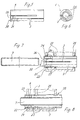
- a dowel 1 is inserted on one side, whereby this dowel 1 is approximately cylindrical and has a profiled lateral surface, for example in the form of knurling or corrugation.
- the dowel 1 has a cylindrical internal thread 5, into which a fastening screw 4 is screwed in.
- a Screwed in expansion screw 7 the thread diameter of which is larger than the thread diameter, d. H. the nominal diameter of the area 6, which corresponds to the Internal thread 5 connects otherwise.
- the expansion screw 7 is preferred designed as a grub screw that is shorter in length than the total length of the internal thread 5 and within that determined by the longitudinal slots 3 Range. That is, the area 6 with a smaller thread diameter than the expansion screw 7 extends up to the end of the longitudinal slots 3, so that a perfect and effective expansion of the anchor is guaranteed.
- area 6 is smaller Thread diameter from its associated end face of the dowel 1, 2 facing Tapered side, so that if necessary when screwing in further the expansion screw 7 is more spread, the thread both this part and the rest of the area 6 in its slope the slope of the Thread of the expansion screw 7 corresponds.
- FIGS. 2 and 3 show the embodiments described above, FIG. 2 showing the dowel 1 and FIG. 3 the dowel 2, the latter with inserted connector 13.
- FIGS. 5 to 8 show a dowel 20 made of metal, in particular for shown a door or window fitting, in which the screw-in expansion screw 7 can be screwed in.
- the dowel 20 designed as a cylindrical sleeve, extends from each end each have two opposing longitudinal slots 3, which extend into the extend into the opposite end region.
- the ones themselves outgoing longitudinal slots 3 lying opposite end sides offset from one another arranged, preferably by 90 ° ( Figure 2).
- the dowel 20 has a region 6, the diameter of which is essentially is consistently smaller than the diameter of the screwed in over the entire length Spreading screw 7, with the same pitch.
- the diameter of the internal thread corresponds only to an insertion region 26 the thread diameter of the expansion screw 7 so that it is screwed in takes effect immediately, for which one or two threads are sufficient.
- both ends of the dowel 20 with such an insertion area 26 be provided, which is advantageous in that the dowel 20 is then practical can be used from any side.
- this end can also have a smooth shaft, the diameter corresponding to the core diameter of the expansion screw 7.
- the expansion screw 7 can perform the function of the fastening screw 4, if it protrudes sufficiently far beyond the dowel 20.
- FIGS. 7 and 8 show the use of a dowel 20 in a hollow chamber profile 22 shown.
- This hollow chamber profile 22 has a plurality of hollow chambers 23, bounded by walls 25 running parallel and at a distance from one another are.
- Through holes 24 are provided, into which the dowel 20 is inserted is, it is dimensioned such that it is on both sides over the last walls 25 protrudes.
- the dowel 20 is one over the entire length Provided external thread 21, which is due to the spreading pressure in the reveal pushes through holes 24 and thus a form fit between the dowel 20 and the hollow chamber profile 22, so that in interaction with the Deformation of the dowel 20 in the other areas an absolutely firm connection is manufactured against pulling out, which also withstands the greatest loads.
- a marking can be provided on the outside of the dowel 20, for example in the form of a profile, such as knurling or the like.
Landscapes
- Engineering & Computer Science (AREA)
- General Engineering & Computer Science (AREA)
- Mechanical Engineering (AREA)
- Dowels (AREA)
- Mutual Connection Of Rods And Tubes (AREA)
Abstract
Description
Stattdessen kann dieses Ende aber auch glattschaftig ausgebildet sein, wobei der Durchmesser dem Kerndurchmesser der Spreizschraube 7 entspricht.
- 1
- Dübel
- 2
- Dübel
- 3
- Längsschlitz
- 4
- Befestigungsschraube
- 5
- Innengewinde
- 6
- Bereich
- 7
- Spreizschraube
- 8
- Endbereich
- 9
- Griffbügel
- 10
- Türblatt
- 11
- Scheibe
- 12
- Aufnahme
- 13
- Verbindungsstück
- 14
- Ringnut
- 15
- Sicherungsschraube
- 16
- Durchgangsbohrung
- 20
- Dübel
- 21
- Außengewinde
- 22
- Hohlkammerprofil
- 23
- Hohlkammer
- 24
- Durchsteckbohrung
- 25
- Wandung
- 26
- Einsteckbereich
Claims (18)
- Dübel mit eindrehbarer Spreizschraube (7), der mindestens einen Längsschlitz (3) aufweist und mit einem Innengewinde (5) versehen ist, in das die Spreizschraube (7) eindrehbar ist, dadurch gekennzeichnet, daß das zylindrische Innengewinde (5) zumindest einen Bereich (6) aufweist, dessen Gewindedurchmesser gleichbleibend kleiner ist als der Gewindedurchmesser der Spreizschraube (7), bei gleicher Gewindesteigung.
- Dübel nach Anspruch 1, dadurch gekennzeichnet, daß die Spreizschraube (7) kürzer ist als die Gesamtlänge des Innengewindes (5).
- Dübel nach Anspruch 1, dadurch gekennzeichnet, daß der Nenndurchmesser der Spreizschraube (7) dem Nenndurchmesser des Innengewindes (5) außerhalb des Bereiches (6) entspricht.
- Dübel nach Anspruch 1, dadurch gekennzeichnet, daß sich der Bereich (6) zur zugeordneten Stirnseite des Dübels (1, 2, 20) hin verjüngt.
- Dübel nach Anspruch 1, dadurch gekennzeichnet, daß dieser eine Aufnahme (12) aufweist, die sich axial über den größten Teil des Innengewindes (5), außerhalb des Bereiches (6), erstreckt.
- Dübel nach Anspruch 5, dadurch gekennzeichnet, daß mindestens eine sich radial von außen bis in die Aufnahme (12) erstreckende Gewindebohrung vorgesehen ist, in die eine Sicherungsschraube (15) eindrehbar ist, die mit einem in die Aufnahme (12) eingesteckten Verbindungsstück (13) korrespondiert.
- Dübel nach Anspruch 5, dadurch gekennzeichnet, daß in das Verbindungsstück (13) eine Befestigungsschraube (4) eindrehbar ist, deren Gewindedurchmesser dem des Innengewindes (5) entspricht.
- Dübel nach Anspruch 1, dadurch gekennzeichnet, daß sich der Bereich (6) im wesentlichen über die gesamte Länge des Dübels (20) erstreckt.
- Dübel nach Anspruch 8, dadurch gekennzeichnet, daß von beiden Enden des Dübels (20) her sich jeweils mindestens ein Längsschlitz (2) erstreckt, die versetzt zueinander angeordnet sind und sich teilweise überlappen.
- Dübel nach Anspruch 9, dadurch gekennzeichnet, daß an jeder Seite des Dübels (20) zwei Längsschlitze (2) vorgesehen sind.
- Dübel nach Anspruch 10, dadurch gekennzeichnet, daß die Längsschlitze (2) jeder Seite sich direkt gegenüber liegen.
- Dübel nach Anspruch 10 oder 11, dadurch gekennzeichnet, daß die Schlitze (2) gleichmäßig zueinander versetzt angeordnet sind.
- Dübel nach Anspruch 8, dadurch gekennzeichnet, daß ein endseitiger Einsteckbereich (26) des Bereiches (6) einen Gewindedurchmesser aufweist, der dem der Spreizschraube (7) entspricht.
- Dübel nach Anspruch 13, dadurch gekennzeichnet, daß an beiden Endseiten des Dübels (20) jeweils ein Einsteckbereich (26) vorgesehen ist.
- Dübel nach Anspruch 13, dadurch gekennzeichnet, daß das einem Einsteckbereich (26) gegenüber liegende Ende innenseitig eine sich nach außen erstreckende Verjüngung aufweist.
- Dübel nach Anspruch 13, dadurch gekennzeichnet, daß das einem Einsteckbereich (26) gegenüber liegende Ende innenseitig glattschaftig ausgebildet ist und einen Durchmesser aufweist, der dem Kerndurchmesser des Innengewindes entspricht.
- Dübel nach Anspruch 13 oder 14, dadurch gekennzeichnet, daß die dem Einsteckbereich (26) zugeordnete Außenseite des Dübels (1) mit einer Markierung in Form einer Profilierung versehen ist.
- Dübel nach Anspruch 1, dadurch gekennzeichnet, daß die Außenseite des Dübels (1, 2, 20) im wesentlichen mit einem Außengewinde (5) versehen ist.
Applications Claiming Priority (2)
| Application Number | Priority Date | Filing Date | Title |
|---|---|---|---|
| DE10052662 | 2000-10-24 | ||
| DE10052662A DE10052662A1 (de) | 2000-10-24 | 2000-10-24 | Dübel mit eindrehbarer Spreizschraube |
Publications (3)
| Publication Number | Publication Date |
|---|---|
| EP1201938A2 true EP1201938A2 (de) | 2002-05-02 |
| EP1201938A3 EP1201938A3 (de) | 2003-05-14 |
| EP1201938B1 EP1201938B1 (de) | 2005-04-06 |
Family
ID=7660867
Family Applications (1)
| Application Number | Title | Priority Date | Filing Date |
|---|---|---|---|
| EP01122717A Expired - Lifetime EP1201938B1 (de) | 2000-10-24 | 2001-09-21 | Dübel mit eindrehbarer Spreizschraube |
Country Status (4)
| Country | Link |
|---|---|
| US (1) | US20020048496A1 (de) |
| EP (1) | EP1201938B1 (de) |
| AT (1) | ATE292756T1 (de) |
| DE (2) | DE10052662A1 (de) |
Cited By (1)
| Publication number | Priority date | Publication date | Assignee | Title |
|---|---|---|---|---|
| WO2014097169A1 (en) | 2012-12-18 | 2014-06-26 | Uab "Zgd Handles" | Wooden door handle |
Families Citing this family (4)
| Publication number | Priority date | Publication date | Assignee | Title |
|---|---|---|---|---|
| DE102009019111B4 (de) | 2009-04-29 | 2016-06-02 | Sonja Maria Bilz | Dübel |
| DE102009026219A1 (de) | 2009-07-22 | 2011-02-03 | Horst Filipp Gmbh | Befestigungseinrichtung |
| DE202011000784U1 (de) | 2011-04-04 | 2011-06-01 | Horst Filipp GmbH, 32130 | Spreizdübel |
| JP7698560B2 (ja) * | 2021-11-12 | 2025-06-25 | Ykk Ap株式会社 | 建具 |
Family Cites Families (6)
| Publication number | Priority date | Publication date | Assignee | Title |
|---|---|---|---|---|
| GB190404735A (en) * | 1904-02-26 | 1905-02-02 | William Edgar Suckling | Improvements in and relating to Means or Apparatus for Securing Holding Screws or the like in Substances. |
| US1248003A (en) * | 1916-09-20 | 1917-11-27 | Henry B Newhall | Bolt-anchor. |
| DE3730860A1 (de) * | 1987-09-15 | 1989-03-30 | Hilti Ag | Spreizduebel |
| DE3927777A1 (de) * | 1989-08-23 | 1991-02-28 | Solvay Werke Gmbh | Weichmacherfreie formmasse auf der basis von polyvinylchlorid, verfahren zur herstellung und verwendung derselben |
| DE3927779A1 (de) * | 1989-08-23 | 1991-02-28 | Fischer Artur Werke Gmbh | Spreizduebel fuer die verankerung in konisch erweiterten bohrloechern |
| AT403402B (de) * | 1995-11-06 | 1998-02-25 | Mark Rudolf | Befestigungselement |
-
2000
- 2000-10-24 DE DE10052662A patent/DE10052662A1/de not_active Ceased
-
2001
- 2001-09-21 AT AT01122717T patent/ATE292756T1/de not_active IP Right Cessation
- 2001-09-21 EP EP01122717A patent/EP1201938B1/de not_active Expired - Lifetime
- 2001-09-21 DE DE50105822T patent/DE50105822D1/de not_active Expired - Fee Related
- 2001-10-15 US US09/977,451 patent/US20020048496A1/en not_active Abandoned
Non-Patent Citations (1)
| Title |
|---|
| None |
Cited By (1)
| Publication number | Priority date | Publication date | Assignee | Title |
|---|---|---|---|---|
| WO2014097169A1 (en) | 2012-12-18 | 2014-06-26 | Uab "Zgd Handles" | Wooden door handle |
Also Published As
| Publication number | Publication date |
|---|---|
| EP1201938B1 (de) | 2005-04-06 |
| DE50105822D1 (de) | 2005-05-12 |
| EP1201938A3 (de) | 2003-05-14 |
| DE10052662A1 (de) | 2002-05-08 |
| ATE292756T1 (de) | 2005-04-15 |
| US20020048496A1 (en) | 2002-04-25 |
Similar Documents
| Publication | Publication Date | Title |
|---|---|---|
| EP0863724B1 (de) | Knochenschraube | |
| EP1239168B1 (de) | Spreizdübel | |
| EP0008085B1 (de) | Ankerbolzen | |
| EP0292742B1 (de) | Distanzschraube | |
| EP0841491B1 (de) | In ein Sackloch einsetzbares Befestigungselement sowie Verfahren zum Setzen eines Befestigungselementes | |
| EP0206327A1 (de) | Vorrichtung zum Verbinden von Rohren | |
| DE19642914C2 (de) | Dübel | |
| DE4210488A1 (de) | Verbindungseinrichtung für ein insbesondere rohrförmiges Bauteil | |
| DE3740460A1 (de) | Selbstbohrende schraube | |
| EP0267161B1 (de) | Schraubvorrichtung | |
| EP1201938B1 (de) | Dübel mit eindrehbarer Spreizschraube | |
| DE19632468A1 (de) | Schraubenanordnung | |
| EP0388694B1 (de) | Spreizdübel | |
| DE4004207A1 (de) | Befestigungsvorrichtung | |
| DE4024963A1 (de) | Duebel mit einer duebelhuelse | |
| DE19956906A1 (de) | Isolierdübel | |
| AT402335B (de) | Justierdübelsystem zur einstellbaren verbindung zweier elemente miteinander sowie eine gewindehülse, eine verankerungshülse, ein verankerungselement und eine bohrhilfe für das justierdübelsystem | |
| DE2452054B2 (de) | Quer zueinander stehendes Paar von Platten aus Holz, Holzspänen o.dgl. mit einer Verbindungsvorrichtung | |
| EP4299930B1 (de) | Verbinder für zwei bauteile | |
| EP0952294B1 (de) | Befestigungsanordnung für Fensterrahmen | |
| CH657679A5 (de) | Spreizduebel. | |
| DE102005030174A1 (de) | Spreizdübel | |
| DE3934534A1 (de) | Spreizduebel | |
| DE20122120U1 (de) | Spreizdübel | |
| DE20018869U1 (de) | Verbindungselement insbesondere für den Möbelbau |
Legal Events
| Date | Code | Title | Description |
|---|---|---|---|
| PUAI | Public reference made under article 153(3) epc to a published international application that has entered the european phase |
Free format text: ORIGINAL CODE: 0009012 |
|
| AK | Designated contracting states |
Kind code of ref document: A2 Designated state(s): AT BE CH CY DE DK ES FI FR GB GR IE IT LI LU MC NL PT SE TR |
|
| AX | Request for extension of the european patent |
Free format text: AL;LT;LV;MK;RO;SI |
|
| PUAL | Search report despatched |
Free format text: ORIGINAL CODE: 0009013 |
|
| RIC1 | Information provided on ipc code assigned before grant |
Ipc: 7F 16B 13/06 A Ipc: 7F 16B 9/02 B Ipc: 7F 16B 13/12 B Ipc: 7E 05B 3/00 B Ipc: 7F 16B 13/02 B |
|
| AK | Designated contracting states |
Designated state(s): AT BE CH CY DE DK ES FI FR GB GR IE IT LI LU MC NL PT SE TR |
|
| AX | Request for extension of the european patent |
Extension state: AL LT LV MK RO SI |
|
| 17P | Request for examination filed |
Effective date: 20030917 |
|
| 17Q | First examination report despatched |
Effective date: 20031020 |
|
| AKX | Designation fees paid |
Designated state(s): AT BE CH CY DE DK ES FI FR GB GR IE IT LI LU MC NL PT SE TR |
|
| GRAP | Despatch of communication of intention to grant a patent |
Free format text: ORIGINAL CODE: EPIDOSNIGR1 |
|
| GRAS | Grant fee paid |
Free format text: ORIGINAL CODE: EPIDOSNIGR3 |
|
| GRAA | (expected) grant |
Free format text: ORIGINAL CODE: 0009210 |
|
| AK | Designated contracting states |
Kind code of ref document: B1 Designated state(s): AT BE CH CY DE DK ES FI FR GB GR IE IT LI LU MC NL PT SE TR |
|
| PG25 | Lapsed in a contracting state [announced via postgrant information from national office to epo] |
Ref country code: IT Free format text: LAPSE BECAUSE OF FAILURE TO SUBMIT A TRANSLATION OF THE DESCRIPTION OR TO PAY THE FEE WITHIN THE PRESCRIBED TIME-LIMIT;WARNING: LAPSES OF ITALIAN PATENTS WITH EFFECTIVE DATE BEFORE 2007 MAY HAVE OCCURRED AT ANY TIME BEFORE 2007. THE CORRECT EFFECTIVE DATE MAY BE DIFFERENT FROM THE ONE RECORDED. Effective date: 20050406 Ref country code: IE Free format text: LAPSE BECAUSE OF FAILURE TO SUBMIT A TRANSLATION OF THE DESCRIPTION OR TO PAY THE FEE WITHIN THE PRESCRIBED TIME-LIMIT Effective date: 20050406 Ref country code: NL Free format text: LAPSE BECAUSE OF FAILURE TO SUBMIT A TRANSLATION OF THE DESCRIPTION OR TO PAY THE FEE WITHIN THE PRESCRIBED TIME-LIMIT Effective date: 20050406 Ref country code: GB Free format text: LAPSE BECAUSE OF FAILURE TO SUBMIT A TRANSLATION OF THE DESCRIPTION OR TO PAY THE FEE WITHIN THE PRESCRIBED TIME-LIMIT Effective date: 20050406 Ref country code: FI Free format text: LAPSE BECAUSE OF FAILURE TO SUBMIT A TRANSLATION OF THE DESCRIPTION OR TO PAY THE FEE WITHIN THE PRESCRIBED TIME-LIMIT Effective date: 20050406 Ref country code: TR Free format text: LAPSE BECAUSE OF FAILURE TO SUBMIT A TRANSLATION OF THE DESCRIPTION OR TO PAY THE FEE WITHIN THE PRESCRIBED TIME-LIMIT Effective date: 20050406 |
|
| REG | Reference to a national code |
Ref country code: GB Ref legal event code: FG4D Free format text: NOT ENGLISH |
|
| REG | Reference to a national code |
Ref country code: CH Ref legal event code: EP |
|
| REG | Reference to a national code |
Ref country code: IE Ref legal event code: FG4D Free format text: LANGUAGE OF EP DOCUMENT: GERMAN |
|
| REF | Corresponds to: |
Ref document number: 50105822 Country of ref document: DE Date of ref document: 20050512 Kind code of ref document: P |
|
| PG25 | Lapsed in a contracting state [announced via postgrant information from national office to epo] |
Ref country code: GR Free format text: LAPSE BECAUSE OF FAILURE TO SUBMIT A TRANSLATION OF THE DESCRIPTION OR TO PAY THE FEE WITHIN THE PRESCRIBED TIME-LIMIT Effective date: 20050706 Ref country code: SE Free format text: LAPSE BECAUSE OF FAILURE TO SUBMIT A TRANSLATION OF THE DESCRIPTION OR TO PAY THE FEE WITHIN THE PRESCRIBED TIME-LIMIT Effective date: 20050706 Ref country code: DK Free format text: LAPSE BECAUSE OF FAILURE TO SUBMIT A TRANSLATION OF THE DESCRIPTION OR TO PAY THE FEE WITHIN THE PRESCRIBED TIME-LIMIT Effective date: 20050706 |
|
| PG25 | Lapsed in a contracting state [announced via postgrant information from national office to epo] |
Ref country code: ES Free format text: LAPSE BECAUSE OF FAILURE TO SUBMIT A TRANSLATION OF THE DESCRIPTION OR TO PAY THE FEE WITHIN THE PRESCRIBED TIME-LIMIT Effective date: 20050717 |
|
| PG25 | Lapsed in a contracting state [announced via postgrant information from national office to epo] |
Ref country code: PT Free format text: LAPSE BECAUSE OF FAILURE TO SUBMIT A TRANSLATION OF THE DESCRIPTION OR TO PAY THE FEE WITHIN THE PRESCRIBED TIME-LIMIT Effective date: 20050908 |
|
| PG25 | Lapsed in a contracting state [announced via postgrant information from national office to epo] |
Ref country code: CY Free format text: LAPSE BECAUSE OF FAILURE TO SUBMIT A TRANSLATION OF THE DESCRIPTION OR TO PAY THE FEE WITHIN THE PRESCRIBED TIME-LIMIT Effective date: 20050921 Ref country code: AT Free format text: LAPSE BECAUSE OF NON-PAYMENT OF DUE FEES Effective date: 20050921 |
|
| PG25 | Lapsed in a contracting state [announced via postgrant information from national office to epo] |
Ref country code: CH Free format text: LAPSE BECAUSE OF NON-PAYMENT OF DUE FEES Effective date: 20050930 Ref country code: MC Free format text: LAPSE BECAUSE OF NON-PAYMENT OF DUE FEES Effective date: 20050930 Ref country code: LI Free format text: LAPSE BECAUSE OF NON-PAYMENT OF DUE FEES Effective date: 20050930 Ref country code: LU Free format text: LAPSE BECAUSE OF NON-PAYMENT OF DUE FEES Effective date: 20050930 Ref country code: BE Free format text: LAPSE BECAUSE OF NON-PAYMENT OF DUE FEES Effective date: 20050930 |
|
| NLV1 | Nl: lapsed or annulled due to failure to fulfill the requirements of art. 29p and 29m of the patents act | ||
| GBV | Gb: ep patent (uk) treated as always having been void in accordance with gb section 77(7)/1977 [no translation filed] |
Effective date: 20050406 |
|
| REG | Reference to a national code |
Ref country code: IE Ref legal event code: FD4D |
|
| PLBE | No opposition filed within time limit |
Free format text: ORIGINAL CODE: 0009261 |
|
| STAA | Information on the status of an ep patent application or granted ep patent |
Free format text: STATUS: NO OPPOSITION FILED WITHIN TIME LIMIT |
|
| 26N | No opposition filed |
Effective date: 20060110 |
|
| REG | Reference to a national code |
Ref country code: CH Ref legal event code: PL |
|
| EN | Fr: translation not filed | ||
| PGFP | Annual fee paid to national office [announced via postgrant information from national office to epo] |
Ref country code: DE Payment date: 20070927 Year of fee payment: 7 |
|
| BERE | Be: lapsed |
Owner name: HORST FILIPP G.M.B.H. Effective date: 20050930 |
|
| PG25 | Lapsed in a contracting state [announced via postgrant information from national office to epo] |
Ref country code: FR Free format text: LAPSE BECAUSE OF NON-PAYMENT OF DUE FEES Effective date: 20050930 |
|
| PG25 | Lapsed in a contracting state [announced via postgrant information from national office to epo] |
Ref country code: FR Free format text: LAPSE BECAUSE OF NON-PAYMENT OF DUE FEES Effective date: 20050406 |
|
| PG25 | Lapsed in a contracting state [announced via postgrant information from national office to epo] |
Ref country code: DE Free format text: LAPSE BECAUSE OF NON-PAYMENT OF DUE FEES Effective date: 20090401 |