EP1201977A2 - Dispositif d'arrêt - Google Patents
Dispositif d'arrêt Download PDFInfo
- Publication number
- EP1201977A2 EP1201977A2 EP01309036A EP01309036A EP1201977A2 EP 1201977 A2 EP1201977 A2 EP 1201977A2 EP 01309036 A EP01309036 A EP 01309036A EP 01309036 A EP01309036 A EP 01309036A EP 1201977 A2 EP1201977 A2 EP 1201977A2
- Authority
- EP
- European Patent Office
- Prior art keywords
- guide device
- housing
- stop
- relative
- sleeve
- Prior art date
- Legal status (The legal status is an assumption and is not a legal conclusion. Google has not performed a legal analysis and makes no representation as to the accuracy of the status listed.)
- Granted
Links
- 230000002093 peripheral effect Effects 0.000 claims description 2
- 238000011109 contamination Methods 0.000 description 1
- 239000012530 fluid Substances 0.000 description 1
- 239000000446 fuel Substances 0.000 description 1
- 238000000034 method Methods 0.000 description 1
Images


Classifications
-
- F—MECHANICAL ENGINEERING; LIGHTING; HEATING; WEAPONS; BLASTING
- F16—ENGINEERING ELEMENTS AND UNITS; GENERAL MEASURES FOR PRODUCING AND MAINTAINING EFFECTIVE FUNCTIONING OF MACHINES OR INSTALLATIONS; THERMAL INSULATION IN GENERAL
- F16K—VALVES; TAPS; COCKS; ACTUATING-FLOATS; DEVICES FOR VENTING OR AERATING
- F16K1/00—Lift valves or globe valves, i.e. cut-off apparatus with closure members having at least a component of their opening and closing motion perpendicular to the closing faces
- F16K1/32—Details
- F16K1/52—Means for additional adjustment of the rate of flow
- F16K1/523—Means for additional adjustment of the rate of flow for limiting the maximum flow rate, using a stop
-
- F—MECHANICAL ENGINEERING; LIGHTING; HEATING; WEAPONS; BLASTING
- F16—ENGINEERING ELEMENTS AND UNITS; GENERAL MEASURES FOR PRODUCING AND MAINTAINING EFFECTIVE FUNCTIONING OF MACHINES OR INSTALLATIONS; THERMAL INSULATION IN GENERAL
- F16K—VALVES; TAPS; COCKS; ACTUATING-FLOATS; DEVICES FOR VENTING OR AERATING
- F16K3/00—Gate valves or sliding valves, i.e. cut-off apparatus with closing members having a sliding movement along the seat for opening and closing
- F16K3/30—Details
- F16K3/32—Means for additional adjustment of the rate of flow
-
- F—MECHANICAL ENGINEERING; LIGHTING; HEATING; WEAPONS; BLASTING
- F02—COMBUSTION ENGINES; HOT-GAS OR COMBUSTION-PRODUCT ENGINE PLANTS
- F02M—SUPPLYING COMBUSTION ENGINES IN GENERAL WITH COMBUSTIBLE MIXTURES OR CONSTITUENTS THEREOF
- F02M21/00—Apparatus for supplying engines with non-liquid fuels, e.g. gaseous fuels stored in liquid form
- F02M21/02—Apparatus for supplying engines with non-liquid fuels, e.g. gaseous fuels stored in liquid form for gaseous fuels
- F02M21/0218—Details on the gaseous fuel supply system, e.g. tanks, valves, pipes, pumps, rails, injectors or mixers
- F02M21/023—Valves; Pressure or flow regulators in the fuel supply or return system
- F02M21/0233—Details of actuators therefor
-
- F—MECHANICAL ENGINEERING; LIGHTING; HEATING; WEAPONS; BLASTING
- F02—COMBUSTION ENGINES; HOT-GAS OR COMBUSTION-PRODUCT ENGINE PLANTS
- F02M—SUPPLYING COMBUSTION ENGINES IN GENERAL WITH COMBUSTIBLE MIXTURES OR CONSTITUENTS THEREOF
- F02M21/00—Apparatus for supplying engines with non-liquid fuels, e.g. gaseous fuels stored in liquid form
- F02M21/02—Apparatus for supplying engines with non-liquid fuels, e.g. gaseous fuels stored in liquid form for gaseous fuels
- F02M21/0218—Details on the gaseous fuel supply system, e.g. tanks, valves, pipes, pumps, rails, injectors or mixers
- F02M21/023—Valves; Pressure or flow regulators in the fuel supply or return system
- F02M21/0239—Pressure or flow regulators therefor
Definitions
- the invention relates to an adjustable stop apparatus for limiting movement of an element of a metering valve for setting a flow limit condition of the valve.
- An adjustable stop apparatus for a metering valve comprising a stop S, a housing H, and a rotary adjuster device D connected to the stop S.
- a rotary adjuster device D connected to the stop S.
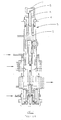
- Such a device is shown in Figure 1 fitted to a metering valve.
- the position of the stop S is normally adjusted by means of the rotary adjuster device D in a factory environment during assembly of the valve, and the rotary adjuster device D is then locked in position with a lock nut N.
- the valve user would not be expected to carry out further adjustments to the position of the stop S of the known device. Therefore, a tamper resistant cover C is generally fitted to the stop apparatus covering the lock nut N.
- an adjustable stop apparatus for limiting movement of an element of a metering valve for setting a flow limit condition of the valve, the apparatus comprising a stop, a housing, a rotary adjuster device connected to the stop for adjustably positioning the stop relative to the housing, and a guide device operable to guide the adjuster device relative to the housing into a plurality of alternative pre-set positions determined by the guide device.
- the guide device releasably secures the adjuster device relative to the housing in said pre-set positions.
- the guide device conveniently comprises a sleeve having a plurality of slots, each slot corresponding to a respective one of set pre-set positions and being selectively alignable with a projection fixed relative to the housing.
- Rotary movement of the adjuster may be permitted by the guide device only within a selected arc between said pre-set positions. This helps prevent confusion when re-positioning the stop, and prevents the adjuster device being turned beyond said pre-set positions resulting in an undesirable stop position.
- a peripheral portion of the sleeve is extended axially beyond the rest of the sleeve to provide a lug which limits the extent of rotary movement of the guide device in its released condition.
- the apparatus further comprises resilient biasing means biasing the guide device in a direction tending to secure the adjuster device relative to the housing.
- the biasing means may comprise a spring disposed within the guide device and acting between an abutment fixed relative to the adjuster device and a laterally inwardly extending portion of the guide device.
- the guide device has an external groove or projection for engagement by a tool, for placing the guide device in a released condition in which the adjuster device is movable relative to the housing, and the housing has a correspondingly positioned access aperture for accessing the groove or projection with the tool.
- Markings may be provided on the guide device for indicating a present position of the guide device, the markings being viewable through the access aperture.
- the markings may include a triangle arranged to indicate, in use, in which direction the guide device should be moved to obtain a greater or lesser flow limit condition of the metering valve.
- the guide device may have a flat sided portion for engagement by a rotary tool, the arrangement being such that the flat sided portion projects from the housing for access by the rotary tool only when the guide device is in the released condition.
- FIG 2 shows an adjustable stop apparatus 1 having a housing 2, a rotary adjuster device 3, and a stop 4 connected to the rotary adjuster device 3.
- the apparatus can be mounted, in use, to a metering valve such as the metering valve shown in Figure 1 for supplying fuel to an engine.
- the stop S can be used for limiting movement of an element of the metering valve for setting a flow limit condition of the valve, for example for setting a maximum flow condition.
- the adjuster device 3 comprises a shaft 7 extending co-axially within the housing 2 and threadedly engaging an internally threaded portion 8 of the housing.
- rotation of the shaft 7 causes the adjuster device 3, and consequently the stop 4, to move axially relative to the housing 2.
- the adjuster device 3 is provided with two axially spaced laterally extending portions 9, 10.
- An 'O' ring seal 11 is housed between the laterally extending portions 9, 10 and an internal face of the housing, for preventing egress of fluid, in use, from a metering valve to which the apparatus 1 is fitted through the interface between the internally threaded portion 8 and corresponding threads on the shaft 7.
- the internally threaded portion 8 comprises a wire thread insert mounted in a through bore in the housing 2, although other ways of providing the internal thread will be apparent to the skilled reader.
- the housing 2 may be fitted to a metering valve, in use, using bolts inserted through holes 12 in laterally extending lugs 13, and a further 'O' ring seal 14 is provided to seal between an external surface of the housing and a surface of the metering valve.
- a guide device is provided, in the form of a sleeve 15 and a laterally inwardly extending projection 16, for guiding the adjuster device 3 relative to the housing into alternative pre-set positions. These positions are determined by axially extending slots 20,21 ( Figures 4 and 5) circumferentially spaced about the sleeve 15, which alternatively engage the projection 16. To engage the projection 16 with one of the slots 20, 21 the sleeve 15 must be lifted so that the previously engaged slot 20, 21 clears the projection 16. The sleeve can then be rotated relative to the housing until the next desired slot 20, 21 is aligned with the projection 16. The sleeve 15 is then moved axially to engage the desired slot 20,21 with the projection 16 to secure the adjuster device 3 relative to the housing 2.
- a circumferential portion of the sleeve 15 between the slots 20, 21 is axially extended so as to provide a lug 22 which extends axially beyond the rest of the sleeve end.
- This lug 22 limits the extent of rotary movement of the sleeve 15, even when the slots 20,21 have been lifted to clear the projection 16. This ensures that the sleeve is not rotated beyond desired limits, whereby engagement of a slot 20,21 with the projection might result in an undesirable position of the stop device.
- an abutment device 25 is inserted internally of the sleeve 15.
- the abutment device 25 has a through passage having internal threads 25a which threadedly engage a threaded portion of the shaft 7.
- the abutment device has a circumferential portion (not shown) which is contoured to engage a laterally inwardly extending projection 26 ( Figure 5) of the sleeve 15 to prevent rotation of the abutment device relative to the sleeve 25.
- the abutment device 25 is secured in position axially on the shaft 7 by a lock nut 27.
- a tamper-proof cover 29 is provided to indicate if any tampering has occurred which might result in any such variable adjustment. Provision of the recessed flats 28 in the shaft 7 assists in keeping the overall length of the assembly 1 to a minimum.
- the tamper-proof cover 29 ensures the integrity of the factory adjusted datum settings. In order further to ensure that the valve is not switched between datum settings in use, it is proposed to wire in place the spring latch which holds the cover 29 in the sleeve 15.
- a resilient biasing means is provided in the form of a helical spring 30 for biasing the sleeve 15 in a direction tending to secure the slot 20 or 21 in engagement with the projection 16.
- One end of the spring 30 abuts a laterally inwardly extending end surface 32 of the sleeve 15 and the other end of the spring 30 abuts a laterally inwardly extending surface 31 of the abutment device 25.
- the length of the spring 30 when fully compressed limits lifting of the sleeve 15 such that the free end of the lug 22 cannot clear the projection 16.
- a groove 35 is provided externally of the sleeve 15.
- An access aperture or window (not shown) is provided in the housing 2 to provide access by a tool, for example a screwdriver, to the groove 35.
- a portion 35a of the sleeve 25 axially adjacent the groove 35 has a slightly reduced outer diameter, so that any slight burrs caused to the portion 35a by engaging the groove 35 with a tool do not hinder free movement of the sleeve 15 relative to the housing 2.
- Markings may be provided on an external surface 36 of the sleeve 15 which are visible through the aperture or window (not shown).
- the markings may comprise respective letters which are fully visible when a respective one of the slots 20, 21 is fully engaged with the projection 16.
- the markings may also comprise a triangle disposed between the letters, indicating whether the change of position being effected will result in a greater or lesser maximum flow condition of the metering valve to which the apparatus 1 is to be fitted.
- the sleeve 15 has external flats 37 provided at one end thereof which extend axially from the housing 2 only when the sleeve 15 has been fully lifted against the biasing force of the spring 30. In this condition, the flats 37 can be engaged by a tool to assist in turning the sleeve 15 to the other pre-set position.
- the projection 16 may be a pin brazed to the housing 2.
- the apparatus 1 allows the position of the stop 4 to be adjusted with the apparatus 1 fitted to a metering valve, without removing components from the metering valve. This facility is useful in practice in preventing internal contamination of the metering valve during adjustment between the two maximum flow settings.
Landscapes
- Engineering & Computer Science (AREA)
- General Engineering & Computer Science (AREA)
- Mechanical Engineering (AREA)
- Physics & Mathematics (AREA)
- Fluid Mechanics (AREA)
- Preventing Unauthorised Actuation Of Valves (AREA)
- Measuring Volume Flow (AREA)
- Mechanically-Actuated Valves (AREA)
Applications Claiming Priority (2)
| Application Number | Priority Date | Filing Date | Title |
|---|---|---|---|
| GBGB0026061.2A GB0026061D0 (en) | 2000-10-25 | 2000-10-25 | Adjustable stop apparatus |
| GB0026061 | 2000-10-25 |
Publications (3)
| Publication Number | Publication Date |
|---|---|
| EP1201977A2 true EP1201977A2 (fr) | 2002-05-02 |
| EP1201977A3 EP1201977A3 (fr) | 2003-07-09 |
| EP1201977B1 EP1201977B1 (fr) | 2006-04-26 |
Family
ID=9901912
Family Applications (1)
| Application Number | Title | Priority Date | Filing Date |
|---|---|---|---|
| EP01309036A Expired - Lifetime EP1201977B1 (fr) | 2000-10-25 | 2001-10-24 | Dispositif d'arrêt |
Country Status (4)
| Country | Link |
|---|---|
| US (1) | US6729602B2 (fr) |
| EP (1) | EP1201977B1 (fr) |
| DE (1) | DE60119061T2 (fr) |
| GB (1) | GB0026061D0 (fr) |
Families Citing this family (9)
| Publication number | Priority date | Publication date | Assignee | Title |
|---|---|---|---|---|
| US7481413B2 (en) * | 2004-06-14 | 2009-01-27 | Zurn Industries, Llc | Flush actuator assembly and method therefor |
| WO2006121905A2 (fr) | 2005-05-06 | 2006-11-16 | Belimo Holding Ag | Ensemble soupape de commande reglable sur place et module de reglable sur place |
| US7607635B2 (en) * | 2005-08-25 | 2009-10-27 | Sloan Valve Company | Flush valve handle assembly providing dual mode operation |
| AU2007217354B2 (en) * | 2006-02-27 | 2011-03-31 | Sloan Valve Company | Dual flush activation |
| US7621461B2 (en) * | 2006-08-18 | 2009-11-24 | Flow Design, Inc. | System and method for regulating heat transfer on a fluid by regulating the flow of the fluid |
| TWI390097B (zh) | 2006-09-29 | 2013-03-21 | Sloan Valve Co | 用於控制沖流閥或沖流計的沖流容積之方法及系統 |
| EP2813628B1 (fr) | 2013-03-15 | 2019-02-27 | Sloane Valve Company | Commande de chasse à double mode |
| EP2813627A1 (fr) | 2013-03-15 | 2014-12-17 | Sloan Valve Company | Actionneur de chasse d'eau automatique comprenant une commande manuelle additionelle |
| WO2019164700A1 (fr) * | 2018-02-22 | 2019-08-29 | Swagelok Company | Dispositif de régulation de débit à mécanisme de réglage de débit |
Family Cites Families (6)
| Publication number | Priority date | Publication date | Assignee | Title |
|---|---|---|---|---|
| FR845170A (fr) | 1937-10-25 | 1939-08-14 | Procédé de réglage des installations de chauffage par la vapeur | |
| GB757779A (en) | 1953-11-03 | 1956-09-26 | Sulzer Ag | Flow control valves |
| US3397863A (en) * | 1966-05-18 | 1968-08-20 | Standard Screw | Adjustable stop tube |
| US4342443A (en) * | 1979-10-26 | 1982-08-03 | Colt Industries Operating Corp | Multi-stage fuel metering valve assembly |
| DE9404344U1 (de) | 1994-02-07 | 1994-06-09 | Gampper Gmbh, 67821 Alsenz | Thermostatventil mit Voreinstellung der Durchflußmenge |
| US5904336A (en) * | 1996-04-15 | 1999-05-18 | Emhart Inc. | Valve assembly |
-
2000
- 2000-10-25 GB GBGB0026061.2A patent/GB0026061D0/en not_active Ceased
-
2001
- 2001-10-23 US US10/000,513 patent/US6729602B2/en not_active Expired - Lifetime
- 2001-10-24 EP EP01309036A patent/EP1201977B1/fr not_active Expired - Lifetime
- 2001-10-24 DE DE60119061T patent/DE60119061T2/de not_active Expired - Lifetime
Non-Patent Citations (1)
| Title |
|---|
| None |
Also Published As
| Publication number | Publication date |
|---|---|
| DE60119061T2 (de) | 2006-11-30 |
| US20020047102A1 (en) | 2002-04-25 |
| DE60119061D1 (de) | 2006-06-01 |
| EP1201977A3 (fr) | 2003-07-09 |
| US6729602B2 (en) | 2004-05-04 |
| EP1201977B1 (fr) | 2006-04-26 |
| GB0026061D0 (en) | 2000-12-13 |
Similar Documents
| Publication | Publication Date | Title |
|---|---|---|
| US4126023A (en) | Tamperproof locking and latching mechanism for rotatable controls | |
| EP1201977B1 (fr) | Dispositif d'arrêt | |
| EP2469139B1 (fr) | Dispositif de retour d'information | |
| SE460217B (sv) | Anordning foer snabbverkande, manuell fraankoppling av ett elektriskt manoevrerbart organ i en ventil | |
| US3945302A (en) | Diaphragm adjustment tool | |
| US5236172A (en) | Lockout modules | |
| DE102016106181B4 (de) | Absperrarmatur | |
| EP0140275A2 (fr) | Levier à main pour mitigeur monocommande | |
| EP1469242B1 (fr) | Poignées pour soupapes | |
| US5074134A (en) | Lockable adjustment mechanism | |
| EP0502090A1 (fr) | Dispositif de reglage de vanne. | |
| US12601408B2 (en) | Control valve | |
| US4450697A (en) | Security devices for rotatable members and fluid flow control valves incorporating such devices | |
| EP0246359B1 (fr) | Vanne thermostatique pour le réfrigérant d'un moteur à combustion interne | |
| EP0027898B1 (fr) | Dispositif pour le réglage de l'alimentation en gaz | |
| US4381797A (en) | Flow control valve with a non-rising stem | |
| DE3509353C1 (de) | Regeleinrichtung für ein Thermostatventil | |
| DE202025100452U1 (de) | Steuerknopf zur manuellen Feineinstellung von Einrichtung sowie Werkzeug für die Montage eines solchen Steuerknopfs | |
| EP0168154A2 (fr) | Dispositif de verrouillage | |
| EP0414970A1 (fr) | Capteur de position avec cames ajustables angulairement | |
| EP0366722A1 (fr) | Dispositif de commande de carburant | |
| EP0073862B1 (fr) | Dispositif de sécurité pour des éléments tournantes et obturateurs de commande de fluide équipés d'un tel dispositif | |
| US4907779A (en) | Electro-magnetically operated valve devices | |
| EP0123320B1 (fr) | Dispositif ajustable de commande pour un compteur de gaz à diaphragme | |
| US3289696A (en) | Tamper-proof control for a by-pass type meter bar |
Legal Events
| Date | Code | Title | Description |
|---|---|---|---|
| PUAI | Public reference made under article 153(3) epc to a published international application that has entered the european phase |
Free format text: ORIGINAL CODE: 0009012 |
|
| AK | Designated contracting states |
Kind code of ref document: A2 Designated state(s): AT BE CH CY DE DK ES FI FR GB GR IE IT LI LU MC NL PT SE TR |
|
| AX | Request for extension of the european patent |
Free format text: AL;LT;LV;MK;RO;SI |
|
| PUAL | Search report despatched |
Free format text: ORIGINAL CODE: 0009013 |
|
| AK | Designated contracting states |
Designated state(s): AT BE CH CY DE DK ES FI FR GB GR IE IT LI LU MC NL PT SE TR |
|
| AX | Request for extension of the european patent |
Extension state: AL LT LV MK RO SI |
|
| RAP1 | Party data changed (applicant data changed or rights of an application transferred) |
Owner name: GOODRICH CONTROL SYSTEMS LIMITED |
|
| 17P | Request for examination filed |
Effective date: 20031117 |
|
| AKX | Designation fees paid |
Designated state(s): DE FR GB IT |
|
| 17Q | First examination report despatched |
Effective date: 20040223 |
|
| GRAP | Despatch of communication of intention to grant a patent |
Free format text: ORIGINAL CODE: EPIDOSNIGR1 |
|
| GRAS | Grant fee paid |
Free format text: ORIGINAL CODE: EPIDOSNIGR3 |
|
| GRAA | (expected) grant |
Free format text: ORIGINAL CODE: 0009210 |
|
| RIN1 | Information on inventor provided before grant (corrected) |
Inventor name: HANKIN, ALON G. S. Inventor name: JONES, ROBERT PAUL |
|
| AK | Designated contracting states |
Kind code of ref document: B1 Designated state(s): DE FR GB IT |
|
| PG25 | Lapsed in a contracting state [announced via postgrant information from national office to epo] |
Ref country code: IT Free format text: LAPSE BECAUSE OF FAILURE TO SUBMIT A TRANSLATION OF THE DESCRIPTION OR TO PAY THE FEE WITHIN THE PRESCRIBED TIME-LIMIT;WARNING: LAPSES OF ITALIAN PATENTS WITH EFFECTIVE DATE BEFORE 2007 MAY HAVE OCCURRED AT ANY TIME BEFORE 2007. THE CORRECT EFFECTIVE DATE MAY BE DIFFERENT FROM THE ONE RECORDED. Effective date: 20060426 |
|
| REG | Reference to a national code |
Ref country code: GB Ref legal event code: FG4D |
|
| REF | Corresponds to: |
Ref document number: 60119061 Country of ref document: DE Date of ref document: 20060601 Kind code of ref document: P |
|
| ET | Fr: translation filed | ||
| PLBE | No opposition filed within time limit |
Free format text: ORIGINAL CODE: 0009261 |
|
| STAA | Information on the status of an ep patent application or granted ep patent |
Free format text: STATUS: NO OPPOSITION FILED WITHIN TIME LIMIT |
|
| 26N | No opposition filed |
Effective date: 20070129 |
|
| REG | Reference to a national code |
Ref country code: DE Ref legal event code: R081 Ref document number: 60119061 Country of ref document: DE Owner name: GOODRICH CONTROL SYSTEMS, GB Free format text: FORMER OWNER: GOODRICH CONTROL SYSTEMS LTD., LUTON, GB Effective date: 20140220 Ref country code: DE Ref legal event code: R081 Ref document number: 60119061 Country of ref document: DE Owner name: GOODRICH CONTROL SYSTEMS, SOLIHULL, GB Free format text: FORMER OWNER: GOODRICH CONTROL SYSTEMS LTD., LUTON, BEDFORDSHIRE, GB Effective date: 20140220 |
|
| REG | Reference to a national code |
Ref country code: FR Ref legal event code: CJ Effective date: 20140313 Ref country code: FR Ref legal event code: CD Owner name: GOODRICH CONTROL SYSTEMS Effective date: 20140313 |
|
| REG | Reference to a national code |
Ref country code: FR Ref legal event code: PLFP Year of fee payment: 16 |
|
| REG | Reference to a national code |
Ref country code: FR Ref legal event code: PLFP Year of fee payment: 17 |
|
| PGFP | Annual fee paid to national office [announced via postgrant information from national office to epo] |
Ref country code: GB Payment date: 20170925 Year of fee payment: 17 Ref country code: FR Payment date: 20170921 Year of fee payment: 17 |
|
| PGFP | Annual fee paid to national office [announced via postgrant information from national office to epo] |
Ref country code: DE Payment date: 20170920 Year of fee payment: 17 |
|
| REG | Reference to a national code |
Ref country code: DE Ref legal event code: R119 Ref document number: 60119061 Country of ref document: DE |
|
| GBPC | Gb: european patent ceased through non-payment of renewal fee |
Effective date: 20181024 |
|
| PG25 | Lapsed in a contracting state [announced via postgrant information from national office to epo] |
Ref country code: DE Free format text: LAPSE BECAUSE OF NON-PAYMENT OF DUE FEES Effective date: 20190501 |
|
| PG25 | Lapsed in a contracting state [announced via postgrant information from national office to epo] |
Ref country code: FR Free format text: LAPSE BECAUSE OF NON-PAYMENT OF DUE FEES Effective date: 20181031 |
|
| PG25 | Lapsed in a contracting state [announced via postgrant information from national office to epo] |
Ref country code: GB Free format text: LAPSE BECAUSE OF NON-PAYMENT OF DUE FEES Effective date: 20181024 |