EP1201980A2 - Dispositif de maintien pour lignes d'alimentation aux bâtiments - Google Patents
Dispositif de maintien pour lignes d'alimentation aux bâtiments Download PDFInfo
- Publication number
- EP1201980A2 EP1201980A2 EP01870228A EP01870228A EP1201980A2 EP 1201980 A2 EP1201980 A2 EP 1201980A2 EP 01870228 A EP01870228 A EP 01870228A EP 01870228 A EP01870228 A EP 01870228A EP 1201980 A2 EP1201980 A2 EP 1201980A2
- Authority
- EP
- European Patent Office
- Prior art keywords
- spine
- supporting means
- bearer
- spring clip
- tongues
- Prior art date
- Legal status (The legal status is an assumption and is not a legal conclusion. Google has not performed a legal analysis and makes no representation as to the accuracy of the status listed.)
- Withdrawn
Links
Images



Classifications
-
- F—MECHANICAL ENGINEERING; LIGHTING; HEATING; WEAPONS; BLASTING
- F16—ENGINEERING ELEMENTS AND UNITS; GENERAL MEASURES FOR PRODUCING AND MAINTAINING EFFECTIVE FUNCTIONING OF MACHINES OR INSTALLATIONS; THERMAL INSULATION IN GENERAL
- F16L—PIPES; JOINTS OR FITTINGS FOR PIPES; SUPPORTS FOR PIPES, CABLES OR PROTECTIVE TUBING; MEANS FOR THERMAL INSULATION IN GENERAL
- F16L3/00—Supports for pipes, cables or protective tubing, e.g. hangers, holders, clamps, cleats, clips, brackets
- F16L3/006—Supports for pipes, cables or protective tubing, e.g. hangers, holders, clamps, cleats, clips, brackets for pipes with a rectangular cross-section
-
- F—MECHANICAL ENGINEERING; LIGHTING; HEATING; WEAPONS; BLASTING
- F16—ENGINEERING ELEMENTS AND UNITS; GENERAL MEASURES FOR PRODUCING AND MAINTAINING EFFECTIVE FUNCTIONING OF MACHINES OR INSTALLATIONS; THERMAL INSULATION IN GENERAL
- F16L—PIPES; JOINTS OR FITTINGS FOR PIPES; SUPPORTS FOR PIPES, CABLES OR PROTECTIVE TUBING; MEANS FOR THERMAL INSULATION IN GENERAL
- F16L3/00—Supports for pipes, cables or protective tubing, e.g. hangers, holders, clamps, cleats, clips, brackets
- F16L3/24—Supports for pipes, cables or protective tubing, e.g. hangers, holders, clamps, cleats, clips, brackets with special member for attachment to profiled girders
- F16L3/245—Supports for pipes, cables or protective tubing, e.g. hangers, holders, clamps, cleats, clips, brackets with special member for attachment to profiled girders the special member embracing the entire profiled girder
-
- F—MECHANICAL ENGINEERING; LIGHTING; HEATING; WEAPONS; BLASTING
- F16—ENGINEERING ELEMENTS AND UNITS; GENERAL MEASURES FOR PRODUCING AND MAINTAINING EFFECTIVE FUNCTIONING OF MACHINES OR INSTALLATIONS; THERMAL INSULATION IN GENERAL
- F16L—PIPES; JOINTS OR FITTINGS FOR PIPES; SUPPORTS FOR PIPES, CABLES OR PROTECTIVE TUBING; MEANS FOR THERMAL INSULATION IN GENERAL
- F16L3/00—Supports for pipes, cables or protective tubing, e.g. hangers, holders, clamps, cleats, clips, brackets
- F16L3/26—Supports for pipes, cables or protective tubing, e.g. hangers, holders, clamps, cleats, clips, brackets specially adapted for supporting the pipes all along their length, e.g. pipe channels or ducts
-
- H—ELECTRICITY
- H02—GENERATION; CONVERSION OR DISTRIBUTION OF ELECTRIC POWER
- H02G—INSTALLATION OF ELECTRIC CABLES OR LINES, OR OF COMBINED OPTICAL AND ELECTRIC CABLES OR LINES
- H02G3/00—Installations of electric cables or lines or protective tubing therefor in or on buildings, equivalent structures or vehicles
- H02G3/02—Details
- H02G3/04—Protective tubing or conduits, e.g. cable ladders or cable troughs
- H02G3/0456—Ladders or other supports
-
- H—ELECTRICITY
- H02—GENERATION; CONVERSION OR DISTRIBUTION OF ELECTRIC POWER
- H02G—INSTALLATION OF ELECTRIC CABLES OR LINES, OR OF COMBINED OPTICAL AND ELECTRIC CABLES OR LINES
- H02G3/00—Installations of electric cables or lines or protective tubing therefor in or on buildings, equivalent structures or vehicles
- H02G3/30—Installations of cables or lines on walls, floors or ceilings
- H02G3/32—Installations of cables or lines on walls, floors or ceilings using mounting clamps
-
- H—ELECTRICITY
- H02—GENERATION; CONVERSION OR DISTRIBUTION OF ELECTRIC POWER
- H02G—INSTALLATION OF ELECTRIC CABLES OR LINES, OR OF COMBINED OPTICAL AND ELECTRIC CABLES OR LINES
- H02G3/00—Installations of electric cables or lines or protective tubing therefor in or on buildings, equivalent structures or vehicles
- H02G3/26—Installations of cables, lines, or separate protective tubing therefor directly on or in walls, ceilings, or floors
- H02G3/263—Installation, e.g. suspension, of conduit channels or other supports
-
- Y—GENERAL TAGGING OF NEW TECHNOLOGICAL DEVELOPMENTS; GENERAL TAGGING OF CROSS-SECTIONAL TECHNOLOGIES SPANNING OVER SEVERAL SECTIONS OF THE IPC; TECHNICAL SUBJECTS COVERED BY FORMER USPC CROSS-REFERENCE ART COLLECTIONS [XRACs] AND DIGESTS
- Y10—TECHNICAL SUBJECTS COVERED BY FORMER USPC
- Y10T—TECHNICAL SUBJECTS COVERED BY FORMER US CLASSIFICATION
- Y10T24/00—Buckles, buttons, clasps, etc.
- Y10T24/44—Clasp, clip, support-clamp, or required component thereof
- Y10T24/44017—Clasp, clip, support-clamp, or required component thereof with specific mounting means for attaching to rigid or semirigid supporting structure or structure-to-be-secured
-
- Y—GENERAL TAGGING OF NEW TECHNOLOGICAL DEVELOPMENTS; GENERAL TAGGING OF CROSS-SECTIONAL TECHNOLOGIES SPANNING OVER SEVERAL SECTIONS OF THE IPC; TECHNICAL SUBJECTS COVERED BY FORMER USPC CROSS-REFERENCE ART COLLECTIONS [XRACs] AND DIGESTS
- Y10—TECHNICAL SUBJECTS COVERED BY FORMER USPC
- Y10T—TECHNICAL SUBJECTS COVERED BY FORMER US CLASSIFICATION
- Y10T24/00—Buckles, buttons, clasps, etc.
- Y10T24/44—Clasp, clip, support-clamp, or required component thereof
- Y10T24/44641—Clasp, clip, support-clamp, or required component thereof having gripping member formed from, biased by, or mounted on resilient member
- Y10T24/44769—Opposed engaging faces on gripping member formed from single piece of resilient material
-
- Y—GENERAL TAGGING OF NEW TECHNOLOGICAL DEVELOPMENTS; GENERAL TAGGING OF CROSS-SECTIONAL TECHNOLOGIES SPANNING OVER SEVERAL SECTIONS OF THE IPC; TECHNICAL SUBJECTS COVERED BY FORMER USPC CROSS-REFERENCE ART COLLECTIONS [XRACs] AND DIGESTS
- Y10—TECHNICAL SUBJECTS COVERED BY FORMER USPC
- Y10T—TECHNICAL SUBJECTS COVERED BY FORMER US CLASSIFICATION
- Y10T403/00—Joints and connections
- Y10T403/60—Biased catch or latch
- Y10T403/606—Leaf spring
Definitions
- This invention relates to supporting means for elongated building services supply means.
- service supply means may be electric power cables, communication cables, water or gas pipes or other elongated means for the supply or distribution of services within a building.
- Such supporting means necessarily include one or more bearer elements on which the service supply means rest.
- the bearer element has been the floor of a tray or trough fixedly associated with the building being serviced, for example carried by wall brackets or suspended from a ceiling or other overhead building component by tie rods or the like.
- the bearer elements of cable trays comprised the floor of a shallow trough or elongated tray.
- the service supply means resided within the trough.
- the trough including its floor was constructed from sheet material, for example steel, plastics or fibrous cement.
- At least the floor of the trough has been made of expanded metal sheet. This is preferred as it eliminates the possibility of the trough retaining water or detritus that may be damaging to the service supply means.
- floor-like bearer elements came to be replaced by a plurality of spaced apart rungs extending between rigid stiles.
- the wall brackets or tie rods are affixed to the stiles, so that the supporting means as a whole resemble a conventional ladder in a substantially horizontal disposition.
- Such ladder-like supporting means are still customarily referred to as cable trays.
- the stiles of such ladder-like cable trays have been replaced by a central spine, and the rungs by a plurality of spaced apart bearer elements extending as cantilevers from each side of the spine.
- the bearer elements preferably have upturned free end parts, so as to retain the service supply means. This is advantageous as the service supply means may be placed on the bearer elements from the sides, instead of having to be pulled into position from one end of the cable tray.
- An object of the present invention is to alleviate the aforesaid disadvantage of the prior art.
- a further object is to provide for the on-site selection of the spacing between discrete bearer elements to suit the degree of pliability of the service supply means in any instance.
- the invention is well adapted for use in relation to cable trays comprising a single spine and a plurality of discrete cantilever bearer elements, although it will be apparent to the skilled addressee that it is also applicable to ladder-like cable trays having two or more parallel spines and a plurality of discrete rung-like bearer elements.
- the invention in its broadest aspect, consists in supporting means for elongated building service supply means of the kind comprising at least one spine and a plurality of discrete bearer elements affixed to said at least one spine, characterised in that each bearer element is affixed to said at least one spine by a spring clip fixedly associated with said each bearer element.
- the spring clip is formed integrally with its associated bearer element.
- the invention consists in supporting means according to the first aspect wherein there are at least an equal plurality of locating formations on said spine each able to be engaged by a co-acting locating formation on a said spring clip to thereafter resist disengagement of the bearer elements from the spine.
- the spine is an inverted channel section comprising a channel web and two channel flanges, said locating formations comprise a longitudinally extending row of spaced apart holes in each of the channel flanges, each spring clip comprises two upwardly directed, spaced apart resilient tongues projecting from the clip's associated bearer element, each with a barb formation at or near its free end directed towards the other and each with a stud intermediate its ends projecting towards the other constituting said co-acting locating formations; the arrangement being such that the tongues of each clip may clasp the spine between them with the barbs of the tongues overlying respective margins of the channel web and with the studs on each tongue extending into a respective hole in the adjacent channel flange.
- each bearer element defines a groove at or near the root of each of its tongues in which a free edge margin of the adjacent channel flange is received when the barb formations overlie the margins of the channel web and the studs are homed in the holes.
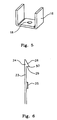
- the supporting means illustrated by the drawings comprises a spine 10 and a plurality of bearer elements 11 spaced along the spine 10, of which only one appears in the drawings.
- the spine 10 is a length of inverted channel section comprising a channel web 12 and two channel flanges 13. It may be roll or press formed from sheet steel, preferably coated with a rust resistant alloy, for example an aluminium-zinc alloy.
- a rust resistant alloy for example an aluminium-zinc alloy.
- the flanges 13 possess a degree of resilience, such that their free edges may be elastically pressed towards each to a limited extent, as shown in figure 7, but will return to their original position when the loading pressure is relaxed, as shown in figure 9.
- the spine 10 is furnished with clip locating formations in the form of equally spaced apart holes 14, arranged in rows extending along the respective flanges 13.
- the spine 10 may be suspended by two or more threaded tie rods 15, of which only one appears in the drawings, extending downwardly from any appropriate, fixed, overhead component of the building being serviced.
- the spine 10 may be secured to each tie rod 15 by means of a U-shaped saddle 16 into which the spine 10 neatly sits.
- the channel web 12 is pierced by a plurality of clearance holes 17 and the saddle 16 is likewise pierced by a clearance hole 18.
- the tie rod 15 extends through a selected hole 17 and the hole 18.
- the saddle 16 may then be supported by a nut and washer 19 on the tie rod, bearing against the underface of the saddle 16. If desired, the affixture of the spine to the tie rod may be made more secure by a second nut and washer 19 on the tie rod, bearing against the upper face of the web 12.
- the spine 10 is provided to the user in lengths that are a whole number multiple of the modular dimension, and the centre distances between holes 17 and holes 14 are that such one or a whole number plurality of such centre distances equals the modular dimension applicable to the building being serviced.
- the bearer element 11 is preferably a moulded plastics item, for example of glass-filled nylon. It comprises two cantilever arms 20 with upturned ends 21 and an integral, central resilient clip 22.
- the clip 22 comprises two, upwardly directed, resilient tongues 23. Each is furnished with a barb formation 24 at its free end, and a protruding stud 25 intermediate its ends. Each stud 25 is dimensioned to fit neatly into any of the holes 14.
- each barb formation 24 presents an inclined upper face 28 and a horizontal under face 29. Those faces meet at a contact line 30. It should also be noted that the barb formation 24 projects substantially further from the tongue 23 than does the stud 25.
- the clip 22 further comprises two beads 26 near, but spaced from, the roots of the tongues 23.
- at least the upper margins of the faces of the beads 26 opposed to the tongues 23 are inclined, so that they and the bottom margins of the respectively adjacent tongues define two grooves 27 which are somewhat wider at the top than they are at the bottom.
- the grooves 27 are dimensioned so that the free end margins of the flanges 13 are a neat fit within the bottom parts of the grooves 27.
- the bearer element 11 becomes very firmly affixed to the spine 10, at least insofar as downward loads on the bearer element are concerned, in that the studs 25 are within the holes 14, the flanges 13 are prevented from moving apart to free the studs 25, by the web 12 at one end and the beads 26 at the other end, and there are no contacting surfaces producing any reaction loading on the tongues tending to separate them.
Landscapes
- Engineering & Computer Science (AREA)
- General Engineering & Computer Science (AREA)
- Mechanical Engineering (AREA)
- Architecture (AREA)
- Civil Engineering (AREA)
- Structural Engineering (AREA)
- Supports For Pipes And Cables (AREA)
- Installation Of Indoor Wiring (AREA)
- Details Of Indoor Wiring (AREA)
- Electric Cable Installation (AREA)
Applications Claiming Priority (2)
| Application Number | Priority Date | Filing Date | Title |
|---|---|---|---|
| AU69622/00A AU6962200A (en) | 2000-10-30 | 2000-10-30 | Supporting means for elongated building services supply means |
| AU6962200 | 2000-10-30 |
Publications (2)
| Publication Number | Publication Date |
|---|---|
| EP1201980A2 true EP1201980A2 (fr) | 2002-05-02 |
| EP1201980A3 EP1201980A3 (fr) | 2003-11-05 |
Family
ID=3753089
Family Applications (1)
| Application Number | Title | Priority Date | Filing Date |
|---|---|---|---|
| EP01870228A Withdrawn EP1201980A3 (fr) | 2000-10-30 | 2001-10-29 | Dispositif de maintien pour lignes d'alimentation aux bâtiments |
Country Status (8)
| Country | Link |
|---|---|
| US (1) | US6729585B2 (fr) |
| EP (1) | EP1201980A3 (fr) |
| JP (1) | JP2002233024A (fr) |
| AU (1) | AU6962200A (fr) |
| BR (1) | BR0105695A (fr) |
| CA (1) | CA2360141A1 (fr) |
| NZ (1) | NZ515065A (fr) |
| SG (1) | SG97210A1 (fr) |
Cited By (7)
| Publication number | Priority date | Publication date | Assignee | Title |
|---|---|---|---|---|
| GB2374611B (en) * | 2001-04-21 | 2003-10-29 | Marlow & Company Ltd | Improvements in and relating to flooring |
| EP1722161A2 (fr) | 2005-05-11 | 2006-11-15 | Hella KG Hueck & Co. | Projecteur de type elliptique pour véhicules |
| EP2738045A1 (fr) * | 2012-12-01 | 2014-06-04 | MAN Truck & Bus AG | Dispositif de fixation |
| WO2014133935A1 (fr) * | 2013-02-27 | 2014-09-04 | Panduit Corp. | Ensemble support pour échelon d'échelle |
| CN106090431A (zh) * | 2016-08-16 | 2016-11-09 | 江苏迪威高压科技股份有限公司 | 一种石油管件 |
| GB2539378A (en) * | 2015-05-06 | 2016-12-21 | Ellis Patents Holdings Ltd | Apparatus and method for supporting an elongate object |
| CN112217169A (zh) * | 2020-09-23 | 2021-01-12 | 安徽华希电力科技有限公司 | 一种操作方便并带有传感器的三心电缆卡具 |
Families Citing this family (26)
| Publication number | Priority date | Publication date | Assignee | Title |
|---|---|---|---|---|
| FR2829525B1 (fr) * | 2001-09-13 | 2004-03-12 | Snecma Moteurs | Assemblage de secteurs d'un distributeur de turbine a un carter |
| FR2838792B1 (fr) * | 2002-04-18 | 2004-10-29 | Plastic Omnium Cie | Dispositif de fixation d'un organe fonctionnel sur une piece de structure de vehicule automobile et piece de structure integrant partiellement un tel dispositif |
| US6786301B2 (en) * | 2002-06-08 | 2004-09-07 | Robin Nesburg | Scaffold system |
| JP4040374B2 (ja) * | 2002-07-04 | 2008-01-30 | キヤノン株式会社 | カバーユニット及び記録装置 |
| US20060080933A1 (en) * | 2004-10-14 | 2006-04-20 | Fci Americas Technology, Inc. | Multi-rung supporting means for elongated building services supply means |
| US7562421B2 (en) * | 2005-04-03 | 2009-07-21 | Magen Eco Energy A.C.S. Ltd. | Connecting clasp |
| US20070231099A1 (en) * | 2006-03-28 | 2007-10-04 | Rick Bryant | Anchor for a cable support structure |
| US7640701B2 (en) * | 2006-11-10 | 2010-01-05 | Flannery Inc. | Deflection clip |
| WO2008076713A2 (fr) * | 2006-12-14 | 2008-06-26 | Meier Franz X | Appareil et système d'aplanissement pour panneau tridimensionnel |
| DE102007062855B3 (de) * | 2007-12-21 | 2009-02-19 | Ae & E Lentjes Gmbh | Rohrhalterung, insbesondere für Rohrleitungen in Rauchgasabsorbern |
| US20100213337A1 (en) * | 2009-02-23 | 2010-08-26 | Fergin Earl G | Mounting assembly |
| US8327591B2 (en) * | 2010-03-24 | 2012-12-11 | Wilkinson Jr Edgar L | Overhead panel and installation system |
| USD730164S1 (en) * | 2012-09-19 | 2015-05-26 | J2 Product Development, LLC | Shower curtain closure device |
| US10407985B2 (en) | 2014-03-25 | 2019-09-10 | Panduit Corp. | Cradle clamp bracket assembly |
| US9587433B2 (en) | 2014-03-25 | 2017-03-07 | Panduit Corp. | Cradle clamp bracket assembly |
| US9810021B2 (en) | 2014-05-30 | 2017-11-07 | Panduit Corp. | Thermal expansion and contraction system |
| US10744662B2 (en) * | 2015-12-17 | 2020-08-18 | Bic-Violex Sa | Shaving head |
| US10913172B2 (en) * | 2015-12-17 | 2021-02-09 | Bic-Violex Sa | Shaving head |
| US10989335B2 (en) * | 2016-03-30 | 2021-04-27 | Zsi, Inc. | Saddle pipe support |
| CN106427539B (zh) * | 2016-11-01 | 2019-04-05 | 中国重汽集团济南动力有限公司 | 一种轻型汽车用油管固定支架总成 |
| KR101788843B1 (ko) | 2017-06-08 | 2017-10-20 | 주식회사지티엘이엔지 | 화재경고기능을 구비한 공동주택용 배전선 설치트레이 |
| KR101809734B1 (ko) | 2017-06-08 | 2017-12-15 | 주식회사지티엘이엔지 | 공동주택용 전선지지대 |
| KR101848848B1 (ko) | 2017-09-26 | 2018-04-16 | 주식회사 토문엔지니어링건축사사무소 | 케이블설치가 용이한 건축물용 전기 케이블 트레이 |
| US11906089B2 (en) | 2022-05-28 | 2024-02-20 | The Boeing Company | Co-molded snap-on support base, and support system and method of using the same |
| US12275359B2 (en) | 2023-06-16 | 2025-04-15 | The Boeing Company | One-piece co-molded snap-on apparatus, and support system and method of using the same |
| US12117108B1 (en) | 2024-02-29 | 2024-10-15 | Sunmodo Corporation | Rail-pipe brackets, pipe clamps, and related components for supporting solar panels |
Family Cites Families (15)
| Publication number | Priority date | Publication date | Assignee | Title |
|---|---|---|---|---|
| US749222A (en) * | 1904-01-12 | S sheetsxsheet z | ||
| US718545A (en) * | 1900-03-17 | 1903-01-13 | Herbert A Streeter | Metal clip for use in steel building constructions. |
| US656274A (en) * | 1900-03-17 | 1900-08-21 | Herbert A Streeter | Clip for steel building construction, & c. |
| GB624188A (en) * | 1946-12-19 | 1949-05-30 | Allan Robert Blackwood | An improved clip or fastening |
| US3036801A (en) * | 1959-04-07 | 1962-05-29 | Western Electric Co | Wire support device |
| US3161263A (en) * | 1961-01-19 | 1964-12-15 | United States Steel Corp | Object supporting assembly |
| US3485467A (en) * | 1967-04-26 | 1969-12-23 | Bell Telephone Labor Inc | Telephone wire pair clip |
| US5123618A (en) * | 1991-09-16 | 1992-06-23 | Guterman Douglas E | Cable tray |
| CA2083034A1 (fr) * | 1991-11-18 | 1993-05-19 | Isidore Handler | Support antisismique pour chemin de cables electriques |
| US5564658A (en) | 1993-12-29 | 1996-10-15 | B-Line Systems, Inc. | Support system for data transmission lines |
| US5730400A (en) * | 1995-09-01 | 1998-03-24 | Sigma-Aldrich | Cable tray cover system |
| AUPO380096A0 (en) | 1996-11-25 | 1996-12-19 | Ramset Fasteners (Aust.) Pty. Limited | Cable support system |
| US6198047B1 (en) * | 1999-02-08 | 2001-03-06 | Charles Barr | Cable tray with power channel |
| EP1074773A1 (fr) * | 1999-08-03 | 2001-02-07 | Thomas & Betts International, Inc. | Collier de support de câble et dispositif de fixation associé |
| FR2801439B1 (fr) * | 1999-11-24 | 2001-12-14 | Mavil | Procede d'assemblage d'un chemin de cables et ensemble de troncons allonges formant un tel chemin de cables |
-
2000
- 2000-10-30 AU AU69622/00A patent/AU6962200A/en not_active Abandoned
-
2001
- 2001-10-23 SG SG200106529A patent/SG97210A1/en unknown
- 2001-10-25 CA CA002360141A patent/CA2360141A1/fr not_active Abandoned
- 2001-10-26 US US10/033,106 patent/US6729585B2/en not_active Expired - Fee Related
- 2001-10-26 NZ NZ515065A patent/NZ515065A/en unknown
- 2001-10-29 BR BR0105695-6A patent/BR0105695A/pt not_active Application Discontinuation
- 2001-10-29 EP EP01870228A patent/EP1201980A3/fr not_active Withdrawn
- 2001-10-30 JP JP2001333380A patent/JP2002233024A/ja active Pending
Cited By (13)
| Publication number | Priority date | Publication date | Assignee | Title |
|---|---|---|---|---|
| GB2374611B (en) * | 2001-04-21 | 2003-10-29 | Marlow & Company Ltd | Improvements in and relating to flooring |
| EP1722161A2 (fr) | 2005-05-11 | 2006-11-15 | Hella KG Hueck & Co. | Projecteur de type elliptique pour véhicules |
| EP2738045A1 (fr) * | 2012-12-01 | 2014-06-04 | MAN Truck & Bus AG | Dispositif de fixation |
| US9719300B2 (en) | 2013-02-27 | 2017-08-01 | Panduit Corp. | Ladder rung bracket assembly |
| CN105075040A (zh) * | 2013-02-27 | 2015-11-18 | 泛达公司 | 梯级支架组件 |
| US9309719B2 (en) | 2013-02-27 | 2016-04-12 | Panduit Corp. | Ladder rung bracket assembly |
| CN105075040B (zh) * | 2013-02-27 | 2017-07-21 | 泛达公司 | 梯级支架组件 |
| WO2014133935A1 (fr) * | 2013-02-27 | 2014-09-04 | Panduit Corp. | Ensemble support pour échelon d'échelle |
| US10246941B2 (en) | 2013-02-27 | 2019-04-02 | Panduit Corp. | Ladder rung bracket assembly |
| GB2539378A (en) * | 2015-05-06 | 2016-12-21 | Ellis Patents Holdings Ltd | Apparatus and method for supporting an elongate object |
| GB2539378B (en) * | 2015-05-06 | 2020-12-09 | Ellis Patents Holdings Ltd | Apparatus and method for supporting an elongate object |
| CN106090431A (zh) * | 2016-08-16 | 2016-11-09 | 江苏迪威高压科技股份有限公司 | 一种石油管件 |
| CN112217169A (zh) * | 2020-09-23 | 2021-01-12 | 安徽华希电力科技有限公司 | 一种操作方便并带有传感器的三心电缆卡具 |
Also Published As
| Publication number | Publication date |
|---|---|
| AU6962200A (en) | 2002-05-02 |
| JP2002233024A (ja) | 2002-08-16 |
| CA2360141A1 (fr) | 2002-04-30 |
| US20030006347A1 (en) | 2003-01-09 |
| BR0105695A (pt) | 2002-09-17 |
| SG97210A1 (en) | 2003-07-18 |
| NZ515065A (en) | 2002-03-01 |
| EP1201980A3 (fr) | 2003-11-05 |
| US6729585B2 (en) | 2004-05-04 |
Similar Documents
| Publication | Publication Date | Title |
|---|---|---|
| EP1201980A2 (fr) | Dispositif de maintien pour lignes d'alimentation aux bâtiments | |
| US11339571B2 (en) | Ceiling system | |
| AU2009250953B2 (en) | Panels and systems of such panels for instance for suspended ceilings | |
| EP1885566B1 (fr) | Clip pour suspendre une paire de poutres en T parallèles | |
| US4041668A (en) | Clip structure for a concealed grid structure of a suspended ceiling | |
| US4128979A (en) | Suspension assembly for partition panel | |
| US20080236068A1 (en) | Drywall channel with pre-punched locating tabs | |
| US5423507A (en) | Bracket for holding ceiling suspended fixtures | |
| US20030080259A1 (en) | Combined safety clip and closure for a conductor support | |
| US20060080933A1 (en) | Multi-rung supporting means for elongated building services supply means | |
| US6505796B1 (en) | Hanger assembly for hanging elongated members from a support | |
| US6213678B1 (en) | Hanger apparatus | |
| DE102022110103B3 (de) | Befestigungsklammer für ein Kabeltragsystem sowie Kabeltragsystem mit einer solchen Befestigungsklammer | |
| EP0607707A2 (fr) | Plafond suspendu | |
| DE19829127A1 (de) | Befestigungselement zum Anbringen U-förmiger Tragprofile an einem Verankerungsgrund | |
| KR19980011876U (ko) | 스위치박스 고정장치 | |
| HK1117110B (en) | Paired main tee clip | |
| NZ500862A (en) | Ceiling panel support system including parallel main runners supporting tiles and interconnected by transverse struts obscured by the tiles |
Legal Events
| Date | Code | Title | Description |
|---|---|---|---|
| PUAI | Public reference made under article 153(3) epc to a published international application that has entered the european phase |
Free format text: ORIGINAL CODE: 0009012 |
|
| AK | Designated contracting states |
Kind code of ref document: A2 Designated state(s): AT BE CH CY DE DK ES FI FR GB GR IE IT LI LU MC NL PT SE TR |
|
| AX | Request for extension of the european patent |
Free format text: AL;LT;LV;MK;RO;SI |
|
| PUAL | Search report despatched |
Free format text: ORIGINAL CODE: 0009013 |
|
| AK | Designated contracting states |
Kind code of ref document: A3 Designated state(s): AT BE CH CY DE DK ES FI FR GB GR IE IT LI LU MC NL PT SE TR |
|
| AX | Request for extension of the european patent |
Extension state: AL LT LV MK RO SI |
|
| AKX | Designation fees paid |
Designated state(s): AT BE CH CY DE DK ES FI FR GB GR IE IT LI LU MC NL PT SE TR |
|
| 17P | Request for examination filed |
Effective date: 20040623 |
|
| 17Q | First examination report despatched |
Effective date: 20041005 |
|
| STAA | Information on the status of an ep patent application or granted ep patent |
Free format text: STATUS: THE APPLICATION IS DEEMED TO BE WITHDRAWN |
|
| 18D | Application deemed to be withdrawn |
Effective date: 20050216 |