EP1201982A2 - Raccord de tuyau - Google Patents
Raccord de tuyau Download PDFInfo
- Publication number
- EP1201982A2 EP1201982A2 EP01250382A EP01250382A EP1201982A2 EP 1201982 A2 EP1201982 A2 EP 1201982A2 EP 01250382 A EP01250382 A EP 01250382A EP 01250382 A EP01250382 A EP 01250382A EP 1201982 A2 EP1201982 A2 EP 1201982A2
- Authority
- EP
- European Patent Office
- Prior art keywords
- pipe connection
- connection according
- section
- cylindrical section
- ring
- Prior art date
- Legal status (The legal status is an assumption and is not a legal conclusion. Google has not performed a legal analysis and makes no representation as to the accuracy of the status listed.)
- Withdrawn
Links
Images



Classifications
-
- F—MECHANICAL ENGINEERING; LIGHTING; HEATING; WEAPONS; BLASTING
- F16—ENGINEERING ELEMENTS AND UNITS; GENERAL MEASURES FOR PRODUCING AND MAINTAINING EFFECTIVE FUNCTIONING OF MACHINES OR INSTALLATIONS; THERMAL INSULATION IN GENERAL
- F16L—PIPES; JOINTS OR FITTINGS FOR PIPES; SUPPORTS FOR PIPES, CABLES OR PROTECTIVE TUBING; MEANS FOR THERMAL INSULATION IN GENERAL
- F16L13/00—Non-disconnectable pipe joints, e.g. soldered, adhesive, or caulked joints
- F16L13/14—Non-disconnectable pipe joints, e.g. soldered, adhesive, or caulked joints made by plastically deforming the material of the pipe, e.g. by flanging, rolling
- F16L13/141—Non-disconnectable pipe joints, e.g. soldered, adhesive, or caulked joints made by plastically deforming the material of the pipe, e.g. by flanging, rolling by crimping or rolling from the outside
- F16L13/142—Non-disconnectable pipe joints, e.g. soldered, adhesive, or caulked joints made by plastically deforming the material of the pipe, e.g. by flanging, rolling by crimping or rolling from the outside with a sealing element inserted into the female part before crimping or rolling
-
- F—MECHANICAL ENGINEERING; LIGHTING; HEATING; WEAPONS; BLASTING
- F16—ENGINEERING ELEMENTS AND UNITS; GENERAL MEASURES FOR PRODUCING AND MAINTAINING EFFECTIVE FUNCTIONING OF MACHINES OR INSTALLATIONS; THERMAL INSULATION IN GENERAL
- F16L—PIPES; JOINTS OR FITTINGS FOR PIPES; SUPPORTS FOR PIPES, CABLES OR PROTECTIVE TUBING; MEANS FOR THERMAL INSULATION IN GENERAL
- F16L37/00—Couplings of the quick-acting type
- F16L37/08—Couplings of the quick-acting type in which the connection between abutting or axially overlapping ends is maintained by locking members
- F16L37/084—Couplings of the quick-acting type in which the connection between abutting or axially overlapping ends is maintained by locking members combined with automatic locking
- F16L37/091—Couplings of the quick-acting type in which the connection between abutting or axially overlapping ends is maintained by locking members combined with automatic locking by means of a ring provided with teeth or fingers
Definitions
- the invention relates to a pipe connection consisting of a press fitting and a pipe insertable therein according to the preamble of Claim 1.
- the sealing function of the connection is achieved that by plastic deformation of the bead-like end of the sealing ring is elastically deformed and over a certain part of the cross-sectional circumference linear on the surrounding surface areas of the bulge trained end of the press fitting and the pipe come to rest.
- Another pipe connection is known from JP 55-88939. It consists of one Press fitting that has at least one sealing ring with a bead-like cross section receiving section and an adjoining the insertion side facing first cylindrical portion. On the other A second cylindrical section is provided on the side of the annular bead, which is smaller in inner diameter so that it forms a stop. The transition from the annular bead to the second cylindrical section takes place via a Jumping point, which merge into the two adjacent areas. The jump point serves as a guide for the inserted pipe. The smooth end of the pipe to be connected comes after Push in at the stop of the second cylindrical section Investment.
- press jaws comprising the press fitting having pressing tool after closing the pressing jaws Inseparable, tight pipe connection formed, the during the pressing Press jaws both on the ring bead including the sealing ring inserted therein, as also act on the first cylindrical section of the press fitting.
- a disadvantage of the known solutions is the arrangement of the return movement of the inserted pipe preventing agent outside the Area of action of the press jaw.
- the object of the invention is to provide a pipe connection that previously does not have the disadvantage explained.
- this is the return movement of the inserted Pipe preventing agent arranged in the area of action of the press jaw.
- the agent is made of an elastic material manufactured ring trained.
- the agent can be a spring element from a metallic material or from plastic or from a composite material metal-plastic be made.
- the Ring or the nose of the ring inclined in the direction of insertion.
- it can Means in the cylindrical facing or facing away from the insertion side trained section may be arranged.
- the desired aggravation of the return movement can be achieved in which you slightly reduce the inner diameter towards the insertion side. Thereby a quasi cone is formed, which forms the stop at its narrowest point.
- the agent can also be applied the inside of the flank area of the ring bead or alternatively in the sealing ring be arranged.
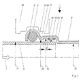
- FIG. 1 one half of a longitudinal section is designed according to the invention Pipe connection shown. It consists of a press fitting 1 with an outside extending annular bead 2 and a sealing ring 3 inserted therein, and one in the press fitting 1 inserted pipe 4.
- Ring bead 2 via a flank 5 in a cylindrical lying in the insertion direction 7 Section 6 about.
- the insertion direction 7 is marked with an arrow.
- the Cylindrical section 6.1 forms a at the end of its extension Jump point 8, which then merges into another cylindrical one Section 9.
- the inner diameter 10 of the latter cylindrical section 9 is less than the smallest outer diameter 11 of the tolerance inserted pipe 4.
- cylindrically shaped Section 6.1 is according to the invention the return movement of the inserted Line tube 4 inhibiting means arranged.
- it is a ring 12 made of a metallic material, with several on the circumference arranged lugs 13. These lugs 13 are inclined in the insertion direction 7.
- the cylindrical section 6.1 has a Inner diameter 14, which is larger than the inner diameter 15 in the transition Ring bead 2 - cylindrical section 6.1.
- the arrangement of the ring 12 according to the invention is the partial area of a press jaw 16 been drawn in. From this it can be seen that the ring 12 in the area of action of the press web 17 is arranged. This means that when pressing the ring 12 is deformed with and the lugs 13 in the underlying conduit 4th be pushed in. So that the axial securing against pressing out inserted pipe 4 reinforced.
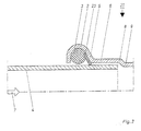
- Figure 2 shows a second embodiment of the designed according to the invention Pipe connection, the same reference numerals being used for the same parts are.
- the Insertion direction 7 side facing a cylindrical portion 6.2 arranged. It is comparable to section 6.1 in FIG. 1 and is designed the return movement of the inserted pipe 4 preventing ring 12 is in ordered him. The return movement is marked by a distance x.
- a paragraph 18 forms a stop for further backward movement. This area can also comparable to that shown in Figure 5, with a cone whose narrowest point forms the stop.
- FIG. 3 A further embodiment is shown in FIG. 3, likewise for identical parts the same reference numerals have been used.
- this is the Back movement preventing means in the form of a cone ring 23 on the inside the flank 5 of the press fitting 21 is arranged.
- the edge 5 forms the transition from the annular bead 2 to the cylindrical section 6.
- the cone ring 23 is in Insertion direction 7 inclined.
- FIG. 3 comparable to Figure 2 with two cylindrical sections 6, right and can be formed to the left of the annular bead 2.
- FIG. 4 Another embodiment is shown in FIG. 4.
- the means preventing the return movement of the inserted conduit 4 is also arranged in the form of a conical ring 23 in the sealing ring 3.
- this embodiment can be designed as in FIG. 3 with the same arrangement of the conical ring 22 in the sealing ring 3. LIST OF REFERENCE NUMBERS No.
Landscapes
- Engineering & Computer Science (AREA)
- General Engineering & Computer Science (AREA)
- Mechanical Engineering (AREA)
- Quick-Acting Or Multi-Walled Pipe Joints (AREA)
- Non-Disconnectible Joints And Screw-Threaded Joints (AREA)
Applications Claiming Priority (2)
| Application Number | Priority Date | Filing Date | Title |
|---|---|---|---|
| DE10054367 | 2000-10-30 | ||
| DE2000154367 DE10054367A1 (de) | 2000-10-30 | 2000-10-30 | Rohrverbindung |
Publications (2)
| Publication Number | Publication Date |
|---|---|
| EP1201982A2 true EP1201982A2 (fr) | 2002-05-02 |
| EP1201982A3 EP1201982A3 (fr) | 2003-06-04 |
Family
ID=7661943
Family Applications (1)
| Application Number | Title | Priority Date | Filing Date |
|---|---|---|---|
| EP01250382A Withdrawn EP1201982A3 (fr) | 2000-10-30 | 2001-10-30 | Raccord de tuyau |
Country Status (2)
| Country | Link |
|---|---|
| EP (1) | EP1201982A3 (fr) |
| DE (1) | DE10054367A1 (fr) |
Cited By (8)
| Publication number | Priority date | Publication date | Assignee | Title |
|---|---|---|---|---|
| EP1424523A1 (fr) * | 2002-11-27 | 2004-06-02 | Mapress GmbH & Co. KG | Raccord de tuyaux |
| EP1431643A1 (fr) * | 2002-12-18 | 2004-06-23 | Franz Viegener II GmbH & Co. KG. | Raccord à sertissage et élément de retenue pour un raccord à sertissage |
| EP1593898A1 (fr) * | 2004-05-07 | 2005-11-09 | VIEGA GmbH & Co. KG. | Elément d'étanchéité |
| CN100429449C (zh) * | 2004-06-17 | 2008-10-29 | 章根友 | 管子的连接结构 |
| US20100025992A1 (en) * | 2008-08-01 | 2010-02-04 | Nibco Inc. | Crimp evident seal |
| DE102009007303A1 (de) * | 2009-02-03 | 2010-08-19 | Viega Gmbh & Co. Kg | Fitting für dickwandige Rohre und Verfahren zu dessen Herstellung |
| CN102679057A (zh) * | 2012-05-23 | 2012-09-19 | 深圳雅昌管业有限公司 | 高防渗性金属挤压式管件连接工艺方法 |
| US12060954B2 (en) | 2019-03-26 | 2024-08-13 | Nibco Inc. | Piping component and sealing element for insertion therein |
Families Citing this family (4)
| Publication number | Priority date | Publication date | Assignee | Title |
|---|---|---|---|---|
| DE10207201A1 (de) * | 2002-02-21 | 2003-09-04 | Welcker F | Pressfitting |
| DE202004007291U1 (de) * | 2004-05-07 | 2005-09-15 | Viega Gmbh & Co Kg | Pressverbindungsanordnung |
| DE102005015278B4 (de) * | 2005-03-29 | 2010-06-10 | Geberit International Ag | Rohrverbindung |
| DE102006008317B4 (de) * | 2006-02-17 | 2008-07-03 | Geberit Technik Ag, Jona | Rohrverbindung |
Citations (3)
| Publication number | Priority date | Publication date | Assignee | Title |
|---|---|---|---|---|
| JPS5588939A (en) | 1978-12-27 | 1980-07-05 | Nippon Benkan Kogyo Kk | Joint connection method |
| DE19631574C1 (de) | 1996-07-26 | 1997-11-13 | Mannesmann Ag | Rohrverbindung |
| WO1999049255A1 (fr) | 1998-03-24 | 1999-09-30 | Mapress Gmbh & Co. Kg | Raccord de tuyaux |
Family Cites Families (1)
| Publication number | Priority date | Publication date | Assignee | Title |
|---|---|---|---|---|
| JPH0259130A (ja) * | 1988-07-13 | 1990-02-28 | Mie Horo Kk | 管材の接合方法 |
-
2000
- 2000-10-30 DE DE2000154367 patent/DE10054367A1/de not_active Withdrawn
-
2001
- 2001-10-30 EP EP01250382A patent/EP1201982A3/fr not_active Withdrawn
Patent Citations (3)
| Publication number | Priority date | Publication date | Assignee | Title |
|---|---|---|---|---|
| JPS5588939A (en) | 1978-12-27 | 1980-07-05 | Nippon Benkan Kogyo Kk | Joint connection method |
| DE19631574C1 (de) | 1996-07-26 | 1997-11-13 | Mannesmann Ag | Rohrverbindung |
| WO1999049255A1 (fr) | 1998-03-24 | 1999-09-30 | Mapress Gmbh & Co. Kg | Raccord de tuyaux |
Cited By (13)
| Publication number | Priority date | Publication date | Assignee | Title |
|---|---|---|---|---|
| EP1424523A1 (fr) * | 2002-11-27 | 2004-06-02 | Mapress GmbH & Co. KG | Raccord de tuyaux |
| EP1431643A1 (fr) * | 2002-12-18 | 2004-06-23 | Franz Viegener II GmbH & Co. KG. | Raccord à sertissage et élément de retenue pour un raccord à sertissage |
| EP1593898A1 (fr) * | 2004-05-07 | 2005-11-09 | VIEGA GmbH & Co. KG. | Elément d'étanchéité |
| US7201382B2 (en) | 2004-05-07 | 2007-04-10 | Viega Gmbh & Co. Kg | Sealing element |
| CN100429449C (zh) * | 2004-06-17 | 2008-10-29 | 章根友 | 管子的连接结构 |
| US9188260B2 (en) * | 2008-08-01 | 2015-11-17 | Nibco Inc. | Crimp evident seal |
| US20100025992A1 (en) * | 2008-08-01 | 2010-02-04 | Nibco Inc. | Crimp evident seal |
| DE102009007303A1 (de) * | 2009-02-03 | 2010-08-19 | Viega Gmbh & Co. Kg | Fitting für dickwandige Rohre und Verfahren zu dessen Herstellung |
| US8517431B2 (en) | 2009-02-03 | 2013-08-27 | Viega Gmbh & Co. Kg | Fitting for thick-walled pipes and method for its production |
| US9234611B2 (en) | 2009-02-03 | 2016-01-12 | Viega Gmbh & Co. Kg | Fitting for thick-walled pipes and method for its production |
| DE102009007303B4 (de) | 2009-02-03 | 2023-05-04 | Viega Technology Gmbh & Co. Kg | Fitting für dickwandige Rohre |
| CN102679057A (zh) * | 2012-05-23 | 2012-09-19 | 深圳雅昌管业有限公司 | 高防渗性金属挤压式管件连接工艺方法 |
| US12060954B2 (en) | 2019-03-26 | 2024-08-13 | Nibco Inc. | Piping component and sealing element for insertion therein |
Also Published As
| Publication number | Publication date |
|---|---|
| EP1201982A3 (fr) | 2003-06-04 |
| DE10054367A1 (de) | 2002-05-08 |
Similar Documents
| Publication | Publication Date | Title |
|---|---|---|
| DE19631574C1 (de) | Rohrverbindung | |
| AT401417B (de) | Schiebehülsen-verbindung für kunststoffrohre | |
| DE3602499C2 (fr) | ||
| DE69002047T2 (de) | Rohrkupplung. | |
| DE29803195U1 (de) | Kombination aus einer Steckverbindung für Rohrleitungen und einem Lösewerkzeug | |
| EP0501404A1 (fr) | Dispositif de raccordement pour tuyaux en matière plastique et méthode pour raccorder un tuyau en matière plastique | |
| EP0925467B1 (fr) | Douille de fixation pour flexible | |
| EP1201982A2 (fr) | Raccord de tuyau | |
| DE202020102046U1 (de) | Rohrleitungsverbindungsstruktur | |
| DE19813805C1 (de) | Rohrverbindung | |
| DE202007007827U1 (de) | Klemmfitting für ein Rohr | |
| DE10118955C2 (de) | Rohrverbindung | |
| EP1489344A2 (fr) | Combinaison d'une pièce de raccord à sertir avec un outil de sertissage, pièce de raccord à sertir et douille de sertissage | |
| DE10125304C1 (de) | Rohrverbindung | |
| DE2233103A1 (de) | Rohrverbindung sowie verfahren und verbindungshuelse zur herstellung der rohrverbindung | |
| DE4211959C2 (fr) | ||
| DE973290C (de) | Rohrverbindung | |
| DE10002916C1 (de) | Pressfittingelement | |
| DE19852861C1 (de) | Rohrpreßverbindung | |
| DE102005015278B4 (de) | Rohrverbindung | |
| DE102004007112B3 (de) | Vorrichtung zum Prüfen des Innenmaßes einer Pressverbindung | |
| DE19856766C1 (de) | Rohrpreßverbindung | |
| DE10026083C1 (de) | Rohrpressverbindung | |
| EP1347226B1 (fr) | Raccord de tuyau | |
| EP1331427B1 (fr) | Raccord ou garniture pour établir un raccordement serré avec un embout tubulaire emboité |
Legal Events
| Date | Code | Title | Description |
|---|---|---|---|
| PUAI | Public reference made under article 153(3) epc to a published international application that has entered the european phase |
Free format text: ORIGINAL CODE: 0009012 |
|
| AK | Designated contracting states |
Kind code of ref document: A2 Designated state(s): AT BE CH CY DE DK ES FI FR GB GR IE IT LI LU MC NL PT SE TR |
|
| AX | Request for extension of the european patent |
Free format text: AL;LT;LV;MK;RO;SI |
|
| PUAL | Search report despatched |
Free format text: ORIGINAL CODE: 0009013 |
|
| AK | Designated contracting states |
Designated state(s): AT BE CH CY DE DK ES FI FR GB GR IE IT LI LU MC NL PT SE TR |
|
| AX | Request for extension of the european patent |
Extension state: AL LT LV MK RO SI |
|
| RIC1 | Information provided on ipc code assigned before grant |
Ipc: 7F 16L 13/16 B Ipc: 7F 16L 13/14 A |
|
| 17P | Request for examination filed |
Effective date: 20030903 |
|
| AKX | Designation fees paid |
Designated state(s): AT BE CH CY DE DK ES FI FR GB GR IE IT LI LU MC NL PT SE TR |
|
| RAP1 | Party data changed (applicant data changed or rights of an application transferred) |
Owner name: GEBERIT MAPRESS GMBH |
|
| STAA | Information on the status of an ep patent application or granted ep patent |
Free format text: STATUS: THE APPLICATION HAS BEEN WITHDRAWN |
|
| 18W | Application withdrawn |
Effective date: 20050104 |