EP1202001A2 - Ventilateur soufflant pour un système de conditionnement d'air - Google Patents
Ventilateur soufflant pour un système de conditionnement d'air Download PDFInfo
- Publication number
- EP1202001A2 EP1202001A2 EP01124334A EP01124334A EP1202001A2 EP 1202001 A2 EP1202001 A2 EP 1202001A2 EP 01124334 A EP01124334 A EP 01124334A EP 01124334 A EP01124334 A EP 01124334A EP 1202001 A2 EP1202001 A2 EP 1202001A2
- Authority
- EP
- European Patent Office
- Prior art keywords
- blower
- supports
- entry ring
- entry
- standing
- Prior art date
- Legal status (The legal status is an assumption and is not a legal conclusion. Google has not performed a legal analysis and makes no representation as to the accuracy of the status listed.)
- Withdrawn
Links
Images


Classifications
-
- F—MECHANICAL ENGINEERING; LIGHTING; HEATING; WEAPONS; BLASTING
- F24—HEATING; RANGES; VENTILATING
- F24F—AIR-CONDITIONING; AIR-HUMIDIFICATION; VENTILATION; USE OF AIR CURRENTS FOR SCREENING
- F24F7/00—Ventilation
- F24F7/007—Ventilation with forced flow
-
- F—MECHANICAL ENGINEERING; LIGHTING; HEATING; WEAPONS; BLASTING
- F04—POSITIVE - DISPLACEMENT MACHINES FOR LIQUIDS; PUMPS FOR LIQUIDS OR ELASTIC FLUIDS
- F04D—NON-POSITIVE-DISPLACEMENT PUMPS
- F04D29/00—Details, component parts, or accessories
- F04D29/40—Casings; Connections of working fluid
- F04D29/42—Casings; Connections of working fluid for radial or helico-centrifugal pumps
- F04D29/4206—Casings; Connections of working fluid for radial or helico-centrifugal pumps especially adapted for elastic fluid pumps
- F04D29/4213—Casings; Connections of working fluid for radial or helico-centrifugal pumps especially adapted for elastic fluid pumps suction ports
Definitions
- the present invention relates to a blower arrangement for use in a Air conditioning system, e.g. is used for copying / duplicating machines.
- Air conditioning systems usually include a blower system that helps them the cleaned and cooled air or another gas is available for use in the apparatus close.
- An air conditioning system is a precisely working, expensive subsystem in one Copy / duplicating machine. It is important to increase the efficiency of the air conditioning system get and improve as possible while continuously improving and Cost reduction measures are carried out.
- the air conditioning system uses one or more Air filter chambers, which include one or more blower systems.
- the used Blower systems increase the air pressure in the chamber (s) so that the air passes through filters is pressed to remove particles. The filtered air is then from the blower system out of the machine and / or for reuse in other parts of the machine guided.
- the attachment of the blower itself within the blower arrangement of the Air conditioning system is of particular importance.
- the blower arrangement has an entry ring through which the air is drawn into the blower and then from the blower into the desired direction (s) within the air conditioning system.
- the fan should be as close to Entry ring.
- the space between the flow direction Subsequent entry edge of the entry ring and the blower itself should be approximately 0.15 cm (0.06 inch) with the gap tolerance no more than about 0.05 cm (0.02 Inches) should be. If the gap is too small, there is a risk that Fan hits the inlet ring during operation. However, if the gap is too large, leads this to air turbulence. Both affect the operating efficiency and the lifespan of the Machine.
- blow assemblies have been made from a variety of items, as later is described in more detail.
- the assembly of these parts was time consuming and expensive.
- the Blower arrangement for copying / duplicating machines, for example, based on the following 1 and 2 is a welded construction of five parts.
- the present invention provides an improved fan assembly that does the above listed requirements.
- This invention also provides an improved one Entry ring with entry ring support unit ready, which enables a blower arrangement, the to meet the above requirements.
- the blower arrangement according to the invention uses an inlet ring with an integrated one Entry ring support element, which consists of a single part.
- the entry ring support element also has a number of integrated standing supports or columns that are used to Blowers are aligned and have a free end. Every support comes from Back of the support element and ends in a free end.
- the supports and their free ends define the volume of space or the area in which the fan operates.
- a blower support element is attached to the ends of the supports, including a lower one Closure element that is located on the lower side of the blower between the Blower support element and the entry ring support element is located.
- blower arrangement is further characterized in that, in contrast to the prior art has no side elements provided with openings. This is shown in detail in the description of the prior art.
- the unit consisting of the entry ring and the entry ring support element is a single, integrated component in contrast to the two individual parts according to the prior art, the one Make manual assembly necessary.
- This component also has a variety of standing Supports that are part of the entrance ring support surface and each have a free end to have. These supports and their free ends define the volume of space or the area in which the blower can be operated.
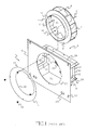
- FIG. 1 shows a blower arrangement 1 for an air conditioning system according to the prior art Technology that a blower i.e. a fan 4, a pre-assembled blower housing 6 and a separate, i.e. includes non-built entry ring 5.
- a blower i.e. a fan 4
- a pre-assembled blower housing 6 i.e. includes non-built entry ring 5.
- the blower 4 is composed of a first support element 7 with a blower cable holder 2 and a second support element 9 located at a distance from it. Between Support elements 7 and 9, a large number of blades 8 is attached. On the second support element 9 is an upstanding air inlet baffle 11, through which through which the air is drawn in the direction of arrow 16 into the interior 15 of the blower 4 becomes.
- the steering plate 11 has a diameter which is approximately that in the flow direction subordinate inner diameter of the air inlet ring 5 corresponds. The outer edge 11 ' this steering plate defines in cooperation with the downstream entry edge 14 of the Entry ring 5 the above Gap between the inlet ring and the blower itself, whose width must be set to approx. 0.15 cm.
- the entry ring 5 has an outer diameter, which is defined by the edge 13, and an inner diameter defined by the rim 14.
- the inner diameter of the edge 14 is smaller than the outer diameter of the edge 13.
- the blower housing 6, which consists of several different items, as already in 1 are composed, consists of an entry ring support element 3, a separate fan support element 18, an open top 19, a separate bottom Closure element 21 and the separate, provided with the openings 23 and 25 respectively Side elements 22 and 24.
- the fan 4 is in the inner space 12, which by the above. Blower housing elements 6 is defined, appropriate.
- the entry ring 5 is by means of screws 10 on the separate Entry ring support element 3 attached so that it can also be detached therefrom.
- the Ring 5 fits the ring support opening 20, the diameter of which is between the outer Diameter of the entry ring defined by rim 13 and its inner diameter, defined by edge 14.
- blower housing 6 according to the prior art, with individual Has openings provided side elements 22 and 24.
- the blower housing 6 also includes various other openings such as the Access openings 29 for the electrical lines and the keyhole-shaped Fastening openings 28 for fastening the fan assembly 1 in a machine.
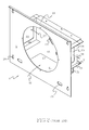
- FIG 2 shows the blower housing 6 according to the prior art, the blower 4 and the Entry ring 5 were removed from Figure 1.
- the entry ring 5 is on the front of the Entry ring support member 3 arranged in the opening 20 while the rest Housing parts (i.e. the top 19, the bottom 21, the back member 18 and the Side elements 22 and 24) are attached to the rear of the entry ring support element 3.
- the inlet air moves in the direction of arrow 16 moves and enters the interior 12 of the housing 6 before it from the fan 4 through the Openings 25 and 23 is pushed out, as shown by arrows 26 and 27.
- the separate side elements 24 and 22 with openings 25 and 23 and the open top 19 can be clearly seen here.
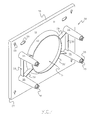
- FIG 3 shows an embodiment of the entry ring according to the invention with an integrated Ring support unit 30.
- the front U of the entry ring support surface 31 can be seen.
- the entry ring support surface 31 has an outer periphery 31 'that defines the boundaries of the unit 30 defined.
- the support surface 31 and the entry ring 32 with its subordinate free-standing edge 32 ' are a single component.
- On the outer periphery of the Entry ring support surface 31 is a raised edge element 33 of surface 31 arranged upstream.
- a variety of standing supports 35 extending from the back (not shown) of the surface 31, form a part with the surface 31.
- In the Surface 31 is also various access and attachment openings 28 and 29 arranged.
- FIG. 4 shows the rear side D of the surface 31 of the unit 30 from FIG. 3 and the rear side of the entry ring 32, which ends with the downstream edge 32 '.
- FIG. 4 shows four standing supports 35 which are integrated in the surface 31. Every prop is oriented downward and has a free end 36 which is a fastener or a Includes receiving element for the fastening means 37. It is shown that that upstanding edge element 33 extends in the entry direction of surface 31, whereas the entry ring 32 extends upwards.
- the spaced apart supports 35 with their opposite free ends 36 define a three-dimensional area in which a blower, e.g. the blower 4 can work.
- This area has the reference symbol 34 in FIG. 4.
- FIG. 4 shows that pairs of supports 35 arranged next to one another with a standing web 38 may be connected to a gain and / or other function for the Total unit can have 30.
- the standing webs 38 can, but do not have to, all connect adjacent pairs of supports 35, but can also only between selected pairs of supports can be arranged, as shown in Figure 4. However, it is also possible to attach a standing web 38 between all supports.
- Individual standing Crosspieces 39 can be between a support and a nearby part of the entry ring 32 be arranged; they can either on all supports 35 or on every second support or in any other desired combination.
- FIG. 5 shows the blower support element 40 with one blower support surface 41 and one upper fastener 42.
- Element 42 extends downward from surface 41.
- An the surface 41 is at an angle to this (approx. 90 ° in FIG. 5) a lower one Closure element 43.
- the blower support element 41 comprises an opening 46 for access on parts of the blower itself and several openings 44 through with the fasteners the free ends 36 of the supports 35 can be connected.
- the element 43 extends in the direction of the front of element 41 and thus under the fan 4.
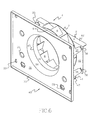
- FIG. 6 shows the fan arrangement 45 according to the invention, which is made up of the two parts of the FIGS. 4 and 5 and composed of the blower 4 after the blower support element 41 attached to the free ends 36 of the supports 35 and the blower 4 in the inner region 34 ( Figure 4), which is defined by the supports 35 and their free ends 36 is.
- the outer edge of the fan joint plate 11 is attached as in FIG. 6, the outer edge 11 '( Figure 1) very close to the downstream entry ring edge 32' ( Figure 4).
- the Distance between the edge 11 '( Figure 1) and the downstream edge 32' ( Figure 4) of the Entry ring 32 is the space 47. Its width should be in the lifetime of the Fan arrangement is approximately 0.15 cm (0.06 inches) plus / minus 0.05 cm (0.02 inches).
- the fan arrangement 45 according to the invention is not a separate one Has side elements such as elements 22 and 24 in Figure 1 (prior art).
- the entry ring with integrated support unit 30 from FIG. 3 can be made of a strong Plastic material such as glass-filled polycarbonate that has great durability, Stability and vibration resistance, exist.
- the other elements of the Fan assembly 45 may be made of the same or different materials. It is can clearly be seen that the two-part fan housing from FIG. 6, that from part 30 composed of Figure 4 and the part 40 of Figure 5, much easier is to be assembled as the blower housing 6 from FIG. 2 consisting of many parts
- Such a fan housing according to the prior art for example, a variety individual welding spots are required in order to hold the blower support element 18 on the blower housing 6 as well as the individual elements of the fan housing 6 to each other according to the prior art Fasten.
- the embodiment 45 of the blower arrangement according to the invention creates improved control of the gap 47 between the entry ring 32 and the steering plate 11 of the blower 4.
- the smaller number of parts and the integrated Construction of the parts used creates an arrangement that is less easily deformable, which increases the probability that the entry ring 32 on the steering plate 11 of the Blower 4 pushes, reduced, even if the gap 47 is very small.
- the construction of the blower assembly 45 has great resilience and stability, so that she runs a much lower risk of warping and a better one at the same time Alignment of the center lines of the inlet ring 32 and fan 4 to each other makes possible.
- the blower arrangement 45 according to the invention does both the assembly and the Installation faster and easier.
Landscapes
- Engineering & Computer Science (AREA)
- Mechanical Engineering (AREA)
- General Engineering & Computer Science (AREA)
- Chemical & Material Sciences (AREA)
- Combustion & Propulsion (AREA)
- Structures Of Non-Positive Displacement Pumps (AREA)
- Accessory Devices And Overall Control Thereof (AREA)
Applications Claiming Priority (2)
| Application Number | Priority Date | Filing Date | Title |
|---|---|---|---|
| US09/699,581 US6503055B1 (en) | 2000-10-30 | 2000-10-30 | Environmental control system blower assembly |
| US699581 | 2003-10-31 |
Publications (2)
| Publication Number | Publication Date |
|---|---|
| EP1202001A2 true EP1202001A2 (fr) | 2002-05-02 |
| EP1202001A3 EP1202001A3 (fr) | 2004-08-04 |
Family
ID=24809967
Family Applications (1)
| Application Number | Title | Priority Date | Filing Date |
|---|---|---|---|
| EP01124334A Withdrawn EP1202001A3 (fr) | 2000-10-30 | 2001-10-22 | Ventilateur soufflant pour un système de conditionnement d'air |
Country Status (5)
| Country | Link |
|---|---|
| US (1) | US6503055B1 (fr) |
| EP (1) | EP1202001A3 (fr) |
| JP (1) | JP4056242B2 (fr) |
| CA (1) | CA2358742C (fr) |
| DE (1) | DE10151986A1 (fr) |
Families Citing this family (14)
| Publication number | Priority date | Publication date | Assignee | Title |
|---|---|---|---|---|
| TWI259049B (en) * | 2003-05-02 | 2006-07-21 | Delta Electronics Inc | Heat-dissipating fan module for electronic apparatus |
| EP1891335B1 (fr) * | 2005-06-06 | 2017-03-29 | Gebr. Becker GmbH | Ventilateur radial |
| US20080199766A1 (en) * | 2007-02-16 | 2008-08-21 | Enermax Technology Corporation | Power supply structure with air guide effect |
| DE202008002356U1 (de) * | 2008-02-19 | 2009-06-25 | Ebm-Papst Mulfingen Gmbh & Co. Kg | Kompaktlüfter |
| JP5727833B2 (ja) * | 2011-03-30 | 2015-06-03 | ミネベア株式会社 | 遠心式ファン |
| US9039362B2 (en) | 2011-03-14 | 2015-05-26 | Minebea Co., Ltd. | Impeller and centrifugal fan using the same |
| JP5832804B2 (ja) | 2011-07-25 | 2015-12-16 | ミネベア株式会社 | 遠心式ファン |
| JP5940266B2 (ja) | 2011-08-29 | 2016-06-29 | ミネベア株式会社 | 遠心式ファン及び遠心式ファンの製造方法 |
| JP6063619B2 (ja) * | 2011-09-29 | 2017-01-18 | ミネベア株式会社 | 遠心式ファン |
| GB2498344B (en) * | 2012-01-10 | 2018-06-06 | Greenwood Air Man Limited | Fan mounting system |
| CN106168390A (zh) * | 2016-08-22 | 2016-11-30 | 珠海格力电器股份有限公司 | 一种圆形壁挂机及采用其的空调 |
| JP6588999B2 (ja) * | 2018-02-16 | 2019-10-09 | ミネベアミツミ株式会社 | 遠心式ファン |
| JP2020122397A (ja) * | 2019-01-29 | 2020-08-13 | 日本電産サンキョー株式会社 | ポンプ装置 |
| CN118595110B (zh) * | 2024-08-06 | 2024-12-03 | 上海浦发热电能源有限公司 | 垃圾吊车控制柜的扫风系统 |
Family Cites Families (14)
| Publication number | Priority date | Publication date | Assignee | Title |
|---|---|---|---|---|
| US2784661A (en) * | 1953-01-26 | 1957-03-12 | Louis J Jenn | Ventilating device |
| US3319546A (en) * | 1962-05-18 | 1967-05-16 | Rca Corp | Electrostatic printing apparatus |
| US4530589A (en) * | 1982-09-21 | 1985-07-23 | Xerox Corporation | Xerographic copying apparatus having means to reduce contamination of optical components |
| US5192973A (en) * | 1987-08-27 | 1993-03-09 | Siemens Aktiengesellschaft | Covering and cleaning device for the optical character generator in an electrophotographic printing device |
| US5086209A (en) * | 1988-02-16 | 1992-02-04 | The Mead Corporation | Hot air apparatus for glossing sheets |
| FR2710700B1 (fr) * | 1993-09-27 | 1995-12-01 | Abb Flakt | Agencement d'un groupe moto-ventilateur monté en caisson. |
| US5409352A (en) * | 1994-04-18 | 1995-04-25 | Lin; Mike | CPU heat dissipating device |
| GB2298520B (en) * | 1995-03-03 | 1999-09-08 | Hong Chen Fu In | Heat sink device for integrated circuit |
| US5677829A (en) * | 1995-06-07 | 1997-10-14 | Thermalloy, Inc. | Fan attachment clip for heat sink |
| US5788566A (en) * | 1996-10-29 | 1998-08-04 | Dell U.S.A., L.P. | Integrated cooling fan and finger guard assembly |
| US5967747A (en) * | 1998-01-20 | 1999-10-19 | Tennant Company | Low noise fan |
| US6017185A (en) * | 1998-08-13 | 2000-01-25 | Chaun-Choung Industrial Corp. | Fan fixing structure of a radiator |
| US6182460B1 (en) * | 1998-08-26 | 2001-02-06 | Carrier Corporation | Window room air conditioner |
| KR100337289B1 (ko) * | 1999-07-28 | 2002-05-17 | 윤종용 | 천정형 에어컨의 벨 마우스장치 |
-
2000
- 2000-10-30 US US09/699,581 patent/US6503055B1/en not_active Expired - Fee Related
-
2001
- 2001-10-12 CA CA002358742A patent/CA2358742C/fr not_active Expired - Fee Related
- 2001-10-22 DE DE10151986A patent/DE10151986A1/de not_active Withdrawn
- 2001-10-22 EP EP01124334A patent/EP1202001A3/fr not_active Withdrawn
- 2001-10-29 JP JP2001330375A patent/JP4056242B2/ja not_active Expired - Fee Related
Also Published As
| Publication number | Publication date |
|---|---|
| CA2358742A1 (fr) | 2002-04-30 |
| EP1202001A3 (fr) | 2004-08-04 |
| US6503055B1 (en) | 2003-01-07 |
| JP2002195197A (ja) | 2002-07-10 |
| CA2358742C (fr) | 2006-01-17 |
| DE10151986A1 (de) | 2002-05-08 |
| JP4056242B2 (ja) | 2008-03-05 |
Similar Documents
| Publication | Publication Date | Title |
|---|---|---|
| DE69029277T2 (de) | Aerodynamischer Lufteinlass einer Tunnelbelüftungseinrichtung | |
| DE10151986A1 (de) | Gebläseanordnung für ein Klimatisierungssystem | |
| DE2840837C2 (de) | Ölabscheider zur Entlüftung des Kurbelraumes von Verbrennungskraftmaschinen | |
| EP0942638A2 (fr) | Boítier ventilé | |
| EP0027984B1 (fr) | Réacteur à eau bouillante | |
| DE602004000084T2 (de) | Baugruppe zur installation von leistungselektronikmodulen und installationsverfahren | |
| EP2286153B1 (fr) | Déflecteur d'air | |
| DE69905002T2 (de) | Ausstrahlungsvorrichtung | |
| DE69108015T2 (de) | Tragbares hochdruckreinigungsgerät. | |
| DE112013007680B4 (de) | System zur Befestigung eines inneren Luftablenkblechs an einer Luftablenkkappe für elektrische Maschinen | |
| EP0940632A1 (fr) | Hotte d'aspiration | |
| DE1154252B (de) | Abschirmung von Raumoeffnungen durch einen Luftschleier | |
| EP2243533A1 (fr) | Pare-goutte | |
| DE29822723U1 (de) | Kühlvorrichtung für ein Festplattenlaufwerk | |
| EP0634207A1 (fr) | Installation combinée de mélange et de changement de direction | |
| EP2982014B1 (fr) | Réalisation d'un type de protection pour appareils électriques et électroniques, en particulier pour armoires de distribution | |
| DE69834669T2 (de) | Verbrennungsgerät | |
| EP2613096B1 (fr) | Cheminée de ventilation domestique avec quatre plaques de filtre parallèles | |
| DE19715516C1 (de) | Lüftungsgitter | |
| DE9301943U1 (de) | Variable Staubabsaugung | |
| DE9001929U1 (de) | Lüftereinschub zum Abführen der Verlustwärme von elektrischen Bauteilen und Baugruppen | |
| DE68920988T2 (de) | Schutzmittel für Ein- und Auslass der Ventilationsluft in elektrischen Drehmaschinen. | |
| DE20013450U1 (de) | Filterlüfter | |
| EP0043504A1 (fr) | Boîte à monter dans un mur extérieur pour les conduits de l'air de combustion et du gaz d'échappement d'un appareil fonctionnant avec un système à brûleur | |
| DE8714894U1 (de) | Lüftereinsatz für die Kühlung elektrischer bzw. elektronischer Baugruppen |
Legal Events
| Date | Code | Title | Description |
|---|---|---|---|
| PUAI | Public reference made under article 153(3) epc to a published international application that has entered the european phase |
Free format text: ORIGINAL CODE: 0009012 |
|
| AK | Designated contracting states |
Kind code of ref document: A2 Designated state(s): AT BE CH CY DE DK ES FI FR GB GR IE IT LI LU MC NL PT SE TR |
|
| AX | Request for extension of the european patent |
Free format text: AL;LT;LV;MK;RO;SI |
|
| PUAL | Search report despatched |
Free format text: ORIGINAL CODE: 0009013 |
|
| AK | Designated contracting states |
Kind code of ref document: A3 Designated state(s): AT BE CH CY DE DK ES FI FR GB GR IE IT LI LU MC NL PT SE TR |
|
| AX | Request for extension of the european patent |
Extension state: AL LT LV MK RO SI |
|
| RIC1 | Information provided on ipc code assigned before grant |
Ipc: 7F 04D 29/42 B Ipc: 7F 24F 7/007 A |
|
| RAP1 | Party data changed (applicant data changed or rights of an application transferred) |
Owner name: EASTMAN KODAK COMPANY |
|
| 17P | Request for examination filed |
Effective date: 20041221 |
|
| AKX | Designation fees paid |
Designated state(s): DE |
|
| 17Q | First examination report despatched |
Effective date: 20061013 |
|
| STAA | Information on the status of an ep patent application or granted ep patent |
Free format text: STATUS: THE APPLICATION IS DEEMED TO BE WITHDRAWN |
|
| 18D | Application deemed to be withdrawn |
Effective date: 20070224 |