EP1202010A1 - Equipement thermodynamique multifonctions - Google Patents
Equipement thermodynamique multifonctions Download PDFInfo
- Publication number
- EP1202010A1 EP1202010A1 EP00940110A EP00940110A EP1202010A1 EP 1202010 A1 EP1202010 A1 EP 1202010A1 EP 00940110 A EP00940110 A EP 00940110A EP 00940110 A EP00940110 A EP 00940110A EP 1202010 A1 EP1202010 A1 EP 1202010A1
- Authority
- EP
- European Patent Office
- Prior art keywords
- water heater
- energy
- compressor
- water
- multifunctional
- Prior art date
- Legal status (The legal status is an assumption and is not a legal conclusion. Google has not performed a legal analysis and makes no representation as to the accuracy of the status listed.)
- Withdrawn
Links
Images

Classifications
-
- F—MECHANICAL ENGINEERING; LIGHTING; HEATING; WEAPONS; BLASTING
- F24—HEATING; RANGES; VENTILATING
- F24D—DOMESTIC- OR SPACE-HEATING SYSTEMS, e.g. CENTRAL HEATING SYSTEMS; DOMESTIC HOT-WATER SUPPLY SYSTEMS; ELEMENTS OR COMPONENTS THEREFOR
- F24D15/00—Other domestic- or space-heating systems
- F24D15/04—Other domestic- or space-heating systems using heat pumps
-
- F—MECHANICAL ENGINEERING; LIGHTING; HEATING; WEAPONS; BLASTING
- F24—HEATING; RANGES; VENTILATING
- F24F—AIR-CONDITIONING; AIR-HUMIDIFICATION; VENTILATION; USE OF AIR CURRENTS FOR SCREENING
- F24F5/00—Air-conditioning systems or apparatus not covered by F24F1/00 or F24F3/00, e.g. using solar heat or combined with household units such as an oven or water heater
- F24F5/0096—Air-conditioning systems or apparatus not covered by F24F1/00 or F24F3/00, e.g. using solar heat or combined with household units such as an oven or water heater combined with domestic apparatus
-
- F—MECHANICAL ENGINEERING; LIGHTING; HEATING; WEAPONS; BLASTING
- F25—REFRIGERATION OR COOLING; COMBINED HEATING AND REFRIGERATION SYSTEMS; HEAT PUMP SYSTEMS; MANUFACTURE OR STORAGE OF ICE; LIQUEFACTION SOLIDIFICATION OF GASES
- F25B—REFRIGERATION MACHINES, PLANTS OR SYSTEMS; COMBINED HEATING AND REFRIGERATION SYSTEMS; HEAT PUMP SYSTEMS
- F25B13/00—Compression machines, plants or systems, with reversible cycle
-
- F—MECHANICAL ENGINEERING; LIGHTING; HEATING; WEAPONS; BLASTING
- F24—HEATING; RANGES; VENTILATING
- F24D—DOMESTIC- OR SPACE-HEATING SYSTEMS, e.g. CENTRAL HEATING SYSTEMS; DOMESTIC HOT-WATER SUPPLY SYSTEMS; ELEMENTS OR COMPONENTS THEREFOR
- F24D3/00—Hot-water central heating systems
- F24D3/08—Hot-water central heating systems in combination with systems for domestic hot-water supply
-
- F—MECHANICAL ENGINEERING; LIGHTING; HEATING; WEAPONS; BLASTING
- F25—REFRIGERATION OR COOLING; COMBINED HEATING AND REFRIGERATION SYSTEMS; HEAT PUMP SYSTEMS; MANUFACTURE OR STORAGE OF ICE; LIQUEFACTION SOLIDIFICATION OF GASES
- F25B—REFRIGERATION MACHINES, PLANTS OR SYSTEMS; COMBINED HEATING AND REFRIGERATION SYSTEMS; HEAT PUMP SYSTEMS
- F25B2313/00—Compression machines, plants or systems with reversible cycle not otherwise provided for
- F25B2313/002—Compression machines, plants or systems with reversible cycle not otherwise provided for geothermal
-
- F—MECHANICAL ENGINEERING; LIGHTING; HEATING; WEAPONS; BLASTING
- F25—REFRIGERATION OR COOLING; COMBINED HEATING AND REFRIGERATION SYSTEMS; HEAT PUMP SYSTEMS; MANUFACTURE OR STORAGE OF ICE; LIQUEFACTION SOLIDIFICATION OF GASES
- F25B—REFRIGERATION MACHINES, PLANTS OR SYSTEMS; COMBINED HEATING AND REFRIGERATION SYSTEMS; HEAT PUMP SYSTEMS
- F25B2313/00—Compression machines, plants or systems with reversible cycle not otherwise provided for
- F25B2313/004—Outdoor unit with water as a heat sink or heat source
-
- F—MECHANICAL ENGINEERING; LIGHTING; HEATING; WEAPONS; BLASTING
- F25—REFRIGERATION OR COOLING; COMBINED HEATING AND REFRIGERATION SYSTEMS; HEAT PUMP SYSTEMS; MANUFACTURE OR STORAGE OF ICE; LIQUEFACTION SOLIDIFICATION OF GASES
- F25B—REFRIGERATION MACHINES, PLANTS OR SYSTEMS; COMBINED HEATING AND REFRIGERATION SYSTEMS; HEAT PUMP SYSTEMS
- F25B2313/00—Compression machines, plants or systems with reversible cycle not otherwise provided for
- F25B2313/023—Compression machines, plants or systems with reversible cycle not otherwise provided for using multiple indoor units
-
- F—MECHANICAL ENGINEERING; LIGHTING; HEATING; WEAPONS; BLASTING
- F25—REFRIGERATION OR COOLING; COMBINED HEATING AND REFRIGERATION SYSTEMS; HEAT PUMP SYSTEMS; MANUFACTURE OR STORAGE OF ICE; LIQUEFACTION SOLIDIFICATION OF GASES
- F25B—REFRIGERATION MACHINES, PLANTS OR SYSTEMS; COMBINED HEATING AND REFRIGERATION SYSTEMS; HEAT PUMP SYSTEMS
- F25B2313/00—Compression machines, plants or systems with reversible cycle not otherwise provided for
- F25B2313/025—Compression machines, plants or systems with reversible cycle not otherwise provided for using multiple outdoor units
-
- F—MECHANICAL ENGINEERING; LIGHTING; HEATING; WEAPONS; BLASTING
- F25—REFRIGERATION OR COOLING; COMBINED HEATING AND REFRIGERATION SYSTEMS; HEAT PUMP SYSTEMS; MANUFACTURE OR STORAGE OF ICE; LIQUEFACTION SOLIDIFICATION OF GASES
- F25B—REFRIGERATION MACHINES, PLANTS OR SYSTEMS; COMBINED HEATING AND REFRIGERATION SYSTEMS; HEAT PUMP SYSTEMS
- F25B30/00—Heat pumps
- F25B30/06—Heat pumps characterised by the source of low potential heat
-
- Y—GENERAL TAGGING OF NEW TECHNOLOGICAL DEVELOPMENTS; GENERAL TAGGING OF CROSS-SECTIONAL TECHNOLOGIES SPANNING OVER SEVERAL SECTIONS OF THE IPC; TECHNICAL SUBJECTS COVERED BY FORMER USPC CROSS-REFERENCE ART COLLECTIONS [XRACs] AND DIGESTS
- Y02—TECHNOLOGIES OR APPLICATIONS FOR MITIGATION OR ADAPTATION AGAINST CLIMATE CHANGE
- Y02B—CLIMATE CHANGE MITIGATION TECHNOLOGIES RELATED TO BUILDINGS, e.g. HOUSING, HOUSE APPLIANCES OR RELATED END-USER APPLICATIONS
- Y02B30/00—Energy efficient heating, ventilation or air conditioning [HVAC]
- Y02B30/12—Hot water central heating systems using heat pumps
Definitions
- the present invention relates to a multifunctional thermal installation used to improve living conditions.
- This household multifunctional thermal installation is a multifunctional integrated system of air conditioning, heating, living hot water and energy storage.
- the object of the present invention is to provide a multifunctional thermal installation used to improve living conditions on the basis of the concept of sustainable development and ecological equilibrium. If the separate installations are made into an integrated system called multifunctional system, only a little amount of non-renewable energy resource is used can most of energy resources be replaced by the renewable energy resources collected from the system, so that the pollution that is brought by the consumption of energy resources can be reduced efficiently. Meanwhile, large amount of non-renewable energy resources can be saved and covered.
- a multifunctional thermal installation including a compressor, an evaporator, a condenser and an expansion valve, of which the evaporator and the condenser at least comprise of a group of heat exchangers, wherein a switch valve is provided at the end of the outlet of the compressor; at least one group of the heat exchangers are disposed within the water heater, while another group of the heat exchangers together with their associated fans are disposed inside the room; the inlet of the water heater is connected to an underground well.
- the switch valve at the outlet of the compressor of the present invention is connected to the heat exchanger inside the room to form a heat supply circulating device, however, the switch valve can also turn to the heat exchanger disposed in the water heater to form a refrigerating circulating device.
- Said water heater can be an enclosed water tank with a hot water outlet and said compressor can be disposed inside the water heater.
- the water inlet of the water heater can be connected to an underground well through a pump.
- the operational principle of the mullifunctional thermal installation is as follows:
- the multifunctional cold/hot air blower has also a fan and an evaporating/condensing heat exchanger as ordinary cold/hot air blowers do, and the structure of multifunctional water heater is substantially same to those of the ordinary ones.
- the compressor condensing process is used in the refrigeration and the reverse cycle of the said process is used in the heat supply of the multifunctional cold/hot air blower and no more description on the operational principle of the heat supply shall be made herein.
- the combined installation is a multifunctional integration of a multifunctional blower, a compressor and a multifunctional water heater.
- the multifunctional integration only consumes 10-20% of the absolute value of the total non-renewable energy resources of the system and other energy resources it needs come from alternate energy resources. This integrated system is called "multifunctional system".
- the condensing temperature of 40°C and evaporating temperature of 5°C is used in conventional air-conditioners with R22 as work medium, while the evaporating temperature used in the combined installation is more than 12°C and the condensing temperature is 20°C or even lower.
- the LGp-H circulation figure is attached for reference.
- the cost/performance ratio of the multifunctional installation is much higher than that of the conventional top-grade household appliances, it will be more advantageous if the multifunctional installations are promoted in developing countries using the one-step model, which avoids taking the road back using the development model of the developed countries. Since nearly 100 million sets of household appliances are needed in developing countries every year, the promotion of the multifunctional installation in these countries constitutes a large-scale system project of recovery of global warming. If conventional household appliances are still used, the greenhouse gases shall increase at an order of magnitude of 100 million tons per year.
- the present invention is a multifunctional installation mainly including a compressor 1, an evaporator 3 or 6, a condenser 6 or 3 and an expansion valve 5, wherein the evaporator and the condenser both include a group of heat exchangers 31 or 61 and a fan.
- an expansion valve 2 At the outlet of the compressor 1 of the present invention there is provided an expansion valve 2 of which different changes can result in refrigerating system and heating system; wherein one group of the heat exchangers 61 are disposed in a water heater 7 and the other group 31 together with their corresponding fans are disposed inside the room; the water inlet of the water heater 7 is connected to a well.
- the operational principle of the present invention is very simple, when refrigeration is needed, the water heater collects 12-16°C water from the underground well, the switch valve at the end of the outlet of the compressor 1 is connected to the heat exchanger 61 which is inside the water heater, the cryogen is changed into high-temperature saturated gas of more than 65°C after compressed by the compressor 1, then its temperature is lowered by the heat exchanger 61 after heat exchange with the low-temperature water in the water heater 7, and then the condensed cryogen enters the heat exchanger 31 inside the room to be evaporated and absorbs large amount of heat after being expanded by the expansion valve 5, thus the refrigeration process is finished.
- the heat exchanger 61 functions as a condenser and the heat exchanger 31 functions as an evaporator, so a cold air blower is formed.
- the low-temperature water in the water heater 7 shall be changed into 62°C hot water for use directly. Therefore, refrigerating energy of the cold air blower comes from the water heater 7 and the thermal energy of the water heater 7 comes from the cold air blower, the residual thermal energy of the water heater 7 can be stored in the underground well for use as the primary thermal energy for heating in winter.
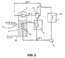
- the other work condition of the present invention is heating process as shown in Fig 2.
- the water heater 7 collects 16-30°C warm water that is stored in summer from the underground well, the switch valve at the end of the outlet of the compressor 1 is connected to the heat exchanger 31 which is inside the water heater, the cryogen is changed into high-temperature gas work medium of more than 55°C after compressed by the compressor 1, and then condensed by the heat exchanger 3 1 and gives out heat.
- the condensed cryogen enters the heat exchanger 61 inside the room to be evaporated and absorbs heat after being expanded by the expansion valve 5.
- the heat exchanger 31 functions as a condenser and the heat exchanger 61 functions as an evaporator and thus a heating device is formed.
- the heating energy of the hot air blower mainly comes from the energy stored in the underground well in those seasons that need not heating, and the water from which the thermal energy has been absorbed by the hot air blower shall be stored in the underground well for use as the refrigerating energy in summer.
- the combined installation of the present invention is an integrated accrete body of which the cold/hot air blower and the multifunctional water heater constitute a common thermodynamic circulation after compensating each other, so the installation is compact in structure. Since the thermodynamic processes of two functions are combined into one in it, the work condition of the combined installation is much lower than that of conventional air-conditioners, i.e. the seasonal energy-efficiency ratio (SEER) can reach 10 or greater that is more than two times of that of conventional air-conditioners.
- SEER seasonal energy-efficiency ratio
- the water heater 7 is an enclosed water container which is provided with a water inlet 71 that is connected to an underground well, from the well 8-16°C low-temperature water is pumped into the enclosed water heater 7 by the pump 8; the compressor 1 can also be disposed in the water heater 7, the switch valve 2 at the end of the outlet of the compressor 1 is connected to the heat exchanger 61 which is inside the water heater 7, after being compressed, the cryogen is changed into gas work medium with the high temperature of 65°C, and then the high-temperature gas work medium can lower the temperature efficiently after heat exchange with the low-temperature water in the water heater 7 through heat exchanger 61.
- the temperature of the cryogen of which the temperature has been lowered to -4°C shall be generally lowered to -15°C after expanded through the expansion valve 5, and then it enters the heat exchanger 31 which is inside the room to be evaporated and absorbs the heat in the room to finish the refrigerating process.
- the heat exchanger 61 in the hot water heater 7 functions as a condenser and the heat exchanger 31 in the room functions as an evaporator.
- the water of 62°C is obtained and flows out for use through the hot water outlet 72 disposed on the water heater 7.
- the residual hot water can be stored in the underground well for use as the primary thermal energy for heating in winter.
- Fig.2 shows the second embodiment of the present invention.
- the water heater 7 is an enclosed water container which is provided with a water inlet 71 connected to an underground well, in the underground well there is warm water of 16-30°C that was stored in summer, and the warm water is pumped by the pump 8 into the water heater 7;
- the compressor 1 is disposed inside the water heater 7;
- the switch valve 2 at the end of the output of the compressor 1 is connected to the heat exchanger 31 in the room;
- the cryogen is changed into gas work medium of 55°C after being compressed and then exchanges heat with the low-temperature air in the room through the heat exchanger 31, thus a hot air blower is formed.
- the temperature of the air outlet of the hot air blower can reach 55°C, so the function for heating the room is realized.
- the cryogen of which the temperature has been lowered shall enter the heat exchanger 61 for evaporating and absorbing after it is lowered further to - 15°C by being expanded in expansion valve 5.
- the water in the water heater is changed into low-temperature water of 1-2°C and then stored in the underground well for use as the primary refrigerating energy in summer.
- the heat exchanger 61 inside the water heater 7 functions as an evaporator and the heat exchanger in the room functions as a condenser.
Landscapes
- Engineering & Computer Science (AREA)
- Mechanical Engineering (AREA)
- General Engineering & Computer Science (AREA)
- Physics & Mathematics (AREA)
- Thermal Sciences (AREA)
- Chemical & Material Sciences (AREA)
- Combustion & Propulsion (AREA)
- Life Sciences & Earth Sciences (AREA)
- Sustainable Development (AREA)
- Heat-Pump Type And Storage Water Heaters (AREA)
- Steam Or Hot-Water Central Heating Systems (AREA)
- Other Air-Conditioning Systems (AREA)
Applications Claiming Priority (3)
| Application Number | Priority Date | Filing Date | Title |
|---|---|---|---|
| CNB991096487A CN1156659C (zh) | 1999-07-02 | 1999-07-02 | 泛能热力设施 |
| CN99109648 | 1999-07-02 | ||
| PCT/CN2000/000172 WO2001002783A1 (fr) | 1999-07-02 | 2000-06-23 | Equipement thermodynamique multifonctions |
Publications (2)
| Publication Number | Publication Date |
|---|---|
| EP1202010A1 true EP1202010A1 (fr) | 2002-05-02 |
| EP1202010A4 EP1202010A4 (fr) | 2009-08-26 |
Family
ID=5274049
Family Applications (1)
| Application Number | Title | Priority Date | Filing Date |
|---|---|---|---|
| EP00940110A Withdrawn EP1202010A4 (fr) | 1999-07-02 | 2000-06-23 | Equipement thermodynamique multifonctions |
Country Status (6)
| Country | Link |
|---|---|
| US (2) | US20020100576A1 (fr) |
| EP (1) | EP1202010A4 (fr) |
| JP (1) | JP2003503673A (fr) |
| CN (1) | CN1156659C (fr) |
| AU (1) | AU5518600A (fr) |
| WO (1) | WO2001002783A1 (fr) |
Families Citing this family (15)
| Publication number | Priority date | Publication date | Assignee | Title |
|---|---|---|---|---|
| US8633604B2 (en) * | 2007-02-19 | 2014-01-21 | Michael Miller | Engine |
| DE102008016663A1 (de) | 2008-04-01 | 2009-10-08 | Efficient Energy Gmbh | Verflüssiger für eine Wärmepumpe und Wärmepumpe |
| WO2012125386A1 (fr) * | 2011-03-11 | 2012-09-20 | Carrier Corporation | Unité de toit |
| CN102221270B (zh) * | 2011-07-15 | 2012-09-05 | 中山市爱美泰电器有限公司 | 一种热泵机组与太阳能联动的供冷暖和生活热水装置 |
| US10119738B2 (en) | 2014-09-26 | 2018-11-06 | Waterfurnace International Inc. | Air conditioning system with vapor injection compressor |
| US10100683B2 (en) | 2014-12-24 | 2018-10-16 | Michael Miller | Compressed gas engine |
| US9765758B2 (en) | 2014-12-24 | 2017-09-19 | Michael Miller | Compressed gas engine |
| US10871314B2 (en) | 2016-07-08 | 2020-12-22 | Climate Master, Inc. | Heat pump and water heater |
| US10866002B2 (en) | 2016-11-09 | 2020-12-15 | Climate Master, Inc. | Hybrid heat pump with improved dehumidification |
| CN106556179B (zh) * | 2016-11-24 | 2020-06-16 | 青岛海尔空调电子有限公司 | 一种换热器以及应用该换热器的空调系统 |
| US10914478B2 (en) | 2018-03-15 | 2021-02-09 | Michael Miller | Portable energy generation and humidity control system |
| US11592215B2 (en) | 2018-08-29 | 2023-02-28 | Waterfurnace International, Inc. | Integrated demand water heating using a capacity modulated heat pump with desuperheater |
| CA3081986A1 (fr) | 2019-07-15 | 2021-01-15 | Climate Master, Inc. | Systeme de conditionnement d`air a regulation de puissance et production d`eau chaude controlee |
| US12181189B2 (en) | 2021-11-10 | 2024-12-31 | Climate Master, Inc. | Ceiling-mountable heat pump system |
| CN114659088B (zh) * | 2022-03-14 | 2024-02-06 | 中国恩菲工程技术有限公司 | 乏汽收能系统和冷却水流量确定方法 |
Family Cites Families (9)
| Publication number | Priority date | Publication date | Assignee | Title |
|---|---|---|---|---|
| US4402190A (en) * | 1982-05-11 | 1983-09-06 | Reid Samuel I | Apparatus and method for heating and chilling concrete batch water |
| JPS5924156A (ja) * | 1982-07-31 | 1984-02-07 | サンデン株式会社 | ヒ−トポンプ式冷暖房湯沸かし装置 |
| KR900000809B1 (ko) * | 1984-02-09 | 1990-02-17 | 미쓰비시전기 주식회사 | 냉난방 · 급탕용(給湯用) 히트펌프장치 |
| WO1988007162A1 (fr) * | 1985-01-28 | 1988-09-22 | Martin James B Jr | Systeme servant a chauffer et a refroidir des liquides |
| JPH0329904U (fr) * | 1989-07-29 | 1991-03-25 | ||
| CN2072256U (zh) * | 1989-08-10 | 1991-02-27 | 鲁德孚 | 立体几何学习工具盒 |
| CN1072256A (zh) * | 1991-11-07 | 1993-05-19 | 刘云 | 节能地温空调系统 |
| CN1072010A (zh) * | 1992-10-13 | 1993-05-12 | 上海桑菱环境能源研究所 | 一种热泵供热供冷系统 |
| US5802864A (en) * | 1997-04-01 | 1998-09-08 | Peregrine Industries, Inc. | Heat transfer system |
-
1999
- 1999-07-02 CN CNB991096487A patent/CN1156659C/zh not_active Expired - Fee Related
-
2000
- 2000-06-23 EP EP00940110A patent/EP1202010A4/fr not_active Withdrawn
- 2000-06-23 JP JP2001507986A patent/JP2003503673A/ja active Pending
- 2000-06-23 AU AU55186/00A patent/AU5518600A/en not_active Abandoned
- 2000-06-23 WO PCT/CN2000/000172 patent/WO2001002783A1/fr not_active Ceased
-
2002
- 2002-01-02 US US10/038,034 patent/US20020100576A1/en not_active Abandoned
-
2004
- 2004-01-02 US US10/751,083 patent/US20040140082A1/en not_active Abandoned
Also Published As
| Publication number | Publication date |
|---|---|
| CN1156659C (zh) | 2004-07-07 |
| US20020100576A1 (en) | 2002-08-01 |
| WO2001002783A1 (fr) | 2001-01-11 |
| EP1202010A4 (fr) | 2009-08-26 |
| AU5518600A (en) | 2001-01-22 |
| CN1281131A (zh) | 2001-01-24 |
| US20040140082A1 (en) | 2004-07-22 |
| JP2003503673A (ja) | 2003-01-28 |
Similar Documents
| Publication | Publication Date | Title |
|---|---|---|
| LU102468B1 (en) | Total heat recovery type integrated gas heat pump heat supply unit and application thereof | |
| EP1202010A1 (fr) | Equipement thermodynamique multifonctions | |
| CN103292393B (zh) | 太阳能光伏光热复合式空调器 | |
| Shao et al. | A new inverter heat pump operated all year round with domestic hot water | |
| CN201440013U (zh) | 一种空调机组 | |
| CN101165435B (zh) | 双效压缩式冷热水节能机组 | |
| Alelyani et al. | Assessment of a novel heat-driven cycle to produce shaft power and refrigeration | |
| CN102410668A (zh) | 相变蓄能式太阳能复合能源冷、暖、热水三联供系统 | |
| CN101178230A (zh) | 多功能太阳能空调 | |
| CN202350383U (zh) | 相变蓄能式太阳能复合能源冷、暖、热水三联供系统 | |
| CN105258379A (zh) | 热泵型太阳能蒸发式冷凝空调机组 | |
| CN201363899Y (zh) | 带应急备用电源的空气源热泵热水装置 | |
| CN2394139Y (zh) | 太阳能、地热冷热水机组 | |
| CN217464714U (zh) | 太阳能光伏光电集热一体化空气源热泵空调水循环系统 | |
| CN201081456Y (zh) | 一种双冷凝器的高效节能空调热水器系统 | |
| CN2470714Y (zh) | 一种双级热泵采暖供热装置 | |
| KR20130112394A (ko) | 고효율 하이브리드식 히트펌프장치 | |
| CN207350989U (zh) | 新型多能源综合利用空调热水热回收一体机 | |
| CN2380846Y (zh) | 泛能热力装置 | |
| CN205664584U (zh) | 冷热节能回收系统 | |
| KR200431243Y1 (ko) | 냉난방 시스템 | |
| CN113899110B (zh) | 一种具有中间过程的吸收式冷热联供系统 | |
| CN107687719A (zh) | 新型多能源综合利用空调热水热回收一体机 | |
| CN201637194U (zh) | 多功能热回收装置 | |
| CN202267159U (zh) | 一种空调装置 |
Legal Events
| Date | Code | Title | Description |
|---|---|---|---|
| PUAI | Public reference made under article 153(3) epc to a published international application that has entered the european phase |
Free format text: ORIGINAL CODE: 0009012 |
|
| 17P | Request for examination filed |
Effective date: 20020109 |
|
| AK | Designated contracting states |
Kind code of ref document: A1 Designated state(s): AT BE CH CY DE DK ES FI FR GB GR IE IT LI LU MC NL PT SE |
|
| AX | Request for extension of the european patent |
Free format text: AL;LT;LV;MK;RO;SI |
|
| A4 | Supplementary search report drawn up and despatched |
Effective date: 20090724 |
|
| 17Q | First examination report despatched |
Effective date: 20091222 |
|
| STAA | Information on the status of an ep patent application or granted ep patent |
Free format text: STATUS: THE APPLICATION IS DEEMED TO BE WITHDRAWN |
|
| 18D | Application deemed to be withdrawn |
Effective date: 20100105 |