EP1202011B1 - Kühlschrank und Tragböden hierfür - Google Patents
Kühlschrank und Tragböden hierfür Download PDFInfo
- Publication number
- EP1202011B1 EP1202011B1 EP01124529A EP01124529A EP1202011B1 EP 1202011 B1 EP1202011 B1 EP 1202011B1 EP 01124529 A EP01124529 A EP 01124529A EP 01124529 A EP01124529 A EP 01124529A EP 1202011 B1 EP1202011 B1 EP 1202011B1
- Authority
- EP
- European Patent Office
- Prior art keywords
- shelf
- refrigerator
- refrigerator according
- support
- stop
- Prior art date
- Legal status (The legal status is an assumption and is not a legal conclusion. Google has not performed a legal analysis and makes no representation as to the accuracy of the status listed.)
- Expired - Lifetime
Links
Images


Classifications
-
- F—MECHANICAL ENGINEERING; LIGHTING; HEATING; WEAPONS; BLASTING
- F25—REFRIGERATION OR COOLING; COMBINED HEATING AND REFRIGERATION SYSTEMS; HEAT PUMP SYSTEMS; MANUFACTURE OR STORAGE OF ICE; LIQUEFACTION SOLIDIFICATION OF GASES
- F25D—REFRIGERATORS; COLD ROOMS; ICE-BOXES; COOLING OR FREEZING APPARATUS NOT OTHERWISE PROVIDED FOR
- F25D25/00—Charging, supporting, and discharging the articles to be cooled
- F25D25/02—Charging, supporting, and discharging the articles to be cooled by shelves
- F25D25/024—Slidable shelves
-
- F—MECHANICAL ENGINEERING; LIGHTING; HEATING; WEAPONS; BLASTING
- F25—REFRIGERATION OR COOLING; COMBINED HEATING AND REFRIGERATION SYSTEMS; HEAT PUMP SYSTEMS; MANUFACTURE OR STORAGE OF ICE; LIQUEFACTION SOLIDIFICATION OF GASES
- F25D—REFRIGERATORS; COLD ROOMS; ICE-BOXES; COOLING OR FREEZING APPARATUS NOT OTHERWISE PROVIDED FOR
- F25D2325/00—Charging, supporting or discharging the articles to be cooled, not provided for in other groups of this subclass
- F25D2325/022—Shelves made of glass or ceramic
-
- F—MECHANICAL ENGINEERING; LIGHTING; HEATING; WEAPONS; BLASTING
- F25—REFRIGERATION OR COOLING; COMBINED HEATING AND REFRIGERATION SYSTEMS; HEAT PUMP SYSTEMS; MANUFACTURE OR STORAGE OF ICE; LIQUEFACTION SOLIDIFICATION OF GASES
- F25D—REFRIGERATORS; COLD ROOMS; ICE-BOXES; COOLING OR FREEZING APPARATUS NOT OTHERWISE PROVIDED FOR
- F25D2500/00—Problems to be solved
- F25D2500/02—Geometry problems
Definitions
- the present invention relates to a refrigerator with a support base and a support base bracket, wherein the support floor a flat plate body and an attached stop for securing the tray against slipping out of a support base bracket of the cooling unit.
- a refrigerator according to the preamble of claim 1 is e.g. known from US 5,788,094.
- trays for refrigerators glass plates which at their rear and front edges are bordered with plastic injection-retaining strips.
- the retaining strips can the glass plates at its front end in the corner areas enclose so far that in each case a stop can be attached, the can engage in corresponding recesses in the refrigerator inner wall, to prevent the tray unintentionally from the support base bracket from slipping out.
- the present invention is therefore based on the object, an improved Refrigerator or an improved support floor of the type mentioned avoid the disadvantages of the prior art and the latter in an advantageous manner Continue education. In particular, an improved backup of the trays be achieved in the refrigerator.
- the invention proposes a cooling device according to claim 1 ago.
- the stopper is thus separate and spaced from the edge profile at the front formed the support plate.
- the stop can be positioned independently of the front edge profile be used for any installation situation.
- the separation of the Attack of the front edge profile also allows the latter independently to make of the stop function.
- as an edge profile Metal profile can be used.
- the stop does not need to be molded to the edge profile to be.
- an elastic buffer is preferably provided, which is the supporting floor against slipping out of the corresponding support base bracket of the refrigerator guaranteed.
- Such an elastic buffer body prevents damage to the Supporting floor support, which is usually in the form of support ribs on the inner container wall the cooling device is formed.
- the stop outside the contact area of the Carrying floor arranged.
- the support base does not lie with the stop on the cooling unit side Tragêthalterung on, so that the unwanted crackling noises can be avoided. It is intended that it be immediate the plate body of the supporting floor is that on the cooling unit side support floor bracket rests.
- the plate body is made of glass, creating a Noise when lying on the support bracket completely avoided is.
- the material pairing glass and polystyrene, from which usually the container inner wall exists, is no problem in terms of noise.
- the support floor comprises two elastic buffers on are arranged opposite sides of the glass plate.
- the Stop with a specially provided projection on the inside of the container interact to hold the support plate.
- the Stopper designed such that it with the support base bracket of the cooling device interacts.
- the support floor bracket a recess into which engages the stop of the support floor.
- the support floor bracket has projecting on the inner walls of the refrigerator Auflagerippen, of which at least one an interruption for the stop has.
- the stopper can have different shapes and geometries. According to one advantageous embodiment of the invention, it is as a button-shaped projection in particular provided on the underside of the support floor.
- the elastic buffer can made of rubber or a rubber-elastic plastic. He can also go out consist of another suitable elastic plastic.
- the stopper is formed separately from the plate body and firmly connected to this.
- the connection between the stop and the plate body is cohesively formed, in particular, the stopper can be glued to the plate body be.
- the stop is preferred adapted to the Tragêtkorpus.
- the stopper can be transparent be educated.
- the stop In contrast to conventional solutions with plastic injection-retaining strips, is the stop separately and spaced from a profiled strip formed, the one Edge of the supporting body.
- edging Profile strip provided a metal strip
- the two a Tragplattenkante has overarching legs, the free ends are repelled and parallel Support legs form on opposite surfaces of the tray rest.
- the profile strip thus has a total of C-shaped profile with inside, i. towards the concave side turned back leg ends. hereby Significant benefits are achieved regardless of the formation of the attack.
- the formation of the profile strip made of metal causes a particularly stable Protection of the supporting floor edge against impact.
- the handled Support legs a double suspension of the profile strip in the smallest space.
- the overlapping legs can spring apart and together,
- the support legs clamp elastically the opposite Surfaces of the supporting floor between them.
- the connection between the profile strip and the tray body may be formed free of adhesive and alone be effected by the clamping. As a result, the mounting of the trays considerably relieved.
- a particularly advantageous embodiment of the invention is that the profile strip a curved in cross-section, in particular circular arc-shaped Leistenkorpus possesses, to which the two struck back legs connect.
- the outwardly projecting profile body is free of formed sharp edges, where users of the refrigerator encounter or food could be damaged during loading and unloading.
- the profile strips are outside arranged the support areas of the support floor. You can talk about the entire edge extend into the side region of the supporting body, with the this rests on the support bracket.
- the support floor bracket is listening expediently before reaching the corresponding profile strip or stands the Tragêtkorpus over the support base bracket over, so that the Profile strip does not rest on the support base holder.
- the profile strip itself is preferably made of a steel sheet, in particular of made of a stainless steel sheet.
- the support base 1 shown in the figures consists essentially of a plane Glass plate 2, which forms the supporting body.
- the support floor 1 two profiled strips 3, which on the one hand the front edge of the glass plate 2, i. their the refrigerator door facing edge, as well as the other the opposite include the rear edge of the glass plate 2.
- the refrigerator has as support base holder 4 of the inner walls the refrigerator inner container projecting bearing ribs 5, on which the support base 1 rests.
- On the support ribs 5 is directly the glass plate 2 yourself up.
- the support ribs 5 extend only in areas where the glass plate 2 is not bordered with the profile strips 3. This can be a considerable Increase of the load capacity of the tray 1 can be achieved.
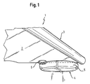
- the elastic buffer 6 is a button-shaped Projection with circular outline on the underside of the glass plate 2 and is located at the outer edge, with the glass plate 2 on the support floor bracket 4 rests.
- the bearing ribs 5 are recessed in the region of the elastic buffer 6, i. they extend only in areas where the elastic buffer 6 is not arranged is, so that not the elastic buffer, but the glass plate 2 itself directly on the support rib 5 rests (see Fig. 1). However, the elastic buffers 6 act as a stop with the support ribs 5 together.
- the stop on the glass plate 2 be positioned so that it is in the inserted position of the corresponding Carrying tray 1 of the refrigerator door facing away from the end of the corresponding Auflagrippe 5 is spaced, so that according to this spacing the support floor 1 can be pulled out a piece.
- the excerpt corresponds to the spacing between the stop and the corresponding one End of the support rib 5, the fully inserted position of the support floor is available.
- the pull-out path makes it possible, in an advantageous way, with food to load loaded tray 1 to better remove the food to be able to.
- the extraction path is marked X in FIG.
- the perpendicular to the glass plate 2 projecting height of the elastic buffer 6 is such dimensioned such that the entire thickness of the support base in the region of the elastic buffers 6, So the sum of the thickness of the glass plate 2 and the height of the elastic buffer 6, smaller is as the clear distance between two superimposed bearing ribs. 5
- the edge-covering profile strip 3 consists of a stainless steel sheet and is in their cross section in Fig. 3 shown. It has a circular arc in cross-section Curved profile rail body 7, with its concave inside is pushed over the corresponding edge of the glass plate 2. He overlaps with opposite Thighs 8 opposite sides of the glass plate 2. The free ends of the legs 8 are beaten back to the concave inside of the profile strip 3, so that they form mutually parallel support legs 9. hereby Two spring kinematics are achieved. On the one hand, the legs 8 together with the support legs 9 and feathers, which is essentially the central central region of the profile strip 3 twists. On the other hand, the support legs 9 springs relative to the legs 8.
- the support legs 9 clamp the glass plate 2 between them and cause a Clamping seat of the profile strip 3 on the glass plate 2. Gluing the profile strips 3 can be omitted hereby.
- the radius of curvature 10 of the circular arc-shaped profile profile body carcass. 7 may be about three quarters to five quarters, preferably about four fifths to six One fifth of the thickness of the glass plate 2 amount. According to the preferred shown Embodiment corresponds to the radius of curvature 10 of the arcuate profile strip body 7 the thickness of the glass plate 2.
- the circular arc-shaped profile rail body 7 extends at least over one Arc length of about ⁇ .
- the circular arc extends Moldings carcass 7 over a circular arc length of about 1 1 ⁇ 2 ⁇ .
- the folded-back support legs 9 extend over a suitable length, to achieve the desired clamping properties.
- the free ends of the support legs 9 extend at least up to the level of the center of curvature 11 back. In training of the invention, they can easily go beyond, so that the bearing surface of the Support leg 9 on the glass plate 2 is longer than the remaining glass plate surface from the end of the support leg 9 to its edge. Basically, however Other geometries of the profile strip 3 possible.
Landscapes
- Engineering & Computer Science (AREA)
- Chemical & Material Sciences (AREA)
- Combustion & Propulsion (AREA)
- Physics & Mathematics (AREA)
- Mechanical Engineering (AREA)
- Thermal Sciences (AREA)
- General Engineering & Computer Science (AREA)
- Refrigerator Housings (AREA)
- Cold Air Circulating Systems And Constructional Details In Refrigerators (AREA)
- Vibration Dampers (AREA)
- Table Equipment (AREA)
- Heat Treatments In General, Especially Conveying And Cooling (AREA)
Description
- Fig. 1
- eine perspektivische Ansicht eines in einen Kühlschrank eingesetzten Tragbodens nach einer bevorzugten Ausführung der Erfindung in einer ausschnittsweisen Darstellung, die das Aufliegen des Tragbodens an dessen vorderen Ende auf an der Seitenwandung des Innenbehälters des Kühlschranks ausgebildeten Tragrippen zeigt,
- Fig. 2
- eine perspektivische Darstellung des Tragbodens aus Fig. 1, wobei der Tragboden in einer aus dem Kühlschrank herausgenommenen Stellung gezeigt ist,
- Fig. 3
- eine Schnittansicht durch die mit einer Profilleiste eingefaßten Vorderkante des Tragbodens aus den vorhergehenden Figuren, und
- Fig. 4
- eine perspektivische Ansicht ähnlich Fig. 1 eines eingesetzten Tragbodens nach einer weiteren Ausführung der Erfindung, bei der der Tragboden durch entsprechende Positionierung des Anschlags ein vorgegebenes Stück ausgezogen werden kann.
Claims (15)
- Kühlgerät, insbesondere Kühlschrank, mit einem Tragboden und einer Tragbodenhalterung (4), wobei der Tragboden aus einem ebenen Tragbodenkorpus (2), mindestens einem daran befestigten Anschlag (6) zur Sicherung des Tragbodens gegen Herausrutschen aus einer Tragbodenhalterung (4) des Kühlgerätes, sowie einem Kantenprofil (3) an einer vorderen, einer Kühlgerätetür zugewandten Tragbodenkorpuskante besteht, wobei der Anschlag (6) separat und beabstandet von dem vorderen Kantenprofil (3) ausgebildet ist, und wobei die Tragbodenhalterung (4) aus Auflagerrippen (5) besteht,
dadurch gekennzeichnet, daß der Tragbodenkorpus aus einer Glasplatte (2) besteht, daß die Glasplatte (2) unmittelbar auf den Auflagerippen (5) aufliegt und daß der mindestens eine Anschlag (6) mit der Glasplatte (2) stoffschlüssig verbunden, insbesondere verklebt ist - Kühlgerät nach dem vorhergehenden Anspruch, wobei der Anschlag als Elastikpuffer ausgebildet ist.
- Kühlgerät nach einem der vorhergehenden Ansprüche, wobei der Anschlag (6) außerhalb der Auflagebereiche des Tragbodens, mit denen dieser auf der Tragbodenhalterung (4) des Kühlgerätes aufliegt, angeordnet ist.
- Kühlgerät nach einem der vorhergehenden Ansprüche, wobei der Anschlag (6) derart ausgebildet ist, daß er mit der Tragbodenhalterung (4) des Kühlgerätes zusammenwirkt.
- Kühlgerät nach dem Anspruch 2, wobei der Elastikpuffer (6) als knopfförmiger Vorsprung insbesondere auf der Unterseite des Tragbodens vorgesehen ist.
- Kühlgerät nach dem Anspruch 2, wobei der Elastikpuffer (6) aus Gummi bzw. Kunststoff besteht.
- Kühlgerät nach dem Anspruch 2, wobei der Elastikpuffer (6) transparent ausgebildet ist.
- Kühlgerät nach einem der vorhergehenden Ansprüche, wobei das vordere Kantenprofil als kanteneinfassende Profilleiste (3) ausgebildet ist.
- Kühlgerät nach dem vorhergehenden Anspruch, wobei als kanteneinfassende Profilleiste (3) eine Metallleiste vorgesehen ist, die zwei eine Tragbodenkante übergreifende Schenkel (8) besitzt, deren freie Enden zurückgeschlagen sind und parallele Stützschenkel (9) bilden, die auf gegenüberliegenden Oberflächen des Tragbodens aufliegen.
- Kühlgerät nach dem vorhergehenden Anspruch, wobei die Stützschenkel (9) die gegenüberliegenden Oberflächen des Tragbodens zwischen sich elastisch klemmen.
- Kühlgerät nach einem der beiden vorhergehenden Ansprüche, wobei die Profilleiste (3) einen bogenförmig, insbesondere kreisbogenförmig gekrümmten Leistenkorpus (7) besitzt, an den die Stützschenkel (9) anschließen.
- Kühlgerät nach einem der vorhergehenden Ansprüche 8-11, wobei eine Stahlblech-, insbesondere Edelstahlblech-Profilleiste (3) vorgesehen ist.
- Kühlgerät nach dem Anspruch 2, wobei mehrere, insbesondere zwei Elastikpuffer auf gegenüberliegenden Seiten des Tragbodenkorpus (2) vorgesehen sind.
- Kühlgerät nach dem Anspruch 2, wobei die Tragbodenhalterung (4) eine Aussparung aufweist, in die der Elastikpuffer (6) des Tragbodens (1) eingreift.
- Kühlgerät nach dem vorhergehenden Anspruch, wobei die als an den Innenwänden des Kühlgerätes vorgesehenen Auflagerippen (5) ausgebildete Tragbodenhalterung (4) zumindest eine Unterbrechung für den bzw. die Elastikpuffer (6) besitzt.
Applications Claiming Priority (2)
| Application Number | Priority Date | Filing Date | Title |
|---|---|---|---|
| DE20018350U | 2000-10-26 | ||
| DE20018350U DE20018350U1 (de) | 2000-10-26 | 2000-10-26 | Kühlschrank und Tragböden hierfür |
Publications (2)
| Publication Number | Publication Date |
|---|---|
| EP1202011A1 EP1202011A1 (de) | 2002-05-02 |
| EP1202011B1 true EP1202011B1 (de) | 2005-05-25 |
Family
ID=7948121
Family Applications (1)
| Application Number | Title | Priority Date | Filing Date |
|---|---|---|---|
| EP01124529A Expired - Lifetime EP1202011B1 (de) | 2000-10-26 | 2001-10-12 | Kühlschrank und Tragböden hierfür |
Country Status (4)
| Country | Link |
|---|---|
| EP (1) | EP1202011B1 (de) |
| AT (1) | ATE296431T1 (de) |
| DE (2) | DE20018350U1 (de) |
| ES (1) | ES2240302T3 (de) |
Families Citing this family (2)
| Publication number | Priority date | Publication date | Assignee | Title |
|---|---|---|---|---|
| CN102374744B (zh) * | 2010-08-17 | 2016-02-10 | 博西华家用电器有限公司 | 搁盘和使用该搁盘的冰箱 |
| DE102010062211A1 (de) * | 2010-11-30 | 2012-05-31 | BSH Bosch und Siemens Hausgeräte GmbH | Kältegerät mit einem Glasfachboden |
Family Cites Families (6)
| Publication number | Priority date | Publication date | Assignee | Title |
|---|---|---|---|---|
| US2741525A (en) * | 1953-11-09 | 1956-04-10 | Gen Electric | Stop for sliding shelf |
| DE9111140U1 (de) * | 1991-09-07 | 1993-01-07 | Licentia Patent-Verwaltungs-Gmbh, 6000 Frankfurt | Abstellplatte für Kühl- oder Gefriergeräte |
| US5243736A (en) * | 1992-03-24 | 1993-09-14 | Universal Furniture Industries, Inc. | Drawer stop |
| KR0155969B1 (ko) * | 1995-11-30 | 1999-10-01 | 김광호 | 냉장고의 선반 |
| US5813741A (en) * | 1996-01-23 | 1998-09-29 | White Consolidated Industries, Inc. | Adjustable shelf for a refrigerator |
| DE29813644U1 (de) * | 1998-07-30 | 1999-01-07 | Liebherr-Hausgeräte GmbH, 88416 Ochsenhausen | Kühlgerät mit Tragboden |
-
2000
- 2000-10-26 DE DE20018350U patent/DE20018350U1/de not_active Expired - Lifetime
-
2001
- 2001-10-12 AT AT01124529T patent/ATE296431T1/de not_active IP Right Cessation
- 2001-10-12 EP EP01124529A patent/EP1202011B1/de not_active Expired - Lifetime
- 2001-10-12 ES ES01124529T patent/ES2240302T3/es not_active Expired - Lifetime
- 2001-10-12 DE DE50106300T patent/DE50106300D1/de not_active Expired - Lifetime
Also Published As
| Publication number | Publication date |
|---|---|
| EP1202011A1 (de) | 2002-05-02 |
| ATE296431T1 (de) | 2005-06-15 |
| ES2240302T3 (es) | 2005-10-16 |
| DE20018350U1 (de) | 2002-03-07 |
| DE50106300D1 (de) | 2005-06-30 |
Similar Documents
| Publication | Publication Date | Title |
|---|---|---|
| EP2122278B1 (de) | Kältegerät mit an einer schiene aufgehängten fachböden | |
| DE102008016474A1 (de) | Haushaltsgerät mit Transportsicherung für seine Ausstattungsteile | |
| DE202015102284U1 (de) | Dreiteilige Synchron-Auszugsführung, insbesondere mit eingeschlossener bzw. verdeckt geführter Mittelschiene | |
| EP1882140B1 (de) | Innenbehälter für ein kältegerät | |
| EP2316317B1 (de) | Großküchengerät, insbesondere Tablett-Transportwagen | |
| EP1202011B1 (de) | Kühlschrank und Tragböden hierfür | |
| EP2454541B1 (de) | Kühlgutträger für ein kältegerät | |
| WO2013164179A1 (de) | Haltevorrichtung für ein tragelement eines schrankes sowie kühl-, gefrierschrank oder weinlagerungsschrank | |
| DE2918222C2 (de) | Möbel mit Schublade | |
| EP2454542B1 (de) | Kühlgutträger für ein kältegerät | |
| DE102010039626A1 (de) | Kältegerät mit Teleskopauszügen | |
| DE102018220657A1 (de) | Einlegebodenanordnung für ein Haushaltsgerät | |
| DE102014103894A1 (de) | Trennelement für einen Fachboden eines Kühlgerätes | |
| DE19916621C2 (de) | Kühlgerät mit Tragboden | |
| DE102009029137A1 (de) | Kältegerät mit ausziehbarem Kühlgutträger | |
| DE102009029136A1 (de) | Kältegerät mit ausziehbarem Kühlgutträger | |
| DE10339935A1 (de) | Kältegerät mit herausziehbarem Kühlgutträger | |
| EP1236423A1 (de) | Schubfachaufnahme | |
| EP3722712B1 (de) | Haushaltskältegerät | |
| WO2012113595A1 (de) | Bodenblech mit unterseitiger verstärkungsstrebe | |
| EP2059744A1 (de) | Kältegerät mit einem mit schiebetüren verschliessbarem behälter | |
| EP1827171B1 (de) | Ablagekorb | |
| DE3033727A1 (de) | Brotkasten mit einem schubfach fuer besteck oder andere gegenstaende | |
| DE102021112371A1 (de) | Tragrahmen für ein Tablar | |
| DE202022101932U1 (de) | Möbel |
Legal Events
| Date | Code | Title | Description |
|---|---|---|---|
| PUAI | Public reference made under article 153(3) epc to a published international application that has entered the european phase |
Free format text: ORIGINAL CODE: 0009012 |
|
| 17P | Request for examination filed |
Effective date: 20011114 |
|
| AK | Designated contracting states |
Kind code of ref document: A1 Designated state(s): AT BE CH CY DE DK ES FI FR GB GR IE IT LI LU MC NL PT SE TR |
|
| AX | Request for extension of the european patent |
Free format text: AL;LT;LV;MK;RO;SI |
|
| AKX | Designation fees paid |
Free format text: AT BE CH CY DE DK ES FI FR GB GR IE IT LI LU MC NL PT SE TR |
|
| 17Q | First examination report despatched |
Effective date: 20031029 |
|
| GRAP | Despatch of communication of intention to grant a patent |
Free format text: ORIGINAL CODE: EPIDOSNIGR1 |
|
| RAP1 | Party data changed (applicant data changed or rights of an application transferred) |
Owner name: LIEBHERR-HAUSGERAETE OCHSENHAUSEN GMBH |
|
| GRAS | Grant fee paid |
Free format text: ORIGINAL CODE: EPIDOSNIGR3 |
|
| GRAA | (expected) grant |
Free format text: ORIGINAL CODE: 0009210 |
|
| AK | Designated contracting states |
Kind code of ref document: B1 Designated state(s): AT BE CH CY DE DK ES FI FR GB GR IE IT LI LU MC NL PT SE TR |
|
| PG25 | Lapsed in a contracting state [announced via postgrant information from national office to epo] |
Ref country code: TR Free format text: LAPSE BECAUSE OF FAILURE TO SUBMIT A TRANSLATION OF THE DESCRIPTION OR TO PAY THE FEE WITHIN THE PRESCRIBED TIME-LIMIT Effective date: 20050525 Ref country code: IE Free format text: LAPSE BECAUSE OF FAILURE TO SUBMIT A TRANSLATION OF THE DESCRIPTION OR TO PAY THE FEE WITHIN THE PRESCRIBED TIME-LIMIT Effective date: 20050525 Ref country code: FI Free format text: LAPSE BECAUSE OF FAILURE TO SUBMIT A TRANSLATION OF THE DESCRIPTION OR TO PAY THE FEE WITHIN THE PRESCRIBED TIME-LIMIT Effective date: 20050525 Ref country code: NL Free format text: LAPSE BECAUSE OF FAILURE TO SUBMIT A TRANSLATION OF THE DESCRIPTION OR TO PAY THE FEE WITHIN THE PRESCRIBED TIME-LIMIT Effective date: 20050525 |
|
| REG | Reference to a national code |
Ref country code: GB Ref legal event code: FG4D Free format text: NOT ENGLISH |
|
| REG | Reference to a national code |
Ref country code: SE Ref legal event code: TRGR Ref country code: CH Ref legal event code: EP |
|
| REG | Reference to a national code |
Ref country code: IE Ref legal event code: FG4D Free format text: LANGUAGE OF EP DOCUMENT: GERMAN |
|
| REF | Corresponds to: |
Ref document number: 50106300 Country of ref document: DE Date of ref document: 20050630 Kind code of ref document: P |
|
| REG | Reference to a national code |
Ref country code: CH Ref legal event code: NV Representative=s name: BOVARD AG PATENTANWAELTE |
|
| PG25 | Lapsed in a contracting state [announced via postgrant information from national office to epo] |
Ref country code: GR Free format text: LAPSE BECAUSE OF FAILURE TO SUBMIT A TRANSLATION OF THE DESCRIPTION OR TO PAY THE FEE WITHIN THE PRESCRIBED TIME-LIMIT Effective date: 20050825 Ref country code: DK Free format text: LAPSE BECAUSE OF FAILURE TO SUBMIT A TRANSLATION OF THE DESCRIPTION OR TO PAY THE FEE WITHIN THE PRESCRIBED TIME-LIMIT Effective date: 20050825 |
|
| GBT | Gb: translation of ep patent filed (gb section 77(6)(a)/1977) |
Effective date: 20050819 |
|
| PG25 | Lapsed in a contracting state [announced via postgrant information from national office to epo] |
Ref country code: AT Free format text: LAPSE BECAUSE OF NON-PAYMENT OF DUE FEES Effective date: 20051012 Ref country code: CY Free format text: LAPSE BECAUSE OF FAILURE TO SUBMIT A TRANSLATION OF THE DESCRIPTION OR TO PAY THE FEE WITHIN THE PRESCRIBED TIME-LIMIT Effective date: 20051012 |
|
| REG | Reference to a national code |
Ref country code: ES Ref legal event code: FG2A Ref document number: 2240302 Country of ref document: ES Kind code of ref document: T3 |
|
| PG25 | Lapsed in a contracting state [announced via postgrant information from national office to epo] |
Ref country code: PT Free format text: LAPSE BECAUSE OF FAILURE TO SUBMIT A TRANSLATION OF THE DESCRIPTION OR TO PAY THE FEE WITHIN THE PRESCRIBED TIME-LIMIT Effective date: 20051027 |
|
| PG25 | Lapsed in a contracting state [announced via postgrant information from national office to epo] |
Ref country code: BE Free format text: LAPSE BECAUSE OF NON-PAYMENT OF DUE FEES Effective date: 20051031 Ref country code: LU Free format text: LAPSE BECAUSE OF NON-PAYMENT OF DUE FEES Effective date: 20051031 Ref country code: MC Free format text: LAPSE BECAUSE OF NON-PAYMENT OF DUE FEES Effective date: 20051031 |
|
| NLV1 | Nl: lapsed or annulled due to failure to fulfill the requirements of art. 29p and 29m of the patents act | ||
| REG | Reference to a national code |
Ref country code: IE Ref legal event code: FD4D |
|
| ET | Fr: translation filed | ||
| PLBE | No opposition filed within time limit |
Free format text: ORIGINAL CODE: 0009261 |
|
| STAA | Information on the status of an ep patent application or granted ep patent |
Free format text: STATUS: NO OPPOSITION FILED WITHIN TIME LIMIT |
|
| 26N | No opposition filed |
Effective date: 20060228 |
|
| PGFP | Annual fee paid to national office [announced via postgrant information from national office to epo] |
Ref country code: GB Payment date: 20060926 Year of fee payment: 6 |
|
| PGFP | Annual fee paid to national office [announced via postgrant information from national office to epo] |
Ref country code: SE Payment date: 20061023 Year of fee payment: 6 |
|
| PGFP | Annual fee paid to national office [announced via postgrant information from national office to epo] |
Ref country code: CH Payment date: 20061024 Year of fee payment: 6 |
|
| BERE | Be: lapsed |
Owner name: LIEBHERR-HAUSGERATE OCHSENHAUSEN G.M.B.H. Effective date: 20051031 |
|
| EUG | Se: european patent has lapsed | ||
| GBPC | Gb: european patent ceased through non-payment of renewal fee |
Effective date: 20071012 |
|
| REG | Reference to a national code |
Ref country code: CH Ref legal event code: PL |
|
| PG25 | Lapsed in a contracting state [announced via postgrant information from national office to epo] |
Ref country code: CH Free format text: LAPSE BECAUSE OF NON-PAYMENT OF DUE FEES Effective date: 20071031 Ref country code: LI Free format text: LAPSE BECAUSE OF NON-PAYMENT OF DUE FEES Effective date: 20071031 |
|
| PG25 | Lapsed in a contracting state [announced via postgrant information from national office to epo] |
Ref country code: SE Free format text: LAPSE BECAUSE OF NON-PAYMENT OF DUE FEES Effective date: 20071013 |
|
| PG25 | Lapsed in a contracting state [announced via postgrant information from national office to epo] |
Ref country code: GB Free format text: LAPSE BECAUSE OF NON-PAYMENT OF DUE FEES Effective date: 20071012 |
|
| REG | Reference to a national code |
Ref country code: FR Ref legal event code: PLFP Year of fee payment: 15 |
|
| REG | Reference to a national code |
Ref country code: FR Ref legal event code: PLFP Year of fee payment: 16 |
|
| REG | Reference to a national code |
Ref country code: FR Ref legal event code: PLFP Year of fee payment: 17 |
|
| REG | Reference to a national code |
Ref country code: FR Ref legal event code: PLFP Year of fee payment: 18 |
|
| PGFP | Annual fee paid to national office [announced via postgrant information from national office to epo] |
Ref country code: IT Payment date: 20181031 Year of fee payment: 18 Ref country code: ES Payment date: 20181115 Year of fee payment: 18 Ref country code: FR Payment date: 20181026 Year of fee payment: 18 |
|
| PGFP | Annual fee paid to national office [announced via postgrant information from national office to epo] |
Ref country code: DE Payment date: 20191029 Year of fee payment: 19 |
|
| PG25 | Lapsed in a contracting state [announced via postgrant information from national office to epo] |
Ref country code: IT Free format text: LAPSE BECAUSE OF NON-PAYMENT OF DUE FEES Effective date: 20191012 |
|
| REG | Reference to a national code |
Ref country code: DE Ref legal event code: R119 Ref document number: 50106300 Country of ref document: DE |
|
| PG25 | Lapsed in a contracting state [announced via postgrant information from national office to epo] |
Ref country code: FR Free format text: LAPSE BECAUSE OF NON-PAYMENT OF DUE FEES Effective date: 20191031 Ref country code: DE Free format text: LAPSE BECAUSE OF NON-PAYMENT OF DUE FEES Effective date: 20210501 |
|
| PG25 | Lapsed in a contracting state [announced via postgrant information from national office to epo] |
Ref country code: ES Free format text: LAPSE BECAUSE OF NON-PAYMENT OF DUE FEES Effective date: 20191013 |