EP1202016B1 - Installation de climatisation avec échangeur de chaleur interne et tube d'échangeur de chaleur pour une telle installation - Google Patents
Installation de climatisation avec échangeur de chaleur interne et tube d'échangeur de chaleur pour une telle installation Download PDFInfo
- Publication number
- EP1202016B1 EP1202016B1 EP01124090A EP01124090A EP1202016B1 EP 1202016 B1 EP1202016 B1 EP 1202016B1 EP 01124090 A EP01124090 A EP 01124090A EP 01124090 A EP01124090 A EP 01124090A EP 1202016 B1 EP1202016 B1 EP 1202016B1
- Authority
- EP
- European Patent Office
- Prior art keywords
- heat exchanger
- exchanger tube
- exchanger according
- outer channels
- central channel
- Prior art date
- Legal status (The legal status is an assumption and is not a legal conclusion. Google has not performed a legal analysis and makes no representation as to the accuracy of the status listed.)
- Expired - Lifetime
Links
Images
Classifications
-
- B—PERFORMING OPERATIONS; TRANSPORTING
- B60—VEHICLES IN GENERAL
- B60H—ARRANGEMENTS OF HEATING, COOLING, VENTILATING OR OTHER AIR-TREATING DEVICES SPECIALLY ADAPTED FOR PASSENGER OR GOODS SPACES OF VEHICLES
- B60H1/00—Heating, cooling or ventilating devices
- B60H1/00321—Heat exchangers for air-conditioning devices
- B60H1/00342—Heat exchangers for air-conditioning devices of the liquid-liquid type
-
- B—PERFORMING OPERATIONS; TRANSPORTING
- B60—VEHICLES IN GENERAL
- B60H—ARRANGEMENTS OF HEATING, COOLING, VENTILATING OR OTHER AIR-TREATING DEVICES SPECIALLY ADAPTED FOR PASSENGER OR GOODS SPACES OF VEHICLES
- B60H1/00—Heating, cooling or ventilating devices
- B60H1/32—Cooling devices
- B60H1/3204—Cooling devices using compression
- B60H1/3227—Cooling devices using compression characterised by the arrangement or the type of heat exchanger, e.g. condenser, evaporator
-
- B—PERFORMING OPERATIONS; TRANSPORTING
- B60—VEHICLES IN GENERAL
- B60H—ARRANGEMENTS OF HEATING, COOLING, VENTILATING OR OTHER AIR-TREATING DEVICES SPECIALLY ADAPTED FOR PASSENGER OR GOODS SPACES OF VEHICLES
- B60H1/00—Heating, cooling or ventilating devices
- B60H1/32—Cooling devices
- B60H1/3204—Cooling devices using compression
- B60H1/3229—Cooling devices using compression characterised by constructional features, e.g. housings, mountings, conversion systems
-
- F—MECHANICAL ENGINEERING; LIGHTING; HEATING; WEAPONS; BLASTING
- F25—REFRIGERATION OR COOLING; COMBINED HEATING AND REFRIGERATION SYSTEMS; HEAT PUMP SYSTEMS; MANUFACTURE OR STORAGE OF ICE; LIQUEFACTION SOLIDIFICATION OF GASES
- F25B—REFRIGERATION MACHINES, PLANTS OR SYSTEMS; COMBINED HEATING AND REFRIGERATION SYSTEMS; HEAT PUMP SYSTEMS
- F25B40/00—Subcoolers, desuperheaters or superheaters
-
- F—MECHANICAL ENGINEERING; LIGHTING; HEATING; WEAPONS; BLASTING
- F28—HEAT EXCHANGE IN GENERAL
- F28D—HEAT-EXCHANGE APPARATUS, NOT PROVIDED FOR IN ANOTHER SUBCLASS, IN WHICH THE HEAT-EXCHANGE MEDIA DO NOT COME INTO DIRECT CONTACT
- F28D7/00—Heat-exchange apparatus having stationary tubular conduit assemblies for both heat-exchange media, the media being in contact with different sides of a conduit wall
- F28D7/0008—Heat-exchange apparatus having stationary tubular conduit assemblies for both heat-exchange media, the media being in contact with different sides of a conduit wall the conduits for one medium being in heat conductive contact with the conduits for the other medium
-
- F—MECHANICAL ENGINEERING; LIGHTING; HEATING; WEAPONS; BLASTING
- F28—HEAT EXCHANGE IN GENERAL
- F28D—HEAT-EXCHANGE APPARATUS, NOT PROVIDED FOR IN ANOTHER SUBCLASS, IN WHICH THE HEAT-EXCHANGE MEDIA DO NOT COME INTO DIRECT CONTACT
- F28D7/00—Heat-exchange apparatus having stationary tubular conduit assemblies for both heat-exchange media, the media being in contact with different sides of a conduit wall
- F28D7/10—Heat-exchange apparatus having stationary tubular conduit assemblies for both heat-exchange media, the media being in contact with different sides of a conduit wall the conduits being arranged one within the other, e.g. concentrically
- F28D7/106—Heat-exchange apparatus having stationary tubular conduit assemblies for both heat-exchange media, the media being in contact with different sides of a conduit wall the conduits being arranged one within the other, e.g. concentrically consisting of two coaxial conduits or modules of two coaxial conduits
-
- F—MECHANICAL ENGINEERING; LIGHTING; HEATING; WEAPONS; BLASTING
- F28—HEAT EXCHANGE IN GENERAL
- F28F—DETAILS OF HEAT-EXCHANGE AND HEAT-TRANSFER APPARATUS, OF GENERAL APPLICATION
- F28F1/00—Tubular elements; Assemblies of tubular elements
- F28F1/02—Tubular elements of cross-section which is non-circular
- F28F1/022—Tubular elements of cross-section which is non-circular with multiple channels
-
- F—MECHANICAL ENGINEERING; LIGHTING; HEATING; WEAPONS; BLASTING
- F28—HEAT EXCHANGE IN GENERAL
- F28F—DETAILS OF HEAT-EXCHANGE AND HEAT-TRANSFER APPARATUS, OF GENERAL APPLICATION
- F28F1/00—Tubular elements; Assemblies of tubular elements
- F28F1/10—Tubular elements and assemblies thereof with means for increasing heat-transfer area, e.g. with fins, with projections, with recesses
- F28F1/40—Tubular elements and assemblies thereof with means for increasing heat-transfer area, e.g. with fins, with projections, with recesses the means being only inside the tubular element
-
- F—MECHANICAL ENGINEERING; LIGHTING; HEATING; WEAPONS; BLASTING
- F28—HEAT EXCHANGE IN GENERAL
- F28F—DETAILS OF HEAT-EXCHANGE AND HEAT-TRANSFER APPARATUS, OF GENERAL APPLICATION
- F28F7/00—Elements not covered by group F28F1/00, F28F3/00 or F28F5/00
- F28F7/02—Blocks traversed by passages for heat-exchange media
-
- F—MECHANICAL ENGINEERING; LIGHTING; HEATING; WEAPONS; BLASTING
- F28—HEAT EXCHANGE IN GENERAL
- F28F—DETAILS OF HEAT-EXCHANGE AND HEAT-TRANSFER APPARATUS, OF GENERAL APPLICATION
- F28F9/00—Casings; Header boxes; Auxiliary supports for elements; Auxiliary members within casings
- F28F9/02—Header boxes; End plates
- F28F9/0246—Arrangements for connecting header boxes with flow lines
-
- F—MECHANICAL ENGINEERING; LIGHTING; HEATING; WEAPONS; BLASTING
- F28—HEAT EXCHANGE IN GENERAL
- F28F—DETAILS OF HEAT-EXCHANGE AND HEAT-TRANSFER APPARATUS, OF GENERAL APPLICATION
- F28F9/00—Casings; Header boxes; Auxiliary supports for elements; Auxiliary members within casings
- F28F9/02—Header boxes; End plates
- F28F9/0246—Arrangements for connecting header boxes with flow lines
- F28F9/0251—Massive connectors, e.g. blocks; Plate-like connectors
-
- F—MECHANICAL ENGINEERING; LIGHTING; HEATING; WEAPONS; BLASTING
- F25—REFRIGERATION OR COOLING; COMBINED HEATING AND REFRIGERATION SYSTEMS; HEAT PUMP SYSTEMS; MANUFACTURE OR STORAGE OF ICE; LIQUEFACTION SOLIDIFICATION OF GASES
- F25B—REFRIGERATION MACHINES, PLANTS OR SYSTEMS; COMBINED HEATING AND REFRIGERATION SYSTEMS; HEAT PUMP SYSTEMS
- F25B2309/00—Gas cycle refrigeration machines
- F25B2309/06—Compression machines, plants or systems characterised by the refrigerant being carbon dioxide
- F25B2309/061—Compression machines, plants or systems characterised by the refrigerant being carbon dioxide with cycle highest pressure above the supercritical pressure
-
- F—MECHANICAL ENGINEERING; LIGHTING; HEATING; WEAPONS; BLASTING
- F25—REFRIGERATION OR COOLING; COMBINED HEATING AND REFRIGERATION SYSTEMS; HEAT PUMP SYSTEMS; MANUFACTURE OR STORAGE OF ICE; LIQUEFACTION SOLIDIFICATION OF GASES
- F25B—REFRIGERATION MACHINES, PLANTS OR SYSTEMS; COMBINED HEATING AND REFRIGERATION SYSTEMS; HEAT PUMP SYSTEMS
- F25B9/00—Compression machines, plants or systems, in which the refrigerant is air or other gas of low boiling point
- F25B9/002—Compression machines, plants or systems, in which the refrigerant is air or other gas of low boiling point characterised by the refrigerant
- F25B9/008—Compression machines, plants or systems, in which the refrigerant is air or other gas of low boiling point characterised by the refrigerant the refrigerant being carbon dioxide
Definitions
- the invention relates to a heat exchanger tube, a constructed with such a heat exchanger tube heat exchanger and an air conditioner with such a heat exchanger.
- Air conditioning systems especially air conditioning systems of motor vehicles, usually include a chiller that operates on the principle of compression.
- the main components of such a compression refrigerating machine are a compressor, a cooler (or condenser), an expansion valve, an evaporator, and an internal heat exchanger for cooling the refrigerant supplied as a refrigerant to the expansion valve and for heating the expanded refrigerant coming out of the evaporator countercurrent.
- refrigerants As an alternative to conventional refrigerants fluids have been proposed for some time, requiring a higher operating pressure. Such a fluid is, for example, CO 2 . Such refrigerants require an increased system pressure, the systems must be designed for safety reasons up to burst pressures of 700 bar.
- a conventional refrigerant suitable heat exchanger tube is shown in GB-B-1 032 990.
- the heat exchanger tube has a central tube with inwardly projecting ribs and channels grouped around it on a rim separated by radially oriented walls. Outside, the heat exchanger tube is closed by a cylindrical shell.
- DE-A-199 03 833 discloses a heat exchanger with a heat exchanger tube, which has a central channel and arranged around these outer channels.
- the heat exchanger tube is arranged as a tube coil in a container. While the central channel is leading into and out of the container as a tube, the outer channels within the container are open to allow for fluid flow and fluid outflow.
- the heat exchanger includes a heat exchanger tube defining a multi-chamber profile having a central channel and a plurality of outer channels grouped around the central channel.
- the central channel is preferably arranged centrally in the heat exchanger tube, ie the center line of the central channel coincides with the center line of the heat exchanger tube.
- the outer channels are arranged concentrically to the central channel and separated from each other by partitions.
- the intermediate walls thus extend approximately in the radial direction with respect to the central channel or its Centerline. They thus act stiffening the heat exchanger tube and allow it to interpret the central channel particularly pressure resistant. With a channel diameter of about 5 mm, compressive strengths of several 100 bar are achieved even with small other wall thicknesses of the heat exchanger tube of, for example, 1 mm to 2 mm and aluminum as the material.
- the central channel preferably has a shape deviating from the cylindrical shape.
- the cross-sectional area of the central channel is significantly smaller than the sum of the cross-sectional areas of the outer channels in the preferred embodiment of the heat exchanger tube.
- the sum of the wall surface of the outer channels is substantially higher than the wall surface of the central channel. Nevertheless, there is a very good transition between the refrigerant fluid in the central channel and the fluid in the outer channels. This in particular if the fluid in the central channel is liquid or in a supercritical state, while the fluid in the outer channels is gaseous.
- the number of partitions that separate the outer channels from each other is greater than the number of projections that protrude into the central channel. This results in a particularly high stability of the heat exchanger tube and a high pressure resistance.
- the angle the adjacent partition walls which include an outer channel between each other, about 30 °, ie there are 12 outer channels provided. However, deviations are possible here. If necessary, a little less or even more external channels can be provided.
- the outer channels are preferably wedge-shaped, ie the intermediate walls are parallel flanked.
- the outer channels are measured in the circumferential direction, preferably narrower than measured in the radial direction. Again, this serves to stiffen the profile while improving heat exchange.
- the outer channels preferably have uniform cross sections. This ensures that a pressurization of the central channel and / or the outer channels do not lead to an asymmetric load on the heat exchanger tube.
- the central channel has a deviating from the circular cross-section. This measure makes it possible to improve the heat transfer, in particular in the case of very narrow channel cross sections. Narrow channel cross-sections allow a high compressive strength even at low wall thicknesses and thus a particularly weight-saving design.
- the heat exchanger tube for constructing a heat exchanger for a high-pressure refrigerator of an air conditioning system of a motor vehicle is suitable.
- the central channel can be narrowed, for example, by four mutually opposing projections. He then has a cross-shaped cross-section, which has been found to be useful.
- the projections are then approximately triangular in cross-section, wherein they are preferably rounded at their side facing the center of the channel.
- the radius of curvature is preferably chosen to be relatively large and is approximately in the region of the height of each projection. The projections are thus limited to the interior of the central channel out approximately circular arc.
- the projections are preferably formed as ribs extending in the axial direction, i. without twisting along the central channel. They are thus currently trained.
- the ribs allow for a heat exchanger tube with smooth central channel shortening of the heat exchanger tube by about 30%.
- the thus designed heat exchanger tube can be formed as an aluminum extruded profile. Despite in the extruded profile existing welding lines in which the material of the extruded profile has merged, can be achieved without difficulty the desired compressive strength.
- the material can be AlMgSiO.5 F22.
- a heat exchanger containing the heat exchanger tube is particularly suitable for use as an internal heat exchanger in high-pressure refrigerators for air conditioning systems of motor vehicles.
- the heat exchanger tube can be bent both in an elongated form, as well as U-shaped, as well as in other ways bent, for example spiral or helically wound form, be used as a heat exchanger.
- the symmetrical profile and the stiffening numerous partition walls ensure that neither pressure changes nor temperature changes lead to significant deformations of such a heat exchanger.
- the connecting pieces are provided with a means which serves to uniformly divide the fluid provided for the outer channels into the outer channels or to remove them uniformly from the outer channels.
- a means which serves to uniformly divide the fluid provided for the outer channels into the outer channels or to remove them uniformly from the outer channels.
- This can be done with a conical prechamber with one, two or more supply holes (manifold).
- a swirl chamber may be provided which includes spin-generating means such that the fluid supplied to the outer passages rotates about the longitudinal axis of the heat exchanger tube. Very low pressure losses ⁇ p of 2 bar and less can be realized.
- Embodiments are preferred in which the connecting pieces are designed to be identical to one another at both ends of the heat exchanger tube. This has manufacturing advantages.
- the heat exchanger according to the invention is preferably used as an internal heat exchanger, wherein it exchanges heat between the entering into the evaporator fluid and from the heat exchanger to bring out coming fluid.
- the central channel preferably carries the liquid supplied to the expansion valve under high pressure or in the supercritical state fluid, while the outer channels preferably lead the gaseous, with lower pressure exiting the evaporator fluid.
- the central channel can be carried out in the basic design according to the invention, to which a profiled central channel belongs, readily be particularly pressure resistant.
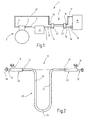
- FIG. 1 illustrates a refrigerating machine 1 for motor vehicles.
- a compressor 2 for example, is driven by the engine of the motor vehicle.
- the compressor 2 has an output 3 and an input 4. While it sucks gaseous fluid at the inlet 4, it gives off compressed fluid at the outlet 3.
- a pressure line 5 leads to a cooler 6 in which the compressed heat transfer fluid (for example CO 2 propane, butane, R 134a or ammonia) cools and / or condenses.
- the cooled and under high pressure eg between 100 bar and 150 bar for CO 2
- stationary heat transfer fluid is discharged at an output 7 of the cooler 6 to a further pressure line 8, which leads to a high-pressure inlet 9 of a heat exchanger 11.
- This has a high-pressure outlet 12, to which a pressure line 14, an expansion valve 15 is connected.
- This causes a relaxation of the heat transfer fluid, which is introduced into an evaporator 16.
- the resulting cold vapor of the heat transfer fluid is passed via a low-pressure line 17 to a low-pressure inlet 18 of the heat exchanger 11. It flows through this countercurrent to the fluid supplied via the high-pressure inlet 9. It occurs in heat exchange with this and is discharged heated at a low pressure outlet 19. From this it is supplied via a low pressure line 21 to the input 4 of the compressor 2.
- the heat exchanger 11 is illustrated separately in FIG. It has a heat exchanger tube 22, the can be designed individually and bent U-shaped in the present embodiment. It has two straight, spaced parallel to each other legs 23, 24, which are interconnected by an arcuate portion 25. The ends of the two legs 23, 24 are each bent away from each other and aligned, ie, arranged coaxially to a common axis 26.
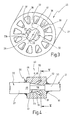
- the heat exchanger tube 22 is an extruded aluminum multi-section profile. It is shown separately in Figure 3 to illustrate its cross section.
- the heat exchanger tube 22 has a preferably cylindrical outer surface 27, which is arranged coaxially to a longitudinal central axis 28. Also coaxial with the longitudinal central axis 28, a central channel 29 is provided, which has a deviating from the circular cross-section.
- an outer diameter of the central channel 29 of 5mm to 6mm is considered appropriate. This diameter is indicated in FIG. 3 by a dashed line 31. Starting from this diameter, the central channel 29 is narrowed by four projections 32 in the exemplary embodiment, which are arranged in pairs opposite one another. If necessary, however, more (eg five or six) or fewer (eg only two or three) projections 32 may be provided.
- the projections 32 form longitudinal ribs 33 which extend parallel to the longitudinal central axis 28.
- the pointing to the longitudinal central axis 28 ends of the ribs 33rd are rounded, with the radius of curvature being approximately on the order of the height of each rib (measured from dashed line 31). If the radius is somewhat smaller, the longitudinal ribs 33 each have an approximately triangular cross section with a preferably right angle between the two flanks 33a, 33b delimiting the rib 33. If the flanks 33a, 33b are not flat but rounded, the angle between tangents to the flanks 33a, 33b is approximately 90 °.
- the heat exchanger tube 22 is integrally formed and has a plurality of outer channels 36.
- the outer channels 36 are formed equal to each other. There are at least seven, but preferably more outer channels 36 are provided. Preference is given to twelve outer channels with, as seen in Figure 3, approximately wedge-shaped cross-section.
- the outer channels 36 are separated from each other by intermediate walls 37, wherein the angle between two intermediate walls 37 is about 30 °.
- the intermediate walls 37 extend approximately parallel to the longitudinal central axis 28 and radially to this. They have a wall thickness which remains constant both in the longitudinal direction and in the radial direction. This is in the present embodiment about 1mm to 1.5mm and is smaller than the average width of an outer channel 36.
- the outer channels 36 are closed by a wall portion 38 whose thickness is approximately equal to the thickness of an intermediate wall 37 and about 1mm.
- the outer channels 36 are equidistant from one another and arranged on a coaxial with the longitudinal central axis 28 circle. Its radially inner end is spaced from the line 31 by an amount greater than the thickness of one Partition. In the present case, the distance is about 1.5mm. As a result, a sufficient wall thickness between the central channel 29 and the outer channels 36 is provided to ensure a high pressure resistance of the central channel 29.
- the central channel 29 is approximately star-shaped or cross-shaped
- the outer channels 36 are formed approximately wedge-shaped, wherein all channels 29, 36 each have rounded edges.
- the central channel 29 contacts with its wall sections having the largest diameter, the circle indicated by the line 31, while the outer channels 36 with their inner wall sections touching a line 39 through the line 39 and with their outer wall sections designated by the line 41.
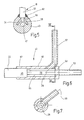
- the heat exchanger tube 22 is an integral part of the pressure-resistant heat exchanger 11. To this belong, as shown in Figure 2, also connecting pieces 42, 43 which are attached to the two ends 44, 45 of the heat exchanger tube 22 and where the high pressure inlet 9, the high pressure outlet 12th , the low-pressure inlet 18 and the low-pressure outlet 19 are arranged.
- the two connecting pieces 42, 43 are preferably identical to one another. The following description of the connection piece 43 thus applies correspondingly to the connection piece 42.
- the connecting piece 43 has an approximately cylindrical main body 46, which is provided with an opening 47 for receiving the end 45 of the heat exchanger tube 22.
- the opening 47 is first cylindrically shaped, with a diameter which approximately coincides with the diameter of the lateral surface 27 of the heat exchanger tube 22 or is slightly larger than this.
- This cylindrical portion of the opening 47 merges with an annular shoulder 48 in a conical section 49, in which the diameter of the opening 47 decreases away from the end 45.
- the opening 47 in turn merges into a cylindrical section 52.
- the cylindrical portion 52 For receiving a corresponding, for example, the high-pressure outlet 12 forming connecting piece 53, the cylindrical portion 52 then expands again to a slightly larger diameter.
- the opening 47 forms with its conical portion 49 a collecting chamber into which one or more, in the present embodiment, two diametrically opposite channels 54, 55 open. As can be seen in particular from Figure 5, these channels 54, 55 face each other and open at the conical wall of the opening 47.
- the channels 54, 55 merge in a radially arranged side chamber 56, to which e.g. the low pressure input 18 forming tubular connection piece 57 is connected.
- soldered joint instead of a welded joint, it is also possible to provide a soldered joint or, given sufficient dimensioning, an adhesive bond.
- the piece 58 may be press fit in the portion 52 of the fitting 43.
- An absolutely fluid-tight seal is also important here, because even the slightest leaks between the central channel 29 and the outer channels 36 are not permissible. If this is not sufficient, a soldering or welding connection or alternatively an adhesive connection or press connection can be provided here and / or a sealing means such as, for example, an O-ring can be used.
- the refrigerator 1 described so far operates as follows:
- the compressor 2 compresses vapor extracted from the evaporator 16. This is supplied via the low pressure line 17 to the heat exchanger 11. Here he passes through the low pressure inlet 18 first in the channels 54, 55 in equal parts. These lead the steam, the conical chamber defined by the opening 47 on two diametrically opposite sides, so that it is filled evenly. The introduced into the chamber steam can thus distribute evenly and with equal pressure to all twelve outer channels 36 and flow through the heat exchanger 11. At the opposite Connector 42 exits the heated in the heat exchanger 11 steam from the outer channels 36 and into a corresponding conical chamber. From this, the heated steam through the two channels 54, 55, in turn, the low-pressure outlet 19 is supplied. From here, the slightly heated steam reaches the compressor 22.
- the described heat exchanger 11 is inexpensive to produce and at low material usage and weight to a high degree pressure-resistant and effective. It is therefore particularly suitable for use in motor vehicles.
- the connecting pieces 42, 43 each have the task of bringing the essentially radially arranged low-pressure connections (low-pressure inlet 18, low-pressure outlet 19) into communication with the outer channels 36 in such a way that the incoming or outflowing fluid is distributed uniformly to the outer channels 36.
- the essentially axial connections (high-pressure inlet 9, high-pressure outlet 12) must be connected to the central channel 29.
- the connecting piece illustrated in FIG. 6 is representative of both connecting pieces 42, 43 43 suitable. It has a cylindrical base body 65 which encloses a cylindrical chamber 66. This has at one end an opening 67 of increased diameter and at the opposite end an opening 68 of smaller diameter.
- the end 45 of the heat exchanger tube 22 projects into the opening 67 and is fixed in this sealed. This can be soldered or welded joints, adhesive joints or press-fit joints, supported by sealants such as. O-rings serve.
- the piece 58 of the heat exchanger tube 22 extends through the chamber 66 through into the opening 68. In this it is kept sealed, for example by soldering, welding or adhesive connection or in a press fit. Following the opening 68, the tubular fitting 53 is also arranged.
- a conical chamber with at least two opposing inlets or outlets (channels 54, 55) is used in the embodiment according to Figures 6 and 7 to equalize the distribution of the fluid, a rotary or whirling movement of the fluid in the chamber 6b.
- the tubular connecting piece 57 is connected to the chamber 66 such that its tube central axis 69 does not hit the longitudinal central axis 28 of the connecting piece 43 and of the heat exchanger tube 22.
- the distance between the tube center axis 69 and the longitudinal center axis 28 is smaller than the outer diameter of the piece 58, however do not cause excessive vortex formation.
- the connector 57 is inclined slightly in the region of its mouth into the chamber 66 against the radial direction; in the embodiment of Figure 6 about 40 ° to 50 °.
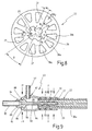
- FIG. 1 A modified embodiment of the heat exchanger tube 22 is illustrated in FIG.
- the flanks 33a, 33b form an angle ⁇ of approximately 90 ° with each other.
- the longitudinal ribs 33 are rounded at their side facing the longitudinal center axis 28 side with a radius R1, which is approximately in the order of magnitude of the height of each longitudinal rib 33 or slightly larger than this.
- the transitions between the longitudinal ribs 33 and the remaining regions of the wall of the central channel 29 are rounded with a radius R2, which is, however, preferably significantly smaller than the radius R1.
- the angle ⁇ between adjacent intermediate walls 37 is uniformly 30 ° and the wall thickness as one of the intermediate walls 37 is slightly larger (1.2mm) than the wall thickness W2 of the outer wall (1mm).
- outer channels 36 extend up to the circle marked by the dashed line 39, which is arranged concentrically to the longitudinal central axis 28.
- outer channels 36b each arranged in the region of a longitudinal rib 33, extend further inwards beyond this circle.
- W3 a wall thickness is achieved, which is achieved approximately the wall thickness W4 between the central channel 28 and the smaller outer channels 36a.
- connection of the heat exchanger tube 22 is schematically illustrated.
- a particularly advantageous embodiment of the heat exchanger tube connection is illustrated in FIG. 9.
- the heat exchanger tube 22 is taken with its end 45 in a tubular extension 81 of the connecting piece 43, which sits sealed on the lateral surface 27 of the heat exchanger tube.
- a press connection which is achieved by radial compression of the extension 81. This is indicated in Fig. 9 by arrows F.
- one or more annular grooves 82 are formed, which serve to receive in each case preferably an elastomeric O-ring 83, which serves as a sealing element.
- O-rings are considered advantageous because of their elasticity (vibration resistance).
- other elements such as e.g. Cutting rings in question, which cut into the extension 81 and in the lateral surface 27 and provide a purely metallic seal (insensitivity to fluids). It is also possible to combine cutting rings and O-rings together, e.g. in that an annular groove 82 contains an elastomeric O-ring and contains another annular groove with a metallic cutting ring.
- the extension 81 is followed by a section 84 of slightly increased diameter or not reduced in diameter by radial compression.
- This section encloses an inlet or outflow chamber 85 and is closed at the end by an end wall 86.
- the wall of the chamber 85 is laterally pierced with an opening 87, in which the connection pipe 57 soldered or is welded.
- the end wall 86 is also provided with an opening 88 in which a terminal socket 89 is seated.
- This has a cylindrical base body, whose lateral surface is provided with an annular groove 91.
- the end wall 86 engages with the edge of its opening 88 in the annular groove. This is accomplished by first making the opening 88 with a diameter that is greater than the diameter of the body. In a radial compression step, the opening 88 is then reduced by imparting a force in the direction of the arrows F1. For sealing and additional securing the end wall 86 is then welded to the connection socket 89 or otherwise connected cohesively.
- a cannula 92 extends into the central channel 29.
- the cannula 92 is provided on its outside with annular metal ribs 93, which serve as sealing elements. When radial compression (forces F), these metal ribs press into the wall of the central channel and cause a metallic seal.
- the metal ribs 93 may be formed integrally with the cannula 92. Alternatively, O-rings or other sealing elements may be provided.
- connection socket 89 has, for the connection of the central channel 29, a connection opening 94 which communicates with the channel enclosed by the cannula 92, in the process but has a larger diameter.
- this connection opening a pipe end 95 is inserted and welded to the connection socket 89 or alternatively connected otherwise.
- the terminal socket 89 forms with the outer tube part (section 84 and extension 81) a two-piece connector.
- the port base 89 has in the chamber 85 in transition to the cannula 92 a concave annular guide surface 96 which redirects flow from the radial direction in the axial direction (or vice versa).
- This baffle reduces flow losses and, in conjunction with the annular chamber 85, whose length is about as large as their diameter, causes a uniform distribution of flow to the channels 36a or uniform fluid withdrawal from these channels 36a.
- An automotive air conditioning system includes a heat exchanger 11 having a heat exchanger tube 22 having a profiled central channel 29 and outer channels 36 grouped therearound.
- This heat exchanger tube 22 is suitable for the construction of countercurrent heat exchangers.
- the heat exchanger tube 22 is to cut off to appropriate length and provided with corresponding end pieces 42, 43.
- Such heat exchangers prove to be light, pressure resistant and effective.
Landscapes
- Engineering & Computer Science (AREA)
- Physics & Mathematics (AREA)
- Thermal Sciences (AREA)
- Mechanical Engineering (AREA)
- General Engineering & Computer Science (AREA)
- Geometry (AREA)
- Heat-Exchange Devices With Radiators And Conduit Assemblies (AREA)
- Air-Conditioning For Vehicles (AREA)
Claims (24)
- Echangeur de chaleur (11) comportant un tube d'échangeur de chaleur (22) comprenant :un canal central (29) qui présente une paroi fermée depuis laquelle s'étendent plusieurs saillies (31) jusque dans le canal central (29) ;plusieurs canaux extérieurs (36) qui sont agencés concentriquement au canal central (29) et qui sont séparés l'un de l'autre par des cloisons intermédiaires (37),caractérisé en ce que :le tube d'échangeur de chaleur (22) est relié aux deux extrémités (44, 45) par des pièces de raccordement (42, 43) qui présentent respectivement un compartiment collecteur (47, 66) afin de regrouper respectivement tous les canaux extérieurs (36) en un canal, etles pièces de raccordement (42, 43) présentent un moyen pour la répartition régulière d'un flux de fluide sur les canaux extérieurs (36) ou pour le regroupement régulier du flux de fluide qui arrive des canaux extérieurs (36).
- Echangeur de chaleur selon la revendication 1, caractérisé en ce que le nombre de cloisons intermédiaires (37) du tube d'échangeur de chaleur (22) est plus grand que le nombre de saillies (31).
- Echangeur de chaleur selon la revendication 1, caractérisé en ce que les canaux extérieurs (36) du tube d'échangeur de chaleur (22) présentent respectivement sur leur côté radialement intérieur une largeur qui est plus faible que leur hauteur mesurée en direction radiale.
- Echangeur de chaleur selon la revendication 1, caractérisé en ce que les canaux extérieurs (36) du tube d'échangeur de chaleur (22) présentent respectivement sur leur côté radialement extérieur une largeur qui est plus faible que leur hauteur mesurée en direction radiale.
- Echangeur de chaleur selon la revendication 1, caractérisé en ce que les cloisons intermédiaires (37) du tube d'échangeur de chaleur (22) sont réalisées avec des flancs parallèles.
- Echangeur de chaleur selon la revendication 1, caractérisé en ce que tous les canaux extérieurs (36) du tube d'échangeur de chaleur (22) présentent des sections transversales qui coïncident.
- Echangeur de chaleur selon la revendication 1, caractérisé en ce que les canaux extérieurs (36a, 36b) du tube d'échangeur de chaleur (22) présentent au moins deux sections transversales différentes.
- Echangeur de chaleur selon la revendication 1, caractérisé en ce que toutes les cloisons intermédiaires (37) du tube d'échangeur de chaleur (22) présentent une épaisseur de cloison uniforme.
- Echangeur de chaleur selon la revendication 1, caractérisé en ce qu'une épaisseur de paroi qui est plus grande que l'épaisseur de cloison des cloisons intermédiaires (37) est prévue entre le canal central (29) du tube d'échangeur de chaleur (22) et les canaux extérieurs (36).
- Echangeur de chaleur selon la revendication 1, caractérisé en ce qu'une épaisseur de paroi qui est plus grande que l'épaisseur de paroi des zones de paroi (38) formant la terminaison des canaux extérieurs (36) vers l'extérieur, est prévue entre le canal central (29) du tube d'échangeur de chaleur (22) et les canaux extérieurs (36) du tube d'échangeur de chaleur (22).
- Echangeur de chaleur selon la revendication 1, caractérisé en ce que les canaux extérieurs (36) du tube d'échangeur de chaleur (22) présentent une section transversale en forme de coin.
- Echangeur de chaleur selon la revendication 1, caractérisé en ce que le canal central (29) du tube d'échangeur de chaleur (22) présente une section transversale en forme de croix.
- Echangeur de chaleur selon la revendication 1, caractérisé en ce que les saillies (31) du tube d'échangeur de chaleur (22) présentent une section transversale triangulaire arrondie.
- Echangeur de chaleur selon la revendication 1, caractérisé en ce que les saillies (31) du tube d'échangeur de chaleur (22) présentent des flancs qui incluent entre eux un angle droit (α).
- Echangeur de chaleur selon la revendication 1, caractérisé en ce que les saillies (31) du tube d'échangeur de chaleur (22) sont réalisées comme nervures (33).
- Echangeur de chaleur selon la revendication 15, caractérisé en ce que les nervures (33) du tube d'échangeur de chaleur (22) sont réalisées en ligne droite en direction axiale.
- Echangeur de chaleur selon la revendication 1, caractérisé en ce que le tube d'échangeur de chaleur (22) est réalisé comme profilé d'aluminium extrudé.
- Echangeur de chaleur selon la revendication 1, caractérisé en ce que le moyen pour la répartition régulière ou pour le regroupement régulier du flux de fluide est une chambre à diffuseur (47).
- Echangeur de chaleur selon la revendication 1, caractérisé en ce que le moyen pour la répartition régulière ou pour le regroupement régulier du flux de fluide est une chambre à giration (66).
- Echangeur de chaleur selon la revendication 19, caractérisé en ce que la chambre à diffuseur est réalisée en forme de cône et présente au moins deux canaux d'arrivée ou d'évacuation (54, 55).
- Echangeur de chaleur selon la revendication 19, caractérisé en ce que la chambre à giration (66) présente une section transversale sensiblement cylindrique.
- Echangeur de chaleur selon la revendication 19, caractérisé en ce que la chambre à giration présente un raccord d'arrivée ou d'évacuation (57) parallèlement décalé et incliné à l'encontre de la direction radiale.
- Echangeur de chaleur selon la revendication 1, caractérisé en ce que les pièces de raccordement (42, 43) sont réalisées de manière identique entre elles aux deux extrémités (44, 45) du tube d'échangeur de chaleur.
- Installation de climatisation (1), en particulier pour des véhicules automobiles, comprenant :un compresseur (2) pour la mise à disposition d'un fluide comprimé sur une sortie (3) ;un radiateur (6) pour le refroidissement du fluide comprimé, lequel est raccordé au compresseur (2) par l'intermédiaire d'une conduite (5) ;une soupape d'expansion (15) qui, par l'intermédiaire d'une conduite de haute pression (14), reçoit du fluide refroidi depuis le condensateur (6) et redonne ce fluide refroidi à un évaporateur (16) ;une conduite de retour (17, 21) par laquelle du fluide provenant de l'évaporateur (16) est reconduit vers le compresseur (2) ; etun échangeur de chaleur (11) selon l'une des revendications 1 à 23, dont le canal central (29) est raccordé est raccordé à la conduite de haute pression (8, 14) et dont les canaux extérieurs (36) sont raccordés à la conduite de retour (17, 21).
Priority Applications (1)
| Application Number | Priority Date | Filing Date | Title |
|---|---|---|---|
| SI200130717T SI1202016T1 (sl) | 2000-10-25 | 2001-10-10 | Priprava za klimatiziranje z notranjim toplotnim izmenjevalnikom in z zanj predvideno toploto izmenjujočo cevjo |
Applications Claiming Priority (2)
| Application Number | Priority Date | Filing Date | Title |
|---|---|---|---|
| DE10053000A DE10053000A1 (de) | 2000-10-25 | 2000-10-25 | Klimaanlage mit innerem Wärmetauscher und Wärmetauscherrohr für einen solchen |
| DE10053000 | 2000-10-25 |
Publications (3)
| Publication Number | Publication Date |
|---|---|
| EP1202016A2 EP1202016A2 (fr) | 2002-05-02 |
| EP1202016A3 EP1202016A3 (fr) | 2004-12-08 |
| EP1202016B1 true EP1202016B1 (fr) | 2007-01-17 |
Family
ID=7661072
Family Applications (1)
| Application Number | Title | Priority Date | Filing Date |
|---|---|---|---|
| EP01124090A Expired - Lifetime EP1202016B1 (fr) | 2000-10-25 | 2001-10-10 | Installation de climatisation avec échangeur de chaleur interne et tube d'échangeur de chaleur pour une telle installation |
Country Status (6)
| Country | Link |
|---|---|
| US (1) | US6883601B2 (fr) |
| EP (1) | EP1202016B1 (fr) |
| JP (1) | JP3947993B2 (fr) |
| DE (2) | DE10053000A1 (fr) |
| ES (1) | ES2278672T3 (fr) |
| SI (1) | SI1202016T1 (fr) |
Cited By (2)
| Publication number | Priority date | Publication date | Assignee | Title |
|---|---|---|---|---|
| DE102007007228A1 (de) * | 2007-02-14 | 2008-08-21 | Behr Kirchberg Gmbh | Verfahren und Vorrichtung zum Trennen von Halbzeugen für den Einsatz in leitungsintegrierten Wärmetauschern |
| DE102007042841A1 (de) | 2007-09-10 | 2009-03-12 | Behr Gmbh & Co. Kg | Anschlussvorrichtung |
Families Citing this family (46)
| Publication number | Priority date | Publication date | Assignee | Title |
|---|---|---|---|---|
| JP3676994B2 (ja) * | 2001-09-05 | 2005-07-27 | 本田技研工業株式会社 | アルミニウム中空押出形材の液圧バルジ成形方法 |
| EP1540223A1 (fr) | 2002-09-20 | 2005-06-15 | Erbslöh Aluminium GmbH | Echangeur de chaleur, procede pour produire un echangeur de chaleur, et profile composite extrude utilise dans un tel procede |
| DE10243726B4 (de) * | 2002-09-20 | 2008-03-27 | Erbslöh Aluminium Gmbh | Wärmetauscher und Verfahren zur Herstellung eines Wärmetauschers sowie stranggepresstes Verbundprofil zur Verwendung in einem solchen Verfahren |
| EP1433990A1 (fr) * | 2002-12-26 | 2004-06-30 | Calsonic Kansei Corporation | Tuyau flexible |
| DE10303595B4 (de) * | 2003-01-30 | 2005-02-17 | Visteon Global Technologies, Inc., Dearborn | Mehrkanal-Wärmeübertrager- und Anschlusseinheit |
| JP4196774B2 (ja) * | 2003-07-29 | 2008-12-17 | 株式会社デンソー | 内部熱交換器 |
| DE102004003325A1 (de) * | 2004-01-22 | 2005-08-18 | Valeo Klimasysteme Gmbh | Koaxial-Wärmetauscher, Verfahren zur Herstellung eines Koaxial-Wärmetauschers, Verfahren zum Anschließen eines Koaxial-Wärmetauschers und ringförmige Dichtung für einen Koaxial-Wärmetauscher |
| DE102005052974B4 (de) * | 2004-11-09 | 2013-03-21 | Denso Corporation | Doppelwandiges Rohr |
| JPWO2006073134A1 (ja) * | 2005-01-07 | 2008-06-12 | 株式会社ヴァレオサーマルシステムズ | 管体及びこれを用いてなる熱交換器 |
| US7565808B2 (en) * | 2005-01-13 | 2009-07-28 | Greencentaire, Llc | Refrigerator |
| JP4387974B2 (ja) * | 2005-04-25 | 2009-12-24 | パナソニック株式会社 | 冷凍サイクル装置 |
| JP5215174B2 (ja) * | 2005-05-26 | 2013-06-19 | アルファ ラヴァル コーポレイト アクチボラゲット | ステンレス鋼の物品をろう付けする方法 |
| WO2007022777A1 (fr) * | 2005-08-25 | 2007-03-01 | Knudsen Køling A/S | Échangeur de chaleur |
| DE102005043506A1 (de) * | 2005-09-12 | 2007-03-15 | Behr Gmbh & Co. Kg | Anschlussanordnung, insbesondere für einen Wärmetauscher |
| DE102005056650A1 (de) * | 2005-11-25 | 2007-05-31 | Behr Gmbh & Co. Kg | Koaxialrohr oder Rohr-in-Rohr-Anordnung, insbesondere für einen Wärmetauscher |
| DE102005056651A1 (de) * | 2005-11-25 | 2007-05-31 | Behr Gmbh & Co. Kg | Koaxialrohr oder Rohr-in-Rohr-Anordnung, insbesondere für einen Wärmetauscher |
| DE102006017816B4 (de) * | 2006-04-13 | 2008-04-24 | Eaton Fluid Power Gmbh | Innerer Kältemaschinen-Wärmetauscher |
| JP4897423B2 (ja) * | 2006-10-06 | 2012-03-14 | ホシザキ電機株式会社 | ドラム式製氷機の製氷ドラム |
| EP1923655A3 (fr) | 2006-11-14 | 2013-04-10 | Behr Kirchberg Gmbh | Agencement de raccordement, en particulier pour un échangeur thermique |
| DE102007054732A1 (de) | 2006-11-14 | 2008-07-03 | Behr Kirchberg Gmbh | Anschlussanordnung, insbesondere für einen Wärmetauscher |
| JP2008207630A (ja) * | 2007-02-23 | 2008-09-11 | Tgk Co Ltd | 車両用空調装置の内部熱交換器 |
| DE102007015186A1 (de) * | 2007-03-29 | 2008-10-02 | Valeo Klimasysteme Gmbh | Interner Wärmetauscher für eine Klimaanlage |
| FR2915561B1 (fr) * | 2007-04-27 | 2009-06-26 | Hutchinson Sa | Echangeur thermique interne pour circuit de climatisation de vehicule automobile, un tel circuit et procede de raccordement de deux connecteurs a cet echangeur |
| US7726135B2 (en) | 2007-06-06 | 2010-06-01 | Greencentaire, Llc | Energy transfer apparatus and methods |
| JP2009162395A (ja) * | 2007-12-28 | 2009-07-23 | Showa Denko Kk | 二重管式熱交換器 |
| US20090200005A1 (en) * | 2008-02-09 | 2009-08-13 | Sullivan Shaun E | Energy transfer tube apparatus, systems, and methods |
| DE102008022933B3 (de) * | 2008-05-09 | 2009-12-31 | Erbslöh Aluminium Gmbh | Koaxialprofil und Verfahren zur Herstellung eines solchen Koaxialfprofils |
| EP2116803B1 (fr) | 2008-05-09 | 2016-03-16 | Erbslöh Aluminium GmbH | Profilé coaxial et procédé de fabrication d'un tel profilé coaxial |
| DE202008006379U1 (de) | 2008-05-09 | 2008-07-17 | Erbslöh Aluminium Gmbh | Koaxialprofil |
| DE102009028487A1 (de) * | 2008-08-12 | 2010-02-25 | Visteon Global Technologies, Inc., Van Buren Township | Vorrichtung zur Kühlung eines Gasstroms |
| IT1392549B1 (it) * | 2008-11-24 | 2012-03-09 | Dytech Dynamic Fluid Tech Spa | Scambiatore di calore per un circuito di aria condizionata di un autoveicolo provvisto di un connettore perfezionato |
| DE102009044119A1 (de) | 2009-09-28 | 2011-03-31 | Contitech Kühner Gmbh & Cie. Kg | Innerer Wärmetauscher, insbesondere für Kraftfahrzeugklimaanlagen |
| FR2953917B1 (fr) * | 2009-12-10 | 2012-01-20 | Hutchinson | Echangeur thermique interne pour circuit de climatisation de vehicule automobile et un tel circuit |
| DE102010034112A1 (de) * | 2010-08-12 | 2012-02-16 | Gm Global Technology Operations Llc (N.D.Ges.D. Staates Delaware) | Interner Wärmetauscher für eine Kraftfahrzeug-Klimaanlage |
| DE102010037445A1 (de) | 2010-09-10 | 2012-03-15 | Contitech Kühner Gmbh & Cie. Kg | Kraftfahrzeugklimaanlage mit innerem Wärmetauscher |
| JP5655477B2 (ja) * | 2010-09-30 | 2015-01-21 | ダイキン工業株式会社 | 押出管、その押出管を用いた熱交換器、及びその熱交換器を用いた冷凍装置 |
| US20130167570A1 (en) * | 2011-12-30 | 2013-07-04 | Jose Bouloy | Conduit for using only at one end of, and for mildly defrosting, an evaporator without causing excessive heat to affect the evaporator or occupants in proximity to the evaporator |
| FR2995674B1 (fr) * | 2012-09-18 | 2017-10-20 | Dcns | Echangeur de chaleur a structure elementaire tubulaire d'echange thermique |
| WO2014054117A1 (fr) * | 2012-10-02 | 2014-04-10 | 三菱電機株式会社 | Échangeur de chaleur à deux tubes et dispositif à cycle de réfrigération |
| CN102897000B (zh) * | 2012-11-07 | 2016-01-27 | 奇瑞汽车股份有限公司 | 一种汽车空调系统以及汽车 |
| CN103542643B (zh) * | 2013-10-21 | 2015-08-19 | 江苏超力电器有限公司 | 一种汽车空调辅助冷凝器 |
| DE102013020469A1 (de) * | 2013-12-06 | 2015-06-11 | Webasto SE | Wärmeübertrager und Verfahren zum Herstellen eines Wärmeübertragers |
| IT201700046660A1 (it) * | 2017-04-28 | 2018-10-28 | Milano Politecnico | Cuscinetto lubrificato per macchine rotanti |
| US11002386B2 (en) | 2019-01-17 | 2021-05-11 | Fmc Technologies, Inc. | Low erosion fluid conduit with sharp section geometry |
| DE102021121252A1 (de) * | 2021-08-16 | 2023-02-16 | Audi Aktiengesellschaft | Modulbaugruppe für einen Kältemittelkreis eines Kraftfahrzeugs und Kältemittelkreis |
| DE102021214149A1 (de) * | 2021-12-10 | 2023-06-15 | Contitech Techno-Chemie Gmbh | Rohr-in-Rohr-Wärmetauscher |
Family Cites Families (17)
| Publication number | Priority date | Publication date | Assignee | Title |
|---|---|---|---|---|
| FR1259542A (fr) * | 1960-03-18 | 1961-04-28 | Alsthom Cgee | Nouvelles dispositions d'entretoises pour échangeurs de chaleur |
| BE655554A (fr) * | 1963-11-19 | |||
| US3887004A (en) * | 1972-06-19 | 1975-06-03 | Hayden Trans Cooler Inc | Heat exchange apparatus |
| US4256170A (en) * | 1979-07-20 | 1981-03-17 | Crump Robert F | Heat exchanger |
| US4345644A (en) * | 1980-11-03 | 1982-08-24 | Dankowski Detlef B | Oil cooler |
| FR2545594A1 (fr) * | 1983-05-05 | 1984-11-09 | Scoma Energie | Echangeur de chaleur |
| EP0138677A3 (fr) * | 1983-09-21 | 1985-05-22 | Office National d'Etudes et de Recherches Aérospatiales (O.N.E.R.A.) | Perfectionnements apportés aux tubes échangeurs de chaleur, aux échangeurs réalisés avec de tel tubes, et aux installations à turbines à gaz comportant de tels échangeurs |
| EP0218930A1 (fr) * | 1985-09-14 | 1987-04-22 | Norsk Hydro A/S | Refroidisseur |
| DE3605244A1 (de) * | 1986-02-19 | 1987-08-20 | Norsk Hydro As | Kuehler, beispielsweise oelkuehler |
| GB8909529D0 (en) * | 1989-04-26 | 1989-06-14 | Specialist Heat Exchangers Lim | Heat exchanger |
| JPH04132446U (ja) * | 1991-05-29 | 1992-12-08 | 本田技研工業株式会社 | 自動車のガソリン冷却装置 |
| US5326252A (en) * | 1991-09-04 | 1994-07-05 | Thomas Tonon | Catalytic combustion |
| US5375654A (en) * | 1993-11-16 | 1994-12-27 | Fr Mfg. Corporation | Turbulating heat exchange tube and system |
| DE9405062U1 (de) * | 1994-03-24 | 1994-05-26 | Hoval Interliz Ag, Vaduz-Neugut | Wärmetauscherrohr für Heizkessel |
| JPH10339588A (ja) * | 1997-06-06 | 1998-12-22 | Denso Corp | 熱交換器とその製造方法 |
| DE19903833A1 (de) * | 1999-02-01 | 2000-08-03 | Behr Gmbh & Co | Integrierte Sammler-Wärmeübertrager-Baueinheit |
| DE19944951B4 (de) * | 1999-09-20 | 2010-06-10 | Behr Gmbh & Co. Kg | Klimaanlage mit innerem Wärmeübertrager |
-
2000
- 2000-10-25 DE DE10053000A patent/DE10053000A1/de not_active Withdrawn
-
2001
- 2001-10-10 ES ES01124090T patent/ES2278672T3/es not_active Expired - Lifetime
- 2001-10-10 DE DE50111891T patent/DE50111891D1/de not_active Expired - Lifetime
- 2001-10-10 EP EP01124090A patent/EP1202016B1/fr not_active Expired - Lifetime
- 2001-10-10 SI SI200130717T patent/SI1202016T1/sl unknown
- 2001-10-23 US US10/002,670 patent/US6883601B2/en not_active Expired - Lifetime
- 2001-10-24 JP JP2001326767A patent/JP3947993B2/ja not_active Expired - Fee Related
Cited By (2)
| Publication number | Priority date | Publication date | Assignee | Title |
|---|---|---|---|---|
| DE102007007228A1 (de) * | 2007-02-14 | 2008-08-21 | Behr Kirchberg Gmbh | Verfahren und Vorrichtung zum Trennen von Halbzeugen für den Einsatz in leitungsintegrierten Wärmetauschern |
| DE102007042841A1 (de) | 2007-09-10 | 2009-03-12 | Behr Gmbh & Co. Kg | Anschlussvorrichtung |
Also Published As
| Publication number | Publication date |
|---|---|
| JP3947993B2 (ja) | 2007-07-25 |
| EP1202016A3 (fr) | 2004-12-08 |
| DE10053000A1 (de) | 2002-05-08 |
| JP2002181466A (ja) | 2002-06-26 |
| EP1202016A2 (fr) | 2002-05-02 |
| US6883601B2 (en) | 2005-04-26 |
| DE50111891D1 (de) | 2007-03-08 |
| ES2278672T3 (es) | 2007-08-16 |
| US20020046830A1 (en) | 2002-04-25 |
| SI1202016T1 (sl) | 2007-06-30 |
Similar Documents
| Publication | Publication Date | Title |
|---|---|---|
| EP1202016A2 (fr) | Installation de climatisation avec échangeur de chaleur interne et tube d'échangeur de chaleur pour une telle installation | |
| EP1845326B1 (fr) | Machines frigorifiques avec échangeur thermique interne | |
| DE10303595B4 (de) | Mehrkanal-Wärmeübertrager- und Anschlusseinheit | |
| EP0845647B1 (fr) | Echangeur de chaleur à tubes plats avec extrémité de tubes déformée par torsion | |
| DE102010025400A1 (de) | Doppelwandrohrwärmetauscher | |
| DE102011014352B4 (de) | Ejektor | |
| EP1459025A1 (fr) | Dispositif d'echange de chaleur | |
| DE60110296T2 (de) | Verbindung für doppelwandige Rohrleitungen | |
| DE102016100192B4 (de) | Vorrichtung zur Wärmeübertragung | |
| DE112015003055T5 (de) | Warmetauscher und verfahren für dessen herstellung | |
| DE102013217287A1 (de) | Innerer Wärmeübertrager für einen Kältemittelkreislauf, insbesondere für eine Klimaanlage eines Kraftfahrzeuges, und einen Kältemittelkreislauf mit einem Verdampfer | |
| DE10217581A1 (de) | Wärmetauscher-Sammlerkonstruktion | |
| EP1439367B1 (fr) | Echangeur de chaleur comprenant un connecteur relié au tube collecteur | |
| DE10346141B4 (de) | Wärmetauschereinheit | |
| DE20022757U1 (de) | Klimaanlage mit innerem Wärmetauscher und Wärmetauscherrohr für einen solchen | |
| DE102004002252A1 (de) | Wärmeübertrager für Fahrzeuge | |
| DE102017100460A1 (de) | Vorrichtung zur Wärmeübertragung in einem Kältemittelkreislauf | |
| EP1724535A2 (fr) | Echangeur de chaleur intermédiaire | |
| EP1762806A1 (fr) | Système de raccordement, en particulier pour un échangeur de chaleur | |
| EP3009780B1 (fr) | Fluide caloporteur | |
| DE102012022363A1 (de) | Interner Wärmetauscher für eine Kraftfahrzeug-Klimaanlage | |
| DE102004033099A1 (de) | Wärmeaustauscher | |
| EP1795846A1 (fr) | Échangeur de chaleur avec une pluralité d'éléments tubulaires | |
| EP1217319B1 (fr) | Echangeur de chaleur pour le transfert thermique entre un réfrigérant et un mélange eau/glycol | |
| DE10333464A1 (de) | Vorrichtung zum Austausch von Wärme |
Legal Events
| Date | Code | Title | Description |
|---|---|---|---|
| PUAI | Public reference made under article 153(3) epc to a published international application that has entered the european phase |
Free format text: ORIGINAL CODE: 0009012 |
|
| AK | Designated contracting states |
Kind code of ref document: A2 Designated state(s): AT BE CH CY DE DK ES FI FR GB GR IE IT LI LU MC NL PT SE TR |
|
| AX | Request for extension of the european patent |
Free format text: AL;LT;LV;MK;RO;SI |
|
| PUAL | Search report despatched |
Free format text: ORIGINAL CODE: 0009013 |
|
| AK | Designated contracting states |
Kind code of ref document: A3 Designated state(s): AT BE CH CY DE DK ES FI FR GB GR IE IT LI LU MC NL PT SE TR |
|
| AX | Request for extension of the european patent |
Extension state: AL LT LV MK RO SI |
|
| 17P | Request for examination filed |
Effective date: 20050602 |
|
| AKX | Designation fees paid |
Designated state(s): DE ES FR GB IT SE |
|
| AXX | Extension fees paid |
Extension state: RO Payment date: 20050602 Extension state: SI Payment date: 20050602 |
|
| GRAP | Despatch of communication of intention to grant a patent |
Free format text: ORIGINAL CODE: EPIDOSNIGR1 |
|
| GRAS | Grant fee paid |
Free format text: ORIGINAL CODE: EPIDOSNIGR3 |
|
| GRAA | (expected) grant |
Free format text: ORIGINAL CODE: 0009210 |
|
| AK | Designated contracting states |
Kind code of ref document: B1 Designated state(s): DE ES FR GB IT SE |
|
| AX | Request for extension of the european patent |
Extension state: RO SI |
|
| REG | Reference to a national code |
Ref country code: GB Ref legal event code: FG4D Free format text: NOT ENGLISH |
|
| GBT | Gb: translation of ep patent filed (gb section 77(6)(a)/1977) |
Effective date: 20070202 |
|
| REF | Corresponds to: |
Ref document number: 50111891 Country of ref document: DE Date of ref document: 20070308 Kind code of ref document: P |
|
| REG | Reference to a national code |
Ref country code: SE Ref legal event code: TRGR |
|
| ET | Fr: translation filed | ||
| REG | Reference to a national code |
Ref country code: ES Ref legal event code: FG2A Ref document number: 2278672 Country of ref document: ES Kind code of ref document: T3 |
|
| PLBE | No opposition filed within time limit |
Free format text: ORIGINAL CODE: 0009261 |
|
| STAA | Information on the status of an ep patent application or granted ep patent |
Free format text: STATUS: NO OPPOSITION FILED WITHIN TIME LIMIT |
|
| 26N | No opposition filed |
Effective date: 20071018 |
|
| PGFP | Annual fee paid to national office [announced via postgrant information from national office to epo] |
Ref country code: SE Payment date: 20141007 Year of fee payment: 14 Ref country code: ES Payment date: 20141016 Year of fee payment: 14 |
|
| PGFP | Annual fee paid to national office [announced via postgrant information from national office to epo] |
Ref country code: IT Payment date: 20141015 Year of fee payment: 14 |
|
| REG | Reference to a national code |
Ref country code: SE Ref legal event code: EUG |
|
| PG25 | Lapsed in a contracting state [announced via postgrant information from national office to epo] |
Ref country code: IT Free format text: LAPSE BECAUSE OF NON-PAYMENT OF DUE FEES Effective date: 20151010 |
|
| REG | Reference to a national code |
Ref country code: SI Ref legal event code: KO00 Effective date: 20160630 |
|
| PG25 | Lapsed in a contracting state [announced via postgrant information from national office to epo] |
Ref country code: SE Free format text: LAPSE BECAUSE OF NON-PAYMENT OF DUE FEES Effective date: 20151011 |
|
| REG | Reference to a national code |
Ref country code: FR Ref legal event code: PLFP Year of fee payment: 16 |
|
| PGFP | Annual fee paid to national office [announced via postgrant information from national office to epo] |
Ref country code: GB Payment date: 20160926 Year of fee payment: 16 |
|
| REG | Reference to a national code |
Ref country code: ES Ref legal event code: FD2A Effective date: 20161125 |
|
| PGFP | Annual fee paid to national office [announced via postgrant information from national office to epo] |
Ref country code: FR Payment date: 20160926 Year of fee payment: 16 |
|
| PGFP | Annual fee paid to national office [announced via postgrant information from national office to epo] |
Ref country code: DE Payment date: 20161031 Year of fee payment: 16 |
|
| PG25 | Lapsed in a contracting state [announced via postgrant information from national office to epo] |
Ref country code: ES Free format text: LAPSE BECAUSE OF NON-PAYMENT OF DUE FEES Effective date: 20151011 |
|
| REG | Reference to a national code |
Ref country code: DE Ref legal event code: R119 Ref document number: 50111891 Country of ref document: DE |
|
| GBPC | Gb: european patent ceased through non-payment of renewal fee |
Effective date: 20171010 |
|
| REG | Reference to a national code |
Ref country code: FR Ref legal event code: ST Effective date: 20180629 |
|
| PG25 | Lapsed in a contracting state [announced via postgrant information from national office to epo] |
Ref country code: DE Free format text: LAPSE BECAUSE OF NON-PAYMENT OF DUE FEES Effective date: 20180501 Ref country code: GB Free format text: LAPSE BECAUSE OF NON-PAYMENT OF DUE FEES Effective date: 20171010 |
|
| PG25 | Lapsed in a contracting state [announced via postgrant information from national office to epo] |
Ref country code: FR Free format text: LAPSE BECAUSE OF NON-PAYMENT OF DUE FEES Effective date: 20171031 |