EP1202024B1 - Module de capteur avec une plaque de métal découpée ( capteur magnéto résistif vanne papillon ) - Google Patents
Module de capteur avec une plaque de métal découpée ( capteur magnéto résistif vanne papillon ) Download PDFInfo
- Publication number
- EP1202024B1 EP1202024B1 EP01125622A EP01125622A EP1202024B1 EP 1202024 B1 EP1202024 B1 EP 1202024B1 EP 01125622 A EP01125622 A EP 01125622A EP 01125622 A EP01125622 A EP 01125622A EP 1202024 B1 EP1202024 B1 EP 1202024B1
- Authority
- EP
- European Patent Office
- Prior art keywords
- sensor
- metal part
- shaped sheet
- module according
- sensor module
- Prior art date
- Legal status (The legal status is an assumption and is not a legal conclusion. Google has not performed a legal analysis and makes no representation as to the accuracy of the status listed.)
- Expired - Lifetime
Links
- 239000002184 metal Substances 0.000 title claims description 29
- 238000011156 evaluation Methods 0.000 claims description 26
- 239000004020 conductor Substances 0.000 claims description 7
- 238000009434 installation Methods 0.000 claims description 3
- BGPVFRJUHWVFKM-UHFFFAOYSA-N N1=C2C=CC=CC2=[N+]([O-])C1(CC1)CCC21N=C1C=CC=CC1=[N+]2[O-] Chemical compound N1=C2C=CC=CC2=[N+]([O-])C1(CC1)CCC21N=C1C=CC=CC1=[N+]2[O-] BGPVFRJUHWVFKM-UHFFFAOYSA-N 0.000 description 7
- 238000005476 soldering Methods 0.000 description 3
- 238000005452 bending Methods 0.000 description 2
- 238000000034 method Methods 0.000 description 2
- 238000012545 processing Methods 0.000 description 2
- 238000003466 welding Methods 0.000 description 2
- 230000006978 adaptation Effects 0.000 description 1
- 238000002485 combustion reaction Methods 0.000 description 1
- 238000004891 communication Methods 0.000 description 1
- 230000001419 dependent effect Effects 0.000 description 1
- 238000013461 design Methods 0.000 description 1
- 238000005304 joining Methods 0.000 description 1
- 238000004519 manufacturing process Methods 0.000 description 1
- 239000000463 material Substances 0.000 description 1
- 238000012544 monitoring process Methods 0.000 description 1
- 238000000926 separation method Methods 0.000 description 1
- 238000012546 transfer Methods 0.000 description 1
Images
Classifications
-
- G—PHYSICS
- G01—MEASURING; TESTING
- G01D—MEASURING NOT SPECIALLY ADAPTED FOR A SPECIFIC VARIABLE; ARRANGEMENTS FOR MEASURING TWO OR MORE VARIABLES NOT COVERED IN A SINGLE OTHER SUBCLASS; TARIFF METERING APPARATUS; MEASURING OR TESTING NOT OTHERWISE PROVIDED FOR
- G01D5/00—Mechanical means for transferring the output of a sensing member; Means for converting the output of a sensing member to another variable where the form or nature of the sensing member does not constrain the means for converting; Transducers not specially adapted for a specific variable
- G01D5/12—Mechanical means for transferring the output of a sensing member; Means for converting the output of a sensing member to another variable where the form or nature of the sensing member does not constrain the means for converting; Transducers not specially adapted for a specific variable using electric or magnetic means
- G01D5/14—Mechanical means for transferring the output of a sensing member; Means for converting the output of a sensing member to another variable where the form or nature of the sensing member does not constrain the means for converting; Transducers not specially adapted for a specific variable using electric or magnetic means influencing the magnitude of a current or voltage
- G01D5/142—Mechanical means for transferring the output of a sensing member; Means for converting the output of a sensing member to another variable where the form or nature of the sensing member does not constrain the means for converting; Transducers not specially adapted for a specific variable using electric or magnetic means influencing the magnitude of a current or voltage using Hall-effect devices
- G01D5/145—Mechanical means for transferring the output of a sensing member; Means for converting the output of a sensing member to another variable where the form or nature of the sensing member does not constrain the means for converting; Transducers not specially adapted for a specific variable using electric or magnetic means influencing the magnitude of a current or voltage using Hall-effect devices influenced by the relative movement between the Hall device and magnetic fields
-
- F—MECHANICAL ENGINEERING; LIGHTING; HEATING; WEAPONS; BLASTING
- F02—COMBUSTION ENGINES; HOT-GAS OR COMBUSTION-PRODUCT ENGINE PLANTS
- F02D—CONTROLLING COMBUSTION ENGINES
- F02D11/00—Arrangements for, or adaptations to, non-automatic engine control initiation means, e.g. operator initiated
- F02D11/06—Arrangements for, or adaptations to, non-automatic engine control initiation means, e.g. operator initiated characterised by non-mechanical control linkages, e.g. fluid control linkages or by control linkages with power drive or assistance
- F02D11/10—Arrangements for, or adaptations to, non-automatic engine control initiation means, e.g. operator initiated characterised by non-mechanical control linkages, e.g. fluid control linkages or by control linkages with power drive or assistance of the electric type
- F02D11/106—Detection of demand or actuation
-
- F—MECHANICAL ENGINEERING; LIGHTING; HEATING; WEAPONS; BLASTING
- F02—COMBUSTION ENGINES; HOT-GAS OR COMBUSTION-PRODUCT ENGINE PLANTS
- F02D—CONTROLLING COMBUSTION ENGINES
- F02D9/00—Controlling engines by throttling air or fuel-and-air induction conduits or exhaust conduits
- F02D9/08—Throttle valves specially adapted therefor; Arrangements of such valves in conduits
- F02D9/10—Throttle valves specially adapted therefor; Arrangements of such valves in conduits having pivotally-mounted flaps
-
- G—PHYSICS
- G01—MEASURING; TESTING
- G01B—MEASURING LENGTH, THICKNESS OR SIMILAR LINEAR DIMENSIONS; MEASURING ANGLES; MEASURING AREAS; MEASURING IRREGULARITIES OF SURFACES OR CONTOURS
- G01B7/00—Measuring arrangements characterised by the use of electric or magnetic techniques
- G01B7/003—Measuring arrangements characterised by the use of electric or magnetic techniques for measuring position, not involving coordinate determination
-
- F—MECHANICAL ENGINEERING; LIGHTING; HEATING; WEAPONS; BLASTING
- F02—COMBUSTION ENGINES; HOT-GAS OR COMBUSTION-PRODUCT ENGINE PLANTS
- F02D—CONTROLLING COMBUSTION ENGINES
- F02D2400/00—Control systems adapted for specific engine types; Special features of engine control systems not otherwise provided for; Power supply, connectors or cabling for engine control systems
- F02D2400/08—Redundant elements, e.g. two sensors for measuring the same parameter
-
- H—ELECTRICITY
- H05—ELECTRIC TECHNIQUES NOT OTHERWISE PROVIDED FOR
- H05K—PRINTED CIRCUITS; CASINGS OR CONSTRUCTIONAL DETAILS OF ELECTRIC APPARATUS; MANUFACTURE OF ASSEMBLAGES OF ELECTRICAL COMPONENTS
- H05K3/00—Apparatus or processes for manufacturing printed circuits
- H05K3/10—Apparatus or processes for manufacturing printed circuits in which conductive material is applied to the insulating support in such a manner as to form the desired conductive pattern
- H05K3/20—Apparatus or processes for manufacturing printed circuits in which conductive material is applied to the insulating support in such a manner as to form the desired conductive pattern by affixing prefabricated conductor pattern
- H05K3/202—Apparatus or processes for manufacturing printed circuits in which conductive material is applied to the insulating support in such a manner as to form the desired conductive pattern by affixing prefabricated conductor pattern using self-supporting metal foil pattern
-
- Y—GENERAL TAGGING OF NEW TECHNOLOGICAL DEVELOPMENTS; GENERAL TAGGING OF CROSS-SECTIONAL TECHNOLOGIES SPANNING OVER SEVERAL SECTIONS OF THE IPC; TECHNICAL SUBJECTS COVERED BY FORMER USPC CROSS-REFERENCE ART COLLECTIONS [XRACs] AND DIGESTS
- Y10—TECHNICAL SUBJECTS COVERED BY FORMER USPC
- Y10T—TECHNICAL SUBJECTS COVERED BY FORMER US CLASSIFICATION
- Y10T29/00—Metal working
- Y10T29/49—Method of mechanical manufacture
- Y10T29/49002—Electrical device making
- Y10T29/49117—Conductor or circuit manufacturing
- Y10T29/49121—Beam lead frame or beam lead device
Definitions
- the invention relates to a sensor module in which a position sensor with an evaluation unit is connected, which outputs the output from the position sensor, the position of a component to be monitored corresponding signal edited.
- the signal emitted by the sensor is a Transmitter supplied, which the sensor signal for further processing prepared by a connected electronics.
- the signal of a position sensor arranged in a motor vehicle which the change in the position of a component to be monitored, such as Throttle, represented, passed to an engine control electronics, the on the basis of the sensor signal, a control signal for the control of the internal combustion engine generated.
- the sensor signal is amplified and converted and generates a zero point and / or temperature corrected output signal.
- the invention is therefore based on the object of specifying a sensor arrangement, which can be produced easily and with reduced adjustment effort.
- the object is achieved in that the position sensor and the transmitter arranged together on or on a sheet metal part are, wherein the sheet metal part at least between the sensor and transmitter formed to the electrical connection as a conductor track structure is, which is angled for adaptation to the installation location of the sensor.
- the advantage of the invention is that by the arrangement on a Sheet metal part accurate placement of the sensor to be monitored Component is possible. On line connections between sensor and transmitter can be omitted, which reduces the design of the module becomes. Sensor and transmitter become common in one step adjusted. Such a created position sensor module is not only easy in Offset and measuring range programmable, but can also for Diagnosezwekken used, such as to determine a line break or short circuit between sensor and transmitter. By Bending of the sheet metal part, in the area of the connection between sensor and Evaluation electronics, the sensor module of any mounting geometry be adjusted.
- the senor is magnetoresistive Sensor is formed, which is arranged in a magnetic field.
- the senor is approximately in the center of a cylindrical arranged permanent magnet arranged.
- bending the sheet metal part is an accurate placement of the sensor in the homogeneous part of the magnetic field possible.
- the senor is at a first outer Locked the end of the sheet metal part, wherein the evaluation in a the sensor opposite direction superior end of the sheet metal part formed by at least one free-ending conductor track of the sheet metal part is. In this way is a simple electrical connection of the sheet metal part to other electrical circuits possible.
- the free end of the sheet metal part electrically carrying a second, passive electrical components Connected sheet metal part on which the contact device is formed. Due to the use of sheet metal parts can be for the specific application necessary components arranged on this and electrically over the sheet metal part are joined together and thus form a compact Device which vibration-free, especially for use in motor vehicles is stored.
- These two sheet metal parts can with usual Connection techniques, such as welding or soldering, are contacted, as well as To protect against corrosive influences are molded, shed or housed.
- the contact device or the free end of the conductor track itself be designed as a plug-in device, thereby fixing on the a separate plug can be dispensed with.
- the senor and the transmitter housed separately.
- position sensor module are a first and a second identically constructed, each of a Sensor, a sheet metal part and an evaluation existing sensor unit present, wherein the sheet metal part of each sensor unit between Sensor and transmitter is angled approximately 90 degrees and the both sensor units inserted in the cylindrically shaped magnet are that the sensors are arranged directly above each other while the evaluation electronics of the two sensor units face each other lying in each case decentralized, arranged outside the sensor dimensions are.
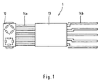
- FIG. 1 shows a sensor module 1, which consists of a magnetoresistive sensor 12 and an evaluation circuit 13 is.
- the sensor 12 is at the end of a Leadframe assembly 14 is arranged, which preferably a fine stamping frame is.
- the sensor 12th connected to the evaluation circuit 13.
- the evaluation circuit 13 is the evaluation circuit 13 with other electronic Circuit devices connectable.
- the laterally projecting from the sensor housings 12 and 22 components 15 and 25 of the lead frame assembly 14 serve as markers for exact Positioning of the sensor module 1 in the measuring field.
- the sensor 12 is designed as a magnetoresistive angle sensor and consists of two resistance bridges whose sinusoidal output signals are around 90 Degrees are out of phase.
- the transmitter 13 determines the angular position while allowing offset compensation of the angle sensor.
- connection 14a provided while the transmitter 13 five output terminals 14b for communication with external devices having.
- lead frame connections 14a and 14b both sensor signals, control signals and power signals, such as the operating voltage transfer.
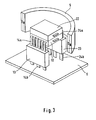
- this sensor module 11 can arbitrarily be adapted to the installation location, in which the fingers 14a between the sensor 12th and evaluation 13 are bent, which the example of Figure 2 and 3 will be explained in more detail.
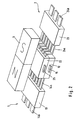
- FIG. It consists of two sensor units 1 and 2, which are constructed identically. There is the sensor unit 1 from the sensor 12, the connections 14a, the transmitter 13 and their terminals 14b.
- the second sensor unit 2 is made also from a sensor 22 and is on the sheet metal stampings 24 a with the Evaluation electronics 23 connected, which in turn stamped sheet metal parts 24 b as Connection has.
- the two sensor units 1 and 2 are arranged so the sensors 12 and 22 lie on top of each other and the evaluation electronics 13 and 23 point away from each other.
- the terminals 14b and 24b of the two sensor units properly in lie a plane, the connections 24a of the second sensor unit 2 between sensor 22 and evaluation circuit 23 twice by approximately 90 Degree bent.
- the sensors 12, 22 extends according to the longitudinal direction of the Sensor units 1, 2, a permanent magnet 5, whose magnetic field, the sensors 12 and 22 interspersed, wherein the position-dependent change of the magnetic field detected by the sensors 12 and 22 and as an output signal to the Evaluation circuits 13, 23 is supplied.
- the permanent magnet 5 is formed as a cylindrical body, wherein in the figure 3 for the sake of clarity, only a part of this magnet 5 shown is.
- the known sensors used to detect magnetic fields 12 and 22 only deliver at relatively high field strengths evaluable signals is one on the use of expensive materials in the manufacture of permanent magnets 5 instructed. For cost reasons, they try the cylindrical magnet 5 to be kept as small as possible.
- the redundant sensor units 1, 2 are arranged, which consists of the sensors 12 and 22, which are also arranged one above the other are.
- the Evaluation units 13 and 23 whose output terminals 14b or 24b are electrically connected to a circuit board 6.
- the sheet metal stampings 14a and 24a are bent approximately 90 in the sensor near 12, 22 and 90 degrees make such a very compact small sensor arrangement possible, what the cost of the entire system.
- the transmitter can analog or provide digital output signals, the transmitter to Zwekke Adjusting the bridges of the sensor and fixing the start and the end of the measuring range is programmable.
- the evaluation electronics is in addition to line and short circuit between the sensor head and evaluation also a loss of magnetic field strength detectable.
- the Ausensealgorythmus possible.
- the temperature of the Electronics monitored which in turn is readable.
- connection 14b or 24b can be connected to the connections 14b or 24b, which passive components or plug-in elements included attached become.
- the entire element is simply extrusion-coatable or in conventional joining techniques such as US E welding, wave soldering, conductive bonding, reflow soldering or laser processing editable.
Landscapes
- Engineering & Computer Science (AREA)
- Chemical & Material Sciences (AREA)
- Combustion & Propulsion (AREA)
- Mechanical Engineering (AREA)
- General Engineering & Computer Science (AREA)
- Physics & Mathematics (AREA)
- General Physics & Mathematics (AREA)
- Measurement Of Length, Angles, Or The Like Using Electric Or Magnetic Means (AREA)
- Transmission And Conversion Of Sensor Element Output (AREA)
Claims (9)
- Module de capteur, dans lequel un capteur de position (12, 22) est relié à une électronique d'évaluation (13, 23), qui met en forme le signal délivré par le capteur de position correspondant à la position d'un acteur, caractérisé par le fait que le capteur de position (12, 22) et l'électronique d'évaluation (13, 23) sont montés ensemble à ou sur une pièce usinée en tôle (14a, 14b; 24a, 24b), la pièce usinée en tôle (14a, 14b; 24a, 24b) étant au moins conçue, entre le capteur (12, 22) et l'électronique d'évaluation (13, 23), pour les relier électriquement sous la forme d'une structure à pistes conductrices (14a, 24a), qui est coudée pour l'adapter au lieu d'installation du capteur (12, 22).
- Module de capteur selon la revendication 1 caractérisé par le fait que le capteur (12, 22) est conçu comme capteur magnéto-résistif disposé dans un champ magnétique.
- Module de capteur selon la revendication 2 caractérisé par le fait que le capteur (12, 22) est disposé approximativement au centre d'un aimant permanent (5) cylindrique.
- Module de capteur selon la revendication 1 ou 2 caractérisé par le fait que le capteur (12, 22) est fixé à une première extrémité extérieure de la pièce usinée en tôle (14a, 14b; 24a, 24b) et que la deuxième extrémité de la pièce usinée en tôle (14a, 14b; 24a, 24b) dépassant de l'électronique d'évaluation (13, 23) dans une direction opposée au capteur (12, 22) est formée par au moins une piste conductrice (14b, 24b) se terminant librement.
- Module de capteur selon la revendication 4 caractérisé par le fait que l'extrémité libre (14b, 24b) de la pièce usinée en tôle (14a, 14b; 24a, 24b) est reliée électriquement à une deuxième pièce usinée en tôle, qui porte des composants électriques passifs, sur laquelle est formé un dispositif de mise en contact.
- Module de capteur selon la revendication 5 caractérisé par le fait que la première et la deuxième pièce usinée en tôle sont soudées ou brasées.
- Module de capteur selon la revendication 4 ou 5 caractérisé par le fait que le dispositif de mise en contact ou l'extrémité libre de la piste conductrice (14b, 24b) sont conçus comme dispositif enfichable.
- Module de capteur selon l'une des revendications 1 à 5 caractérisé par le fait que le capteur (12, 22) et/ou l'électronique d'évaluation (13, 23) sont logés dans des boítiers séparés.
- Module de capteur selon l'une des revendications 1 à 5 caractérisé par le fait qu'il renferme une première et une deuxième unité de captage (1, 2), constituées d'une façon identique chacune d'un capteur (12; 22), d'une pièce usinée en tôle (14a, 14b; 24a, 24b) et d'une électronique d'évaluation (13; 23), la pièce usinée en tôle (14a, 14b; 24a, 24b) de chaque unité de captage étant pliée approximativement à 90 degrés entre le capteur et l'électronique d'évaluation et les deux unités de captage (1, 2) étant engagées dans l'aimant permanent (5), conçu sous une forme cylindrique, de telle manière que les capteurs (12; 22) sont disposés directement l'un au-dessus de l'autre, alors que les électroniques d'évaluation (13; 23) sont disposées d'une façon décentralisée au-delà des dimensions des capteurs.
Applications Claiming Priority (2)
| Application Number | Priority Date | Filing Date | Title |
|---|---|---|---|
| DE20018538U | 2000-10-27 | ||
| DE20018538U DE20018538U1 (de) | 2000-10-27 | 2000-10-27 | Sensormodul |
Publications (2)
| Publication Number | Publication Date |
|---|---|
| EP1202024A1 EP1202024A1 (fr) | 2002-05-02 |
| EP1202024B1 true EP1202024B1 (fr) | 2005-03-23 |
Family
ID=7948265
Family Applications (1)
| Application Number | Title | Priority Date | Filing Date |
|---|---|---|---|
| EP01125622A Expired - Lifetime EP1202024B1 (fr) | 2000-10-27 | 2001-10-26 | Module de capteur avec une plaque de métal découpée ( capteur magnéto résistif vanne papillon ) |
Country Status (3)
| Country | Link |
|---|---|
| US (1) | US6593732B2 (fr) |
| EP (1) | EP1202024B1 (fr) |
| DE (2) | DE20018538U1 (fr) |
Cited By (2)
| Publication number | Priority date | Publication date | Assignee | Title |
|---|---|---|---|---|
| US8629520B2 (en) | 2006-01-20 | 2014-01-14 | Allegro Microsystems, Llc | Arrangements for an integrated sensor |
| US10935612B2 (en) | 2018-08-20 | 2021-03-02 | Allegro Microsystems, Llc | Current sensor having multiple sensitivity ranges |
Families Citing this family (23)
| Publication number | Priority date | Publication date | Assignee | Title |
|---|---|---|---|---|
| JP3794937B2 (ja) * | 2001-05-30 | 2006-07-12 | 株式会社日立製作所 | 回転検出装置 |
| DE10233080A1 (de) * | 2002-07-19 | 2004-02-12 | Fernsteuergeräte Kurt Oelsch GmbH | Sensoreinrichtung |
| TW557610B (en) * | 2002-07-31 | 2003-10-11 | Fci Asia Technology Pte Ltd | Sensor module for card connector and card connector having such sensor module |
| KR20050069078A (ko) * | 2003-12-30 | 2005-07-05 | 현대자동차주식회사 | 엔진의 연료 분사 제어방법 |
| EP2325665B1 (fr) | 2004-02-02 | 2012-11-21 | Aisan Kogyo Kabushiki Kaisha | Capteur d'angle de rotation, procédé de fabrication du capteur et dispositif de commande des gaz présentant le capteur d'angle de rotation |
| EP1718937B1 (fr) | 2004-02-24 | 2012-06-13 | Prettl, Rolf | Support de capteur et procede de realisation associe |
| US20070169551A1 (en) * | 2005-06-13 | 2007-07-26 | Analog Devices, Inc. | MEMS Sensor System with Configurable Signal Module |
| WO2007041465A1 (fr) * | 2005-09-29 | 2007-04-12 | Timken Us Corporation | Capteur d’angle redondant |
| DE102005060713B4 (de) * | 2005-12-19 | 2019-01-24 | Austriamicrosystems Ag | Magnetfeldsensoranordnung und Verfahren zur berührungslosen Messung eines Magnetfeldes |
| US20080110435A1 (en) * | 2006-11-13 | 2008-05-15 | Oswald Baasch | Air valve and method of use |
| EP1925904B1 (fr) * | 2006-11-21 | 2009-05-06 | C.R.F. Società Consortile per Azioni | Procédé et dispositif pour déterminer la position relative de deux éléments qui sont mobiles l'un par rapport à l'autre |
| US8933691B2 (en) * | 2007-10-27 | 2015-01-13 | Walbro Engine Management, L.L.C. | Rotary position sensor |
| US8857464B2 (en) | 2008-01-30 | 2014-10-14 | Flowserve Management Company | Valve actuators having magnetic angle sensors |
| US8686717B2 (en) * | 2008-09-08 | 2014-04-01 | GM Global Technology Operations LLC | Position sensor arrangement |
| DE102010020230B4 (de) * | 2010-05-11 | 2012-03-01 | Pierburg Gmbh | Stelleinheit mit Sensor, Einsteckwerkzeug sowie ein Verfahren zur Positionierung des Sensors |
| DE102010047128A1 (de) * | 2010-09-30 | 2012-04-05 | Infineon Technologies Ag | Hallsensoranordnung zum redundanten Messen eines Magnetfeldes |
| DE102013213053A1 (de) * | 2013-07-04 | 2015-01-08 | Continental Automotive Gmbh | Drehwinkelsensorvorrichtung mit redundanten Sensoreinheiten |
| KR102060031B1 (ko) * | 2014-07-22 | 2019-12-27 | 어탑 에스.피.에이. | 전기자 코일의 코일 연결부의 전기 저항 결정 방법 및 장치 |
| JP6759704B2 (ja) * | 2016-05-19 | 2020-09-23 | 株式会社ジェイテクト | センサユニット及びセンサ装置 |
| EP3494362A4 (fr) * | 2016-08-02 | 2020-03-11 | Servosense (SMC) Ltd. | Codeur absolu haute résolution |
| JP2018040586A (ja) * | 2016-09-05 | 2018-03-15 | 株式会社デンソー | 角度検出機構、及び角度検出システム |
| EP3457154B1 (fr) | 2017-09-13 | 2020-04-08 | Melexis Technologies SA | Rejet de champ parasite dans des capteurs magnétiques |
| US11567108B2 (en) | 2021-03-31 | 2023-01-31 | Allegro Microsystems, Llc | Multi-gain channels for multi-range sensor |
Family Cites Families (23)
| Publication number | Priority date | Publication date | Assignee | Title |
|---|---|---|---|---|
| JPS54148578A (en) * | 1978-04-18 | 1979-11-20 | Nec Corp | Rotating direction detector |
| JPS57193094A (en) * | 1981-05-18 | 1982-11-27 | Matsushita Electric Industrial Co Ltd | Electronic circuit part and method of mounting same |
| JPH0285324U (fr) * | 1988-12-21 | 1990-07-04 | ||
| JPH04284661A (ja) * | 1991-03-13 | 1992-10-09 | Toshiba Corp | 半導体装置 |
| DE4123407A1 (de) * | 1991-07-15 | 1993-01-21 | Holzer Walter | Hochfrequenz-stromversorgung |
| JP3206204B2 (ja) * | 1992-05-22 | 2001-09-10 | 株式会社デンソー | スロットルポジションセンサ |
| ES2176312T3 (es) * | 1993-12-22 | 2002-12-01 | Continental Teves Ag & Co Ohg | Dispositivo para detectar movimientos de giro o angulares. |
| DE4404265C3 (de) * | 1994-02-10 | 2001-02-15 | Siemens Ag | Verfahren zur Herstellung einer kalibrierten Sensoreinheit |
| US6169254B1 (en) * | 1994-07-20 | 2001-01-02 | Honeywell, Inc. | Three axis sensor package on flexible substrate |
| JP3637634B2 (ja) * | 1994-08-25 | 2005-04-13 | 株式会社デンソー | 位置センサ |
| JP3395402B2 (ja) * | 1994-10-14 | 2003-04-14 | 住友電気工業株式会社 | 移動量検出器 |
| US5488294A (en) * | 1995-01-18 | 1996-01-30 | Honeywell Inc. | Magnetic sensor with means for retaining a magnet at a precise calibrated position |
| DE19505759C2 (de) * | 1995-02-20 | 1997-02-13 | Siemens Ag | Schalter mit einem Hall-Differenz-IC für berührungslose Positionsabfrage, insbesondere im Kfz-Bereich |
| US5581179A (en) * | 1995-05-31 | 1996-12-03 | Allegro Microsystems, Inc. | Hall-effect ferrous-article-proximity sensor assembly |
| US5670876A (en) * | 1995-11-14 | 1997-09-23 | Fisher Controls International, Inc. | Magnetic displacement sensor including first and second flux paths wherein the first path has a fixed reluctance and a sensor disposed therein |
| US5631557A (en) * | 1996-02-16 | 1997-05-20 | Honeywell Inc. | Magnetic sensor with encapsulated magnetically sensitive component and magnet |
| US5912556A (en) * | 1996-11-06 | 1999-06-15 | Honeywell Inc. | Magnetic sensor with a chip attached to a lead assembly within a cavity at the sensor's sensing face |
| US6003369A (en) * | 1997-05-19 | 1999-12-21 | Continental Teves, Inc. | Method for manufacturing encapsulated semiconductor devices |
| US5963028A (en) * | 1997-08-19 | 1999-10-05 | Allegro Microsystems, Inc. | Package for a magnetic field sensing device |
| DE19747177C2 (de) * | 1997-10-07 | 2003-08-21 | Fraunhofer Ges Forschung | Gehäustes Bauelement und Verfahren zu dessen Herstellung |
| JPH11304894A (ja) * | 1998-04-23 | 1999-11-05 | Mitsubishi Electric Corp | 磁気検出装置とその製造方法 |
| DE19902188A1 (de) * | 1999-01-21 | 2000-07-27 | Philips Corp Intellectual Pty | Anordnung zur Drehzahlmessung |
| US6455907B1 (en) * | 2000-09-14 | 2002-09-24 | Delphi Technologies, Inc. | Magnetoresistive sensor assembly and method for manufacturing same |
-
2000
- 2000-10-27 DE DE20018538U patent/DE20018538U1/de not_active Expired - Lifetime
-
2001
- 2001-10-26 EP EP01125622A patent/EP1202024B1/fr not_active Expired - Lifetime
- 2001-10-26 DE DE50105676T patent/DE50105676D1/de not_active Expired - Lifetime
- 2001-10-31 US US10/004,298 patent/US6593732B2/en not_active Expired - Lifetime
Cited By (6)
| Publication number | Priority date | Publication date | Assignee | Title |
|---|---|---|---|---|
| US8629520B2 (en) | 2006-01-20 | 2014-01-14 | Allegro Microsystems, Llc | Arrangements for an integrated sensor |
| US8952471B2 (en) | 2006-01-20 | 2015-02-10 | Allegro Microsystems, Llc | Arrangements for an integrated sensor |
| US9082957B2 (en) | 2006-01-20 | 2015-07-14 | Allegro Microsystems, Llc | Arrangements for an integrated sensor |
| US9859489B2 (en) | 2006-01-20 | 2018-01-02 | Allegro Microsystems, Llc | Integrated circuit having first and second magnetic field sensing elements |
| US10069063B2 (en) | 2006-01-20 | 2018-09-04 | Allegro Microsystems, Llc | Integrated circuit having first and second magnetic field sensing elements |
| US10935612B2 (en) | 2018-08-20 | 2021-03-02 | Allegro Microsystems, Llc | Current sensor having multiple sensitivity ranges |
Also Published As
| Publication number | Publication date |
|---|---|
| DE50105676D1 (de) | 2005-04-28 |
| DE20018538U1 (de) | 2002-03-07 |
| US6593732B2 (en) | 2003-07-15 |
| EP1202024A1 (fr) | 2002-05-02 |
| US20020067162A1 (en) | 2002-06-06 |
Similar Documents
| Publication | Publication Date | Title |
|---|---|---|
| EP1202024B1 (fr) | Module de capteur avec une plaque de métal découpée ( capteur magnéto résistif vanne papillon ) | |
| EP1435524B1 (fr) | Dispositif capteur pour batterie | |
| EP2845299B1 (fr) | Moteur à courant continu pour entraîner des organes d'un véhicule automobile | |
| DE10160845A1 (de) | Halteplatte für einen Elektromotor und Elektromotor | |
| DE10130118A1 (de) | Relaisträgervorrichtung für einen Elektromotor, insbesondere für einen elektronisch kommunitierten Gleichstrommotor | |
| DE102012218847A1 (de) | Anschlusselement für eine Antriebsanordnung sowie eine Antriebsanordnung mit einem Anschlussteil | |
| DE10007868B4 (de) | Elektronische Steuerschaltung | |
| DE4320939A1 (de) | Dichtung | |
| EP2347221A1 (fr) | Dispositif pour détecter un angle de rotation d'une partie rotative | |
| DE102012211749A1 (de) | Messwiderstand für Stromsensor und Stromsensoreinheit | |
| DE112020003914T5 (de) | Elektrisch angetriebene Antriebsvorrichtung und Verfahren zum Montieren einer elektrisch angetriebenen Antriebsvorrichtung | |
| DE19649906C2 (de) | Sensor zur Erfassung von Drehwinkeln | |
| EP3109951B1 (fr) | Composant electrique, unite de connexion comprenant au moins un composant electrique, vehicule ainsi equipe et procede de fabrication d'un composant electrique | |
| DE102016203560B4 (de) | Aktoranordnung mit einem Sensormodul für einen Aktor mit verschiebbarem Anker | |
| DE19835782A1 (de) | Ultrschallwandler mit in Wandlerlängsrichtung angeordneter Platine für eine elektrische Schaltung | |
| WO2003098226A1 (fr) | Fixation pour composant electrique et procede de production correspondant | |
| DE10107630B4 (de) | Stiftleiste und Sensorsystem für Kraftfahrzeuge mit derartiger Stiftleiste | |
| DE69903057T2 (de) | Verbesserungen in verbindung mit einer servolenkung | |
| WO2008125371A1 (fr) | Système de mise en contact avec amortisseur de vibrations pour arrangements de mesure du courant | |
| WO1991009408A1 (fr) | Potentiometre pour angles de rotation | |
| WO2006008217A1 (fr) | Capteur pour mesurer la position d'un element de reglage | |
| DE102018104886B3 (de) | Elektromechanischer Fahrwerksaktuator | |
| DE19612599A1 (de) | Anordnung zur Befestigung eines Kabelbaums an einer Trägerplatte | |
| WO2007054557A1 (fr) | Ensemble capteur | |
| EP4700395A1 (fr) | Système de mise en contact pour mettre en contact un module électronique avec une carte de circuit imprimé et résistance de mesure dotée d'un tel système de mise en contact |
Legal Events
| Date | Code | Title | Description |
|---|---|---|---|
| PUAI | Public reference made under article 153(3) epc to a published international application that has entered the european phase |
Free format text: ORIGINAL CODE: 0009012 |
|
| AK | Designated contracting states |
Kind code of ref document: A1 Designated state(s): AT BE CH CY DE DK ES FI FR GB GR IE IT LI LU MC NL PT SE TR Kind code of ref document: A1 Designated state(s): DE FR GB |
|
| AX | Request for extension of the european patent |
Free format text: AL;LT;LV;MK;RO;SI |
|
| 17P | Request for examination filed |
Effective date: 20020603 |
|
| AKX | Designation fees paid |
Free format text: DE FR GB |
|
| GRAP | Despatch of communication of intention to grant a patent |
Free format text: ORIGINAL CODE: EPIDOSNIGR1 |
|
| GRAS | Grant fee paid |
Free format text: ORIGINAL CODE: EPIDOSNIGR3 |
|
| GRAA | (expected) grant |
Free format text: ORIGINAL CODE: 0009210 |
|
| AK | Designated contracting states |
Kind code of ref document: B1 Designated state(s): DE FR GB |
|
| REG | Reference to a national code |
Ref country code: GB Ref legal event code: FG4D Free format text: NOT ENGLISH |
|
| REG | Reference to a national code |
Ref country code: IE Ref legal event code: FG4D Free format text: GERMAN |
|
| REF | Corresponds to: |
Ref document number: 50105676 Country of ref document: DE Date of ref document: 20050428 Kind code of ref document: P |
|
| GBT | Gb: translation of ep patent filed (gb section 77(6)(a)/1977) |
Effective date: 20050516 |
|
| PLBE | No opposition filed within time limit |
Free format text: ORIGINAL CODE: 0009261 |
|
| STAA | Information on the status of an ep patent application or granted ep patent |
Free format text: STATUS: NO OPPOSITION FILED WITHIN TIME LIMIT |
|
| ET | Fr: translation filed | ||
| 26N | No opposition filed |
Effective date: 20051227 |
|
| REG | Reference to a national code |
Ref country code: FR Ref legal event code: TP |
|
| REG | Reference to a national code |
Ref country code: GB Ref legal event code: 732E Free format text: REGISTERED BETWEEN 20110825 AND 20110831 |
|
| PGFP | Annual fee paid to national office [announced via postgrant information from national office to epo] |
Ref country code: GB Payment date: 20141021 Year of fee payment: 14 |
|
| REG | Reference to a national code |
Ref country code: FR Ref legal event code: PLFP Year of fee payment: 15 |
|
| GBPC | Gb: european patent ceased through non-payment of renewal fee |
Effective date: 20151026 |
|
| PG25 | Lapsed in a contracting state [announced via postgrant information from national office to epo] |
Ref country code: GB Free format text: LAPSE BECAUSE OF NON-PAYMENT OF DUE FEES Effective date: 20151026 |
|
| REG | Reference to a national code |
Ref country code: FR Ref legal event code: PLFP Year of fee payment: 16 |
|
| REG | Reference to a national code |
Ref country code: FR Ref legal event code: PLFP Year of fee payment: 17 |
|
| REG | Reference to a national code |
Ref country code: FR Ref legal event code: PLFP Year of fee payment: 18 |
|
| PGFP | Annual fee paid to national office [announced via postgrant information from national office to epo] |
Ref country code: FR Payment date: 20191028 Year of fee payment: 19 |
|
| REG | Reference to a national code |
Ref country code: DE Ref legal event code: R084 Ref document number: 50105676 Country of ref document: DE |
|
| REG | Reference to a national code |
Ref country code: DE Ref legal event code: R081 Ref document number: 50105676 Country of ref document: DE Owner name: VITESCO TECHNOLOGIES GMBH, DE Free format text: FORMER OWNER: CONTINENTAL AUTOMOTIVE GMBH, 30165 HANNOVER, DE |
|
| PGFP | Annual fee paid to national office [announced via postgrant information from national office to epo] |
Ref country code: DE Payment date: 20201031 Year of fee payment: 20 |
|
| PG25 | Lapsed in a contracting state [announced via postgrant information from national office to epo] |
Ref country code: FR Free format text: LAPSE BECAUSE OF NON-PAYMENT OF DUE FEES Effective date: 20201031 |
|
| REG | Reference to a national code |
Ref country code: DE Ref legal event code: R071 Ref document number: 50105676 Country of ref document: DE |
|
| REG | Reference to a national code |
Ref country code: DE Ref legal event code: R081 Ref document number: 50105676 Country of ref document: DE Owner name: VITESCO TECHNOLOGIES GMBH, DE Free format text: FORMER OWNER: VITESCO TECHNOLOGIES GMBH, 30165 HANNOVER, DE |