EP1202044A2 - Polarimetrieverfahren - Google Patents
Polarimetrieverfahren Download PDFInfo
- Publication number
- EP1202044A2 EP1202044A2 EP01125160A EP01125160A EP1202044A2 EP 1202044 A2 EP1202044 A2 EP 1202044A2 EP 01125160 A EP01125160 A EP 01125160A EP 01125160 A EP01125160 A EP 01125160A EP 1202044 A2 EP1202044 A2 EP 1202044A2
- Authority
- EP
- European Patent Office
- Prior art keywords
- rotation
- angle
- polarimetry
- sample
- denotes
- Prior art date
- Legal status (The legal status is an assumption and is not a legal conclusion. Google has not performed a legal analysis and makes no representation as to the accuracy of the status listed.)
- Withdrawn
Links
Images


Classifications
-
- G—PHYSICS
- G01—MEASURING; TESTING
- G01N—INVESTIGATING OR ANALYSING MATERIALS BY DETERMINING THEIR CHEMICAL OR PHYSICAL PROPERTIES
- G01N21/00—Investigating or analysing materials by the use of optical means, i.e. using sub-millimetre waves, infrared, visible or ultraviolet light
- G01N21/17—Systems in which incident light is modified in accordance with the properties of the material investigated
- G01N21/21—Polarisation-affecting properties
Definitions
- the present invention relates to a method of polarimetry for use in an identification, examination on the purity, determination of the concentration, and the like of a solute in a sample solution.
- a polarimeter is employed as an optical rotation detecting type saccharimeter for detecting the concentrations of fructose, sucrose, glucose, and the like contained in an aqueous solution. Such a polarimeter can also determine especially the concentrations of spontaneously optical active substances such as glucose and protein in a urine and, therefore, is expected to come into wide use as a urinalysis equipment which requires no consumable items such as test papers.
- FIG. 7 shows a conceptual constitution of one example of conventional polarimeters.
- the polarimeter is for determining the magnitude of spontaneously optical rotatory power, i.e., an angle of rotation attributed to a spontaneously optical rotatory power of a spontaneously optical active substance in a sample.
- the angle of spontaneously optical rotation is determined on the basis of an angle of magneto-rotation (so called compensated value) by an optical Faraday effect when the spontaneously optical rotation attributed to the spontaneously optical active substance is canceled (compensated) by the magneto-rotation.
- a light source 14 for projecting a substantially parallel light configured with a sodium lamp, a band-pass filter, a lens, a slit and the like, projects a substantially parallel light composed of, for example, a sodium D ray having a wavelength of 589 nm.
- a polarizer 15 transmits only a component that has a specific plane of vibration out of the incident light projected from the light source 14.
- a sample cell 16 for holding a sample has a pair of mutually opposing transparent transmission surfaces, and is arranged so that the light projected from the light source 14 can transmit through the inside thereof.
- An analyzer 17 transmits only a component that has another specific plane of vibration out of the light transmitted through the sample cell 16.
- the relative angle ⁇ formed between the transmission axis of the polarizer 15 and the transmission axis of the analyzer 17 is fixed at ⁇ /2.
- a photosensor 18 detects the component transmitted through the analyzer 17 out of the light projected from the light source 14.
- a Faraday cell 19 functions as an optical modulator for modulating and controlling the plane of vibration of the light projected from the light source 14 on the basis of a modulation signal outputted from a signal generator 23 and a control signal outputted from a computer 22.
- the Faraday cell 19 is driven by a Faraday cell driver 20.
- a lock-in amplifier 21 performs a phase sensitive detection on the output signal from the photosensor 18 by using the modulation signal outputted from the signal generator 23 as a reference signal.
- the computer 22 calculates the angle of rotation attributed to the sample accommodated in the sample cell 16 on the basis of the control signal, and the output signal from the lock-in amplifier 21.
- Equation (8) indicates that "I” does not contain the modulation frequency component " ⁇ " in this case. Approximately considering this, i.e., assuming that the angle of rotation attributed to the sample and the amplitude of the modulation are small,
- a conventional examination method for examining glucose, protein and the like in a urine there is a method in which a test paper or the like containing a reagent is dipped in a urine, and the color reaction thereof is observed by means of a spectroscope or the like.
- This method requires the use of a consumable article such as a test paper.
- the angle of rotation attributed to the urine is measured by means of the high precision polarimeter described above, it is possible to detect the angles of rotation attributed to optical active substances present in the urine at a low concentration such as glucose and protein. Consequently, it is possible to calculate the concentrations thereof on the basis of the detected values. As a result of this, it becomes possible to examine the glucose and protein concentrations in a urine without any consumable article.
- a feedback loop is preferably constructed to control " ⁇ " so that "S" becomes zero. For this reason, " ⁇ " is desirably changed continuously.
- the present invention relates to a method of polarimetry by allowing a light with a known polarization direction "X" to be incident upon a sample, detecting a polarization direction of a light transmitted through the sample, and measuring an angle of rotation of a polarization direction in the sample on the basis of the difference between the polarization directions of the incident light and the transmitted light, the method comprising the steps of:
- At least one measuring point "Pj" (Xj, Yj), where Xj ⁇ Xi, other than the 3 or more measuring points "Pi" (Xi, Yi) is measured in the repeated measurement.
- the polarization direction "X" of the incident light is discretely changed into 3 or more polarization signals "Xi”.
- the calculated angle of rotation is judged effective when the "A" is not less than a prescribed minimum value or not more than a prescribed maximum value.
- the prescribed maximum value of the "A" is one calculated when a sample having a maximum transmittance is measured out of samples to be measured.
- the reliability of the calculated angle of rotation is evaluated on the basis of the fit between the measuring points "Pi" and the regression line.
- the calculated angle of rotation is judged effective when the index is not more than a prescribed maximum value and/or not less than a prescribed minimum value. In concrete, it is preferable that the calculated angle of rotation is judged effective when the "C" and/or the "D" is not more than a prescribed maximum value and/or when the "R" is not less than a prescribed minimum value.
- the present invention also relates to a method of polarimetry by applying a magnetic field to a sample containing a spontaneously optical active substance and a magneto-optical active substance, allowing a light with a known polarization direction "X" to be incident upon the sample, changing and modulating a polarization direction of a light transmitted through the sample, and calculating an angle of rotation attributed to the sample on the basis of a magnitude of the magnetic field when an amount of change in an angle of rotation attributed to the spontaneously optical active substance and an amount of change in an angle of rotation attributed to the magnetic field satisfy a prescribed relation, the method comprising the steps of:
- the measurement action is stopped to stop the paolarimetry for the sample.
- At least one measuring point "Pj" (Xj, Yj), where Xj ⁇ Xi, other than the 3 or more measuring points "Pi" (Xi, Yi) is measured in the repeated measurement.
- the magnetic field strength is discretely changed into 3 or more magnetic field strengths.
- the calculated angle of rotation is judged effective when the "A" is not less than a prescribed minimum value or not more than a prescribed maximum value.
- the prescribed maximum value of the "A" is one calculated when a sample having a maximum transmittance is measured out of samples to be measured.
- the reliability of the calculated angle of rotation is evaluated on the basis of the fit between the measuring points "Pi" and the regression line.
- C ⁇ ( ⁇ i) 2
- ⁇ i Yi - A - B ⁇ Xi
- i denotes an integer of 1 to n, where n is 3 or more
- ⁇ denotes the total sum when the values of "i” are from n to 1
- the calculated angle of rotation is judged effective when the index is not more than a prescribed maximum value and/or not less than a prescribed minimum value. In concrete, it is preferable that the calculated angle of rotation is judged effective when the "C" and/or the "D" is not more than a prescribed maximum value and/or when the "R" is not less than a prescribed minimum value.
- the present invention relates to a method of polarimetry by allowing a light with a known polarization direction "X" to be incident upon a sample, detecting a polarization direction of a light transmitted through the sample, and measuring an angle of rotation of a polarization direction in the sample on the basis of the difference between the polarization directions of the incident light and the transmitted light, the method comprising the steps of:
- At least one measuring point "Pi" out of the two measuring points “Pi” (Xi, Yi) is measured repeatedly when the calculated angle of rotation is judged not effective, to calculate again the angle of rotation on the basis of the measuring point "Pi" (Xi, Yi) measured repeatedly, and the measurement is repeated until the angle of rotation is judged effective.
- the measurement action is stopped to stop the polarimetry for the sample.
- At least one measuring point "Pj" (Xj, Yj), where Xj ⁇ Xi, other than the two measuring points "Pi" (Xi, Yi) is measured in the repeated measurement.
- the polarization direction "X" of the incident light is discretely changed into two polarization signals "Xi".
- the calculated angle of rotation is judged effective when the "E" is not less than a prescribed minimum value or not more than a prescribed maximum value.
- the prescribed maximum value of the "E" is one calculated when a sample having a maximum transmittance is measured out of samples to be measured.
- the present invention also relates to a method of polarimetry by applying a magnetic field to a sample containing a spontaneously optical active substance and a magneto-optical active substance, allowing a light with a known polarization direction "X" to be incident upon the sample, changing and modulating s polarization direction of a light transmitted through the sample, and calculating an angle of rotation attributed to the sample on the basis of a magnitude of the magnetic field when an amount of change in an angle of rotation attributed to the spontaneously optical active substance and an amount of change in an angle of rotation attributed to the magnetic field satisfy a prescribed relation, the method comprising the steps of:
- At least one measuring point "Pi" out of the two measuring points “Pi” (Xi, Yi) is measured repeatedly when the calculated angle of rotation is judged not effective, to calculate again the angle of rotation on the basis of the measuring point "Pi" (Xi, Yi) measured repeatedly, and the measurement is repeated until the angle of rotation is judged effective.
- the measurement action is stopped to stop the polarimetry for the sample.
- At least one measuring point "Pj" (Xj, Yj), where Xj ⁇ Xi, other than the two measuring points "Pi" (Xi, Yi) is measured in the repeated measurement.
- the magnetic field strength is discretely changed into two magnetic field strengths.
- the calculated angle of rotation is judged effective when the "E" is not less than a prescribed minimum value or not more than a prescribed maximum value.
- the prescribed maximum value of the "E" is one calculated when a sample having a maximum transmittance is measured out of samples to be measured.
- the repeated measurement includes the steps of; (1) measuring again at least one measuring point "Pi” out of the n (n is 2, or not less than 3) measuring points "Pi" (Xi, Yi); (2) calculating a regression line or line represented by the equation (1) or the equation (5) on the basis of the result measured again; (3) calculating the "A", “E”, “C”, “D” and/or “R”; (4) judging the effectiveness of the measurement result; and (5) repeating the steps (1) to (4) until the measurement result is judged effective when the previous measurement result is judged not effective in the step (4). Then, the angle of rotation attributed to the sample is obtained on the basis of the measurement result judged effective in the step (4). It is preferable that when the number of repeated measurements exceeds a prescribed number, the measurement action is stopped to stop the polarimetry for the sample.
- a urine is used as the sample in the method of polarimetry of the present invention, it is possible to measure the angle of rotation attributed to the urine, particularly the concentrations of spontaneously optical active substances in the urine. Namely, it is possible to apply the method of polarimetry in accordance with the present invention to a method of urinalysis.
- the present invention pertains to a method of polarimetry by allowing a light with a known polarization direction to be incident upon a sample (specimen to be detected) in the form of fluid such as liquid or solution, detecting a polarization direction of a light transmitted through the sample, and measuring an angle of rotation of a polarization direction in the sample on the basis of the difference between the polarization directions of the incident light and the transmitted light.
- the polarization direction "X" of the light incident upon the sample is continuously or discretely changed, and simultaneously the polarization direction of the light incident upon the sample is modulated.
- a polarized component in a specific direction out of the light transmitted through the sample is detected by a photosensor.
- a phase sensitive detection is performed on the resulting output signal by using a signal for the modulation of the polarization direction as a reference signal to obtain a demodulation signal "Y”.
- the angle of rotation is calculated on the basis of the relation between the "X" and the "Y”.
- the present invention provides a method of polarimetry for calculating the angle of rotation from n measuring points "Pi" (Xi, Yi) wherein "Xi” denotes X1, X2, ⁇ Xn obtained by discretely selecting n “Xs”, where n denotes an integer of 2 or not less than 3, from the polarization direction "X", and "Yi” denotes demodulation signals "Yi” corresponding to their respective polarization signals Xi.
- a urine is used as the sample in the method of polarimetry described above, it is possible to provide a method of urinalysis for detecting the concentration of a spontaneously optical active substance in the urine with efficiency.
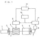
- FIG. 1 is a diagram showing the configuration of one example of a measuring apparatus to be used for carrying out the method of the present invention.
- a semiconductor laser module 1 projects, for example, a substantially parallel light 2 having a wavelength of 780 nm and an intensity of 3.0 mW.
- a polarizer 3 transmits only a light having a polarized component parallel to the plane of a sheet of paper of this instant application.
- a Faraday cell 4 sweeps the polarization direction of the substantially parallel light 2 due to the optical Faraday effect, while modulating it.
- the substantial optical path length is set to be, for example, 50 mm.
- An analyzer 6 is set so as to transmit only a light of a polarized component substantially perpendicular to the plane of a sheet of paper of this instant application.
- a photosensor 7 detects the substantially parallel light 2 transmitted through the analyzer 6.
- the apparatus has a preamplifier 8 for amplifying the output from the photosensor 7, a Faraday cell driver 9 capable of injecting a modulation signal current and a sweeping current to the Faraday cell 4, a signal generator 10 for supplying a modulation signal to the Faraday cell driver 9, and a lock-in amplifier 11 for conducting a phase sensitive detection on the output from the preamplifier 8 by using the modulation signal supplied to the Faraday cell as a reference signal.
- a preamplifier 8 for amplifying the output from the photosensor 7
- a Faraday cell driver 9 capable of injecting a modulation signal current and a sweeping current to the Faraday cell 4
- a signal generator 10 for supplying a modulation signal to the Faraday cell driver 9
- a lock-in amplifier 11 for conducting a phase sensitive detection on the output from the preamplifier 8 by using the modulation signal supplied to the Faraday cell as a reference signal.
- the output signal from the lock-in amplifier 11 is a demodulation signal, and corresponds to the "S" in the equation (9). Therefore, the output signal from the lock-in amplifier 11 shows a first-order line with respect to the sweeping current of the Faraday cell driver, in principle.
- a computer 12 records and analyzes the output from the lock-in amplifier 11, i.e., the demodulation signal, while supplying a sweeping current signal to the Faraday cell driver 9, to calculate the angle of rotation.
- a substantially parallel light 2 having a wavelength of 780 nm and an intensity of 3.0 mW was projected, and the substantial optical path length of the sample cell 5 was set to be 50 mm.
- the angles of rotation attributed to pure water and a glucose aqueous solution having a concentration of 1000 mg/dl were measured in the following manner.
- this example was carried out under such condition that the output signals from the lock-in amplifier 11, i.e., the demodulation signals became zero when an injection current into the Faraday cell was 0.0 A for the pure water, and when an injection current into the Faraday cell was 0.051 A for the glucose aqueous solution with a concentration of 1000 mg/dl, respectively. These injection currents were assumed to be standards.
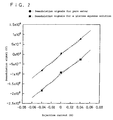
- the injection current was swept in a range from -0.06 A to 0.06 A for 60 seconds, while injecting a modulation current with an amplitude of 0.001 A and a frequency of 1.3 KHz into the Faraday cell 4.
- the relation between the injection current and the output from the lock-in amplifier 11, i.e., the demodulation signal was shown by a solid line in FIG. 2.
- the results for the pure water and for the glucose aqueous solution were indicated by the marks " ⁇ " and " ⁇ ", respectively.
- the relation between the injection current and the demodulation signal in Example 1 was shown in FIG. 2.
- the time constant of the lock-in amplifier was set as follows. In first, the time constant was set to be sufficiently shorter as compared with the sweep time, i.e., about 3 mS, which was larger than the modulation period, and the injection current was swept to obtain the relation with the demodulation signal, i.e., each solid line of FIG. 2. Then, the time constant was gradually increased to obtain the solid line of FIG. 2, during which the time constant immediately before the resulting solid line would deviate from the previously obtained solid line was confirmed.
- the term “deviate” denotes “reduce in gradient”. By performing these steps, it is possible to achieve the highest S/N ratio with respect to the length of time required for sweeping.
- the time constant was set at 100 mS.
- Each of the solid lines of FIG. 2 should be a straight line as shown by the equation (10) in principle. However, in actuality, the solid line deviates from the straight line due to the superimposition of various noises.
- the injection currents "X0" when the demodulation signals become zero read from their respective solid lines are X 0 ⁇ -0.002 (A) and X 0 ⁇ 0.05 (A) for the pure water and the glucose aqueous solution, respectively.
- the glucose aqueous solution was measured again in the following manner.
- the selected points of the injection current were set at -0.04 A, 0 A, and 0.04 A, and the same values of Y1, Y2, and Y3 as shown in Table 1 were obtained. From these values, the equation (12) was properly obtained to give C ⁇ 1.22 ⁇ 10 -2 .
- At least 3 points of the injection currents are selected to be used as criterion variables "Xi” and the demodulation signals corresponding thereto are used as dependent variables "Yi", and the linear regression treatment is performed on the basis of the principle of a least squares method to obtain a regression line. Consequently, it is possible to calculate the injection current "X 0 " which corresponds to a demodulation signal "Y" of zero, and as a result, it is possible to measure the angle of rotation with more precision.
- the sum "C” of squares of deviation is calculated by using the equation (2).
- the measurement result is judged effective. Consequently, it is possible to find out the measurement result having a large error due to influences of microparticles such as bubbles and dust, and noises.
- the measurement result with ensured reliability can be obtained.
- microparticles such as bubbles and dust are suspended, the high-reliability result to be judged effective will be obtained sometime by repeating the measurement in this manner as minimum as possible.
- the maximum number of repetitions of the remeasurement is set as a prescribed value, and the computer or the like is set such that the measurement action is stopped when the number of repetitions thereof exceeds the prescribed value.
- Such setting is practical because it can limit the measurement time. Further, it is practical because it can inhibit the possible infinite loop.
- FIG. 3 is a diagram showing the configuration of a measuring apparatus used in this example, and reference numerals 1 to 3 and 6 to 12 are the same as those in the measuring apparatus shown in FIG. 1.
- a solenoid coil was wound so that it would be possible to apply a magnetic field to the sample along the transmission direction of a substantially parallel light 2.
- the substantial optical path length was set to be 50 mm. This was for controlling the current to be flown through the solenoid coil while modulating it by the use of the optical Faraday effect of the sample, and thereby controlling the polarization direction of the substantially parallel light 2, while modulating it.
- the basic principle of the method in which the angle of rotation is measured by the Faraday effect of the sample itself in this manner is described in the specification of Laid-open Japanese Patent Publication No. Hei 09-145605.
- a modulation signal current and a control current were injected into the sample cell 13 by a Faraday cell driver 9.
- the output signal from a lock-in amplifier 11 was a demodulation signal, and corresponded to the "S" of the equation (10). Therefore, the output signal from the lock-in amplifier 11 showed a first-order line with respect to the control current of the Faraday cell driver 9 in principle.
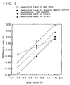
- the angles of rotation attributed to pure water, and glucose aqueous solutions with respective concentrations of 1000 mg/dl and 2000 mg/dl were measured in the following manner.
- this example was carried out under such condition that the output signals from the lock-in amplifier 11, i.e., the demodulation signals became zero, when the injection current into the solenoid coil of the sample cell was 0.02 A for the pure water, when the injection current into the solenoid coil of the sample cell was 1.01 A for the glucose aqueous solution with a concentration of 1000 mg/dl, and when the injection current into the solenoid coil of the sample cell was 2.00 A for the glucose aqueous solution with a concentration of 2000 mg/dl. These were assumed to be standards.
- the current was varied discretely to -1.5 A, 0.0 A, and 1.5 A in 1.5 A intervals for every second.
- the time constant of the lock-in amplifier was set to be 100 mS.
- the demodulation signals for the pure water, the glucose aqueous solution with a concentration of 1000 mg/dl, and the glucose aqueous solution with a concentration of 2000 mg/dl were denoted by the marks " ⁇ ", " ⁇ ", and " ⁇ ", respectively.
- the difference ⁇ X 0 between the injection current when the set demodulation signal became zero and the injection current calculated from the respective regression line expressed respectively by the equation (14), (15) or (16) was determined.
- ⁇ X 0 -0.0638 (A)
- ⁇ X 0 -0.025 (A)
- the measurement was performed again for the glucose aqueous solution with a concentration of 2000 mg/dl, of which the previous measurement result was judged ineffective.
- the measurement was performed at an injection current Xi of 0.0 (A). This was attributable to the following fact. Namely, in the state where measurement was stopped, the injection current into the solenoid coil was zero and, therefore, in consideration of the inductance thereof, a prescribed injection current could be reached in the shortest time. Measurement was performed in the same manner as described above to give a demodulation signal Yi of -0.35 (V).
- the injection current is discretely changed to at least 3 points, and these are used as criterion variables "Xi" and the demodulation signals corresponding thereto are used as dependent variables "Yi", and the linear regression treatment was performed on the basis of the principle of a least squares method to obtain a regression line. Consequently, it is possible to calculate the injection current "X 0 " which corresponds to the demodulation signal "Y" of zero, and as a result, it is possible to measure the angle of rotation with more precision.
- the correlation coefficient "R” is calculated by using the equation (4).
- the correlation coefficient "R” is not less than the prescribed minimum value, the measurement result is judged effective. Consequently, it is possible to find out the measurement result having a large error due to noises.
- the demodulation signal corresponding to at least one injection current is measured repeatedly again. This repeatedly measured value and the previously measured value are combined to calculate a regression line again, and also calculate a correlation coefficient "R” again. If the correlation coefficient "R" is not less than the prescribed minimum value, the measurement result is judged effective. Thus, by repeatedly performing the measurement, it is possible to obtain an effective measurement result with efficiency. Further, the value of " ⁇ " (corresponding to the injection current) is not required to be changed continuously so that "S" becomes zero as in the prior art, resulting in a simplified configuration of a circuit.
- the injection current "X0" when the demodulation signal "Y" becomes zero is calculated by extrapolation from the regression line. Therefore, it is not necessary to actually inject such a current which enables the demodulation signal to become 0. Accordingly, it is possible to set large the measurable concentration range of the sample.
- Example 1 the overall time taken to sweep the injection current is required to be sufficiently longer as compared with the time constant of the lock-in amplifier. Therefore, a longer measurement time than that in this example is required for ensuring an S/N ratio comparable to that in this example.
- the period of time from the start of injecting the injection current at each discrete measuring point to the determination of the demodulation signal may be set to be (7 to 8 times) larger than the time constant of the lock-in amplifier, so that the measurement time can be shorten.
- the injection current was discretely set at two points "X1" and "X2". These "X1” and “X2” and the demodulation signals “Y1” and “Y2” respectively corresponding thereto were used to calculate a line. It was possible to calculate the injection current "X 0 " when the demodulation signal "Y” became zero from this line. Consequently, it was possible to measure the angle of rotation with high precision.
- the measuring apparatus shown in FIG. 3 was used in this example.
- this example was carried out under such condition that the output signals from the lock-in amplifier 11, i.e., the demodulation signals became zero, when the injection current into the solenoid coil of the sample cell was 0.02 A for the pure water, when the injection current into the solenoid coil of the sample cell was 1.01 A for a glucose aqueous solution with a concentration of 1000 mg/dl, and when the injection current into the solenoid coil of the sample cell was 2.00 A for a glucose aqueous solution with a concentration of 2000 mg/dl. These were assumed to be standards.
- Example 2 In the same manner as in Example 2, a modulation current having an amplitude of 0.001 (A) and a frequency of 1.3 KHz was injected into the solenoid coil 13.
- the injection current was set at -1.5 (A), then varied discretely to 1.5 A at an elapse of one second therefrom. Then, another one second was allowed to elapse.
- the time constant of the lock-in amplifier was set to be 100 mS.
- the measured values when the glucose aqueous solution with a concentration of 1000 mg/dl was measured are shown in Table 4.
- the demodulation signal at the same injection current as that in the first measurement was used as a measured value in repeatedly performing the measurement again. Namely, the measurement was performed again for at least one value of "Xi" (injection current) out of the values of "Xi" in the first measurement.
- the measurement is performed at the time when the injection current Xi is 0.0 (A).
- the injection current into the solenoid coil is zero. Therefore, in consideration of the inductance thereof, a prescribed injection current can be reached in the shortest time. This is advantageous for shortening the measurement time. Further, when a malfunction invariably occurring with respect to the same injection current and the like cause the noises, it may be possible to avoid the ineffective measurement by performing the measurement with a different injection current from that in the first measurement in this manner.
- the injection currents "X 0 " when the demodulation signals became zero were calculated from their respective regression lines to give X 0 ⁇ 0.499 (A) and X 0 ⁇ 0.604 (A) for the urines 1 and 2, respectively. These denoted angles of rotation, and from these, the glucose concentrations "Co” were calculated by the following equation (22): where X 0 (GLO) denotes an injection current set so that a demodulation signal for pure water becomes zero, and X 0 (GL1000) denotes an injection current set so that a demodulation signal for the glucose aqueous solution with a concentration of 1000 mg/dl becomes zero, to give the glucose concentrations of the urines, i.e., the urine sugar value UG1 ⁇ 484 (mg/dl) and the urine sugar value UG2 ⁇ 590 (mg/dl). These values indicated that it was possible to perform the measurement with higher precision for the urine 1.
- Table 7 indicates that the urine 1 has an "R” closer to 1, and provides higher precision than the urine 2.
- the measurement was performed for a glucose aqueous solution with a concentration of 2000 mg/dl by using the measuring apparatus shown in FIG. 3, and under the same conditions as in Example 2.
- large suspending particles entered the optical path at an injection current of 1.5 A, so that the transmitted light became substantially zero and the demodulation signal also became zero.
- Table 8 Injection current Xi(A) Demodulation signal for glucose aqueous solution Yi(V) Conc. 2000(mg/dl) -1.5 -0.700 0.0 -0.320 1.5 -0.00
- the configuration of a circuit is simplified, the measurement time is constant, and the precision of the measurement result can be found.
- the precision of the measurement result can be found.
- a method of polarimetry characterized by calculating an angle of rotation from discrete 2 or 3 measuring points, and performing again the measurement on the measuring point which is not effective.
Landscapes
- General Health & Medical Sciences (AREA)
- Health & Medical Sciences (AREA)
- Life Sciences & Earth Sciences (AREA)
- Chemical & Material Sciences (AREA)
- Analytical Chemistry (AREA)
- Biochemistry (AREA)
- Physics & Mathematics (AREA)
- General Physics & Mathematics (AREA)
- Immunology (AREA)
- Pathology (AREA)
- Investigating Or Analysing Materials By Optical Means (AREA)
- Investigating Or Analysing Biological Materials (AREA)
- Length Measuring Devices By Optical Means (AREA)
Applications Claiming Priority (2)
| Application Number | Priority Date | Filing Date | Title |
|---|---|---|---|
| JP2000323885 | 2000-10-24 | ||
| JP2000323885A JP2002131223A (ja) | 2000-10-24 | 2000-10-24 | 旋光度計測方法およびそれを用いた尿検査方法 |
Publications (2)
| Publication Number | Publication Date |
|---|---|
| EP1202044A2 true EP1202044A2 (de) | 2002-05-02 |
| EP1202044A3 EP1202044A3 (de) | 2004-07-28 |
Family
ID=18801495
Family Applications (1)
| Application Number | Title | Priority Date | Filing Date |
|---|---|---|---|
| EP01125160A Withdrawn EP1202044A3 (de) | 2000-10-24 | 2001-10-23 | Polarimetrieverfahren |
Country Status (3)
| Country | Link |
|---|---|
| US (1) | US6934023B2 (de) |
| EP (1) | EP1202044A3 (de) |
| JP (1) | JP2002131223A (de) |
Families Citing this family (2)
| Publication number | Priority date | Publication date | Assignee | Title |
|---|---|---|---|---|
| US20110149282A1 (en) * | 2009-12-18 | 2011-06-23 | Rudolph Research Analytical | Polarimeter and Polarimetry Method |
| US10126172B1 (en) * | 2017-10-16 | 2018-11-13 | King Fahd University Of Petroleum And Minerals | Faraday rotator device |
Family Cites Families (15)
| Publication number | Priority date | Publication date | Assignee | Title |
|---|---|---|---|---|
| US3312141A (en) | 1962-04-23 | 1967-04-04 | Applied Physics Corp | System for measuring optical activity of materials |
| JPS6312984A (ja) | 1986-07-03 | 1988-01-20 | Toshiba Corp | 目標検出追尾装置 |
| JPH07119768B2 (ja) * | 1986-07-04 | 1995-12-20 | 株式会社日立製作所 | デイスクリート自動分析方法 |
| EP0351659B1 (de) * | 1988-07-19 | 1993-02-10 | Siemens Aktiengesellschaft | Verfahren zur Messung der Konzentration optisch aktiver Substanzen und Anordnung zur Durchführung des Verfahrens |
| JPH06102175A (ja) * | 1992-09-18 | 1994-04-15 | Hitachi Ltd | 原子吸光光度計 |
| JP3322282B2 (ja) * | 1993-05-13 | 2002-09-09 | 和光純薬工業株式会社 | エンドトキシン測定装置 |
| JP3072040B2 (ja) * | 1995-11-29 | 2000-07-31 | 松下電器産業株式会社 | 旋光度測定方法、旋光計、尿検査方法及び尿検査装置 |
| WO1997018470A1 (en) | 1995-11-16 | 1997-05-22 | Matsushita Electric Industrial Co., Ltd. | Method and apparatus for urinalysis, method of measuring optical rotation and polarimeter |
| JP3308173B2 (ja) | 1996-11-07 | 2002-07-29 | 松下電器産業株式会社 | 尿検査方法およびそれに用いる尿検査装置 |
| TW407201B (en) | 1997-09-09 | 2000-10-01 | Matsushita Electric Industrial Co Ltd | Sample cell for polarimetry, polarimeter, and polarimetry |
| US5999672A (en) | 1997-12-13 | 1999-12-07 | Light Chip, Inc. | Integrated bi-directional dual axial gradient refractive index/diffraction grating wavelength division multiplexer |
| JP3415034B2 (ja) * | 1998-07-31 | 2003-06-09 | 松下電器産業株式会社 | 旋光度測定方法、濃度判定方法および濃度制御方法並びに旋光計 |
| US6269203B1 (en) | 1999-03-17 | 2001-07-31 | Radiant Photonics | Holographic optical devices for transmission of optical signals |
| US6620622B1 (en) * | 1999-06-29 | 2003-09-16 | Matsushita Electric Industrial Co., Ltd. | Method of polarimetry and method of urinalysis using the same |
| US6978062B2 (en) | 2001-02-21 | 2005-12-20 | Ibsen Photonics A/S | Wavelength division multiplexed device |
-
2000
- 2000-10-24 JP JP2000323885A patent/JP2002131223A/ja active Pending
-
2001
- 2001-10-19 US US09/982,159 patent/US6934023B2/en not_active Expired - Lifetime
- 2001-10-23 EP EP01125160A patent/EP1202044A3/de not_active Withdrawn
Also Published As
| Publication number | Publication date |
|---|---|
| US20020075480A1 (en) | 2002-06-20 |
| EP1202044A3 (de) | 2004-07-28 |
| JP2002131223A (ja) | 2002-05-09 |
| US6934023B2 (en) | 2005-08-23 |
Similar Documents
| Publication | Publication Date | Title |
|---|---|---|
| EP0805352B1 (de) | Verfahren und vorrichtung zur urinanalyse, verfahren zur messung optischer rotation und polarimeter | |
| US7282367B2 (en) | Method for verifying amount of sample solution, method for controlling measurement system and method for measuring concentration of solution in apparatus for measuring optical characteristic | |
| US6620622B1 (en) | Method of polarimetry and method of urinalysis using the same | |
| CN113758877B (zh) | 一种频域量子弱测量生物分子传感器及其测量方法 | |
| EP1113270B1 (de) | Verfahren zur Messung einer Proteinkonzentration | |
| EP0902270B1 (de) | Polarimetrische Probenzelle und Polarimeter | |
| US6643021B1 (en) | Method for controlling optical property measurement system | |
| EP1096248A2 (de) | Verfahren und Vorrichtung zur Messung der Konzentration einer Lösung | |
| JP3072040B2 (ja) | 旋光度測定方法、旋光計、尿検査方法及び尿検査装置 | |
| EP1598656A2 (de) | Verfahren und Vorrichtung zum Zuführen einer Flüssigkeitsprobe in eine optische Küvette, sowie deren Verwendung in einem Polarimeter | |
| EP1202044A2 (de) | Polarimetrieverfahren | |
| WO1999030132A1 (en) | Angle-of-rotation measuring instrument urine analysis method | |
| JP3350877B2 (ja) | 旋光度測定方法、濃度測定方法 | |
| JP3694449B2 (ja) | 溶液濃度計測方法および溶液濃度計測装置 | |
| JP2002131223A5 (de) | ||
| JP3393997B2 (ja) | 液体の光学特性計測装置における計測系制御方法 | |
| JP2005189245A (ja) | 溶液濃度計測方法および溶液濃度計測装置 | |
| EP1111368A1 (de) | Verfahren zur Lösungskonzentrationsmessung und Harnanalyseverfahren zur dessen Verwendung | |
| JPH08128946A (ja) | 光学特性測定方法及び測定装置 | |
| JP2004279250A (ja) | 濃度測定装置 | |
| JPH1194732A (ja) | サンプルセル及びこれを用いた旋光計、尿検査装置 | |
| SU1194144A1 (ru) | Способ определения свойств оптически активных объектов и устройство для его осуществления | |
| SU1749782A1 (ru) | Способ определени времени установлени равновесного состо ни адсорбированного сло молекул на поверхности полупроводниковых материалов | |
| US8529837B2 (en) | System and method for detecting specific binding reactions using magnetic labels | |
| JPH1183729A (ja) | サンプルセル及びこれを用いた旋光計、尿検査装置 |
Legal Events
| Date | Code | Title | Description |
|---|---|---|---|
| PUAI | Public reference made under article 153(3) epc to a published international application that has entered the european phase |
Free format text: ORIGINAL CODE: 0009012 |
|
| AK | Designated contracting states |
Kind code of ref document: A2 Designated state(s): AT BE CH CY DE DK ES FI FR GB GR IE IT LI LU MC NL PT SE TR |
|
| AX | Request for extension of the european patent |
Free format text: AL;LT;LV;MK;RO;SI |
|
| PUAL | Search report despatched |
Free format text: ORIGINAL CODE: 0009013 |
|
| AK | Designated contracting states |
Kind code of ref document: A3 Designated state(s): AT BE CH CY DE DK ES FI FR GB GR IE IT LI LU MC NL PT SE TR |
|
| AX | Request for extension of the european patent |
Extension state: AL LT LV MK RO SI |
|
| 17P | Request for examination filed |
Effective date: 20041104 |
|
| AKX | Designation fees paid |
Designated state(s): DE FR GB |
|
| STAA | Information on the status of an ep patent application or granted ep patent |
Free format text: STATUS: THE APPLICATION HAS BEEN WITHDRAWN |
|
| 18W | Application withdrawn |
Effective date: 20051228 |