EP1202086A1 - Fibre optique - Google Patents
Fibre optique Download PDFInfo
- Publication number
- EP1202086A1 EP1202086A1 EP01124228A EP01124228A EP1202086A1 EP 1202086 A1 EP1202086 A1 EP 1202086A1 EP 01124228 A EP01124228 A EP 01124228A EP 01124228 A EP01124228 A EP 01124228A EP 1202086 A1 EP1202086 A1 EP 1202086A1
- Authority
- EP
- European Patent Office
- Prior art keywords
- wavelength
- core
- optical fiber
- refractive index
- cladding
- Prior art date
- Legal status (The legal status is an assumption and is not a legal conclusion. Google has not performed a legal analysis and makes no representation as to the accuracy of the status listed.)
- Withdrawn
Links
- 239000013307 optical fiber Substances 0.000 title claims abstract description 118
- 230000005540 biological transmission Effects 0.000 claims abstract description 101
- 239000006185 dispersion Substances 0.000 claims abstract description 48
- 238000005253 cladding Methods 0.000 claims description 119
- 229910052739 hydrogen Inorganic materials 0.000 claims description 85
- 239000001257 hydrogen Substances 0.000 claims description 85
- UFHFLCQGNIYNRP-UHFFFAOYSA-N Hydrogen Chemical compound [H][H] UFHFLCQGNIYNRP-UHFFFAOYSA-N 0.000 claims description 83
- 230000032683 aging Effects 0.000 claims description 63
- 230000003287 optical effect Effects 0.000 claims description 54
- 239000000835 fiber Substances 0.000 description 39
- 239000010410 layer Substances 0.000 description 6
- 230000002093 peripheral effect Effects 0.000 description 6
- 238000000034 method Methods 0.000 description 5
- YBMRDBCBODYGJE-UHFFFAOYSA-N germanium dioxide Chemical compound O=[Ge]=O YBMRDBCBODYGJE-UHFFFAOYSA-N 0.000 description 4
- 239000000463 material Substances 0.000 description 4
- 238000005452 bending Methods 0.000 description 3
- 239000011347 resin Substances 0.000 description 3
- 229920005989 resin Polymers 0.000 description 3
- VYPSYNLAJGMNEJ-UHFFFAOYSA-N Silicium dioxide Chemical compound O=[Si]=O VYPSYNLAJGMNEJ-UHFFFAOYSA-N 0.000 description 2
- 239000011247 coating layer Substances 0.000 description 2
- 238000007599 discharging Methods 0.000 description 2
- 239000011521 glass Substances 0.000 description 2
- 238000000227 grinding Methods 0.000 description 2
- 150000002431 hydrogen Chemical class 0.000 description 2
- 238000012986 modification Methods 0.000 description 2
- 230000004048 modification Effects 0.000 description 2
- 239000011248 coating agent Substances 0.000 description 1
- 238000000576 coating method Methods 0.000 description 1
- 239000000470 constituent Substances 0.000 description 1
- 238000007796 conventional method Methods 0.000 description 1
- 230000007547 defect Effects 0.000 description 1
- 230000002349 favourable effect Effects 0.000 description 1
- 239000005373 porous glass Substances 0.000 description 1
- 238000002360 preparation method Methods 0.000 description 1
- 238000005245 sintering Methods 0.000 description 1
Images



Classifications
-
- G—PHYSICS
- G02—OPTICS
- G02B—OPTICAL ELEMENTS, SYSTEMS OR APPARATUS
- G02B6/00—Light guides; Structural details of arrangements comprising light guides and other optical elements, e.g. couplings
- G02B6/02—Optical fibres with cladding with or without a coating
- G02B6/02214—Optical fibres with cladding with or without a coating tailored to obtain the desired dispersion, e.g. dispersion shifted, dispersion flattened
- G02B6/02219—Characterised by the wavelength dispersion properties in the silica low loss window around 1550 nm, i.e. S, C, L and U bands from 1460-1675 nm
- G02B6/02228—Dispersion flattened fibres, i.e. having a low dispersion variation over an extended wavelength range
- G02B6/02238—Low dispersion slope fibres
- G02B6/02242—Low dispersion slope fibres having a dispersion slope <0.06 ps/km/nm2
-
- C—CHEMISTRY; METALLURGY
- C03—GLASS; MINERAL OR SLAG WOOL
- C03B—MANUFACTURE, SHAPING, OR SUPPLEMENTARY PROCESSES
- C03B37/00—Manufacture or treatment of flakes, fibres, or filaments from softened glass, minerals, or slags
- C03B37/01—Manufacture of glass fibres or filaments
- C03B37/012—Manufacture of preforms for drawing fibres or filaments
- C03B37/01205—Manufacture of preforms for drawing fibres or filaments starting from tubes, rods, fibres or filaments
- C03B37/01225—Means for changing or stabilising the shape, e.g. diameter, of tubes or rods in general, e.g. collapsing
- C03B37/01228—Removal of preform material
-
- C—CHEMISTRY; METALLURGY
- C03—GLASS; MINERAL OR SLAG WOOL
- C03B—MANUFACTURE, SHAPING, OR SUPPLEMENTARY PROCESSES
- C03B37/00—Manufacture or treatment of flakes, fibres, or filaments from softened glass, minerals, or slags
- C03B37/01—Manufacture of glass fibres or filaments
- C03B37/012—Manufacture of preforms for drawing fibres or filaments
- C03B37/014—Manufacture of preforms for drawing fibres or filaments made entirely or partially by chemical means, e.g. vapour phase deposition of bulk porous glass either by outside vapour deposition [OVD], or by outside vapour phase oxidation [OVPO] or by vapour axial deposition [VAD]
- C03B37/01446—Thermal after-treatment of preforms, e.g. dehydrating, consolidating, sintering
-
- C—CHEMISTRY; METALLURGY
- C03—GLASS; MINERAL OR SLAG WOOL
- C03B—MANUFACTURE, SHAPING, OR SUPPLEMENTARY PROCESSES
- C03B37/00—Manufacture or treatment of flakes, fibres, or filaments from softened glass, minerals, or slags
- C03B37/01—Manufacture of glass fibres or filaments
- C03B37/012—Manufacture of preforms for drawing fibres or filaments
- C03B37/014—Manufacture of preforms for drawing fibres or filaments made entirely or partially by chemical means, e.g. vapour phase deposition of bulk porous glass either by outside vapour deposition [OVD], or by outside vapour phase oxidation [OVPO] or by vapour axial deposition [VAD]
- C03B37/01466—Means for changing or stabilising the diameter or form of tubes or rods
-
- C—CHEMISTRY; METALLURGY
- C03—GLASS; MINERAL OR SLAG WOOL
- C03C—CHEMICAL COMPOSITION OF GLASSES, GLAZES OR VITREOUS ENAMELS; SURFACE TREATMENT OF GLASS; SURFACE TREATMENT OF FIBRES OR FILAMENTS MADE FROM GLASS, MINERALS OR SLAGS; JOINING GLASS TO GLASS OR OTHER MATERIALS
- C03C25/00—Surface treatment of fibres or filaments made from glass, minerals or slags
-
- C—CHEMISTRY; METALLURGY
- C03—GLASS; MINERAL OR SLAG WOOL
- C03C—CHEMICAL COMPOSITION OF GLASSES, GLAZES OR VITREOUS ENAMELS; SURFACE TREATMENT OF GLASS; SURFACE TREATMENT OF FIBRES OR FILAMENTS MADE FROM GLASS, MINERALS OR SLAGS; JOINING GLASS TO GLASS OR OTHER MATERIALS
- C03C25/00—Surface treatment of fibres or filaments made from glass, minerals or slags
- C03C25/60—Surface treatment of fibres or filaments made from glass, minerals or slags by diffusing ions or metals into the surface
- C03C25/607—Surface treatment of fibres or filaments made from glass, minerals or slags by diffusing ions or metals into the surface in the gaseous phase
-
- G—PHYSICS
- G02—OPTICS
- G02B—OPTICAL ELEMENTS, SYSTEMS OR APPARATUS
- G02B6/00—Light guides; Structural details of arrangements comprising light guides and other optical elements, e.g. couplings
- G02B6/02—Optical fibres with cladding with or without a coating
- G02B6/036—Optical fibres with cladding with or without a coating core or cladding comprising multiple layers
- G02B6/03616—Optical fibres characterised both by the number of different refractive index layers around the central core segment, i.e. around the innermost high index core layer, and their relative refractive index difference
- G02B6/03622—Optical fibres characterised both by the number of different refractive index layers around the central core segment, i.e. around the innermost high index core layer, and their relative refractive index difference having 2 layers only
- G02B6/03633—Optical fibres characterised both by the number of different refractive index layers around the central core segment, i.e. around the innermost high index core layer, and their relative refractive index difference having 2 layers only arranged - -
-
- C—CHEMISTRY; METALLURGY
- C03—GLASS; MINERAL OR SLAG WOOL
- C03B—MANUFACTURE, SHAPING, OR SUPPLEMENTARY PROCESSES
- C03B2203/00—Fibre product details, e.g. structure, shape
- C03B2203/10—Internal structure or shape details
- C03B2203/22—Radial profile of refractive index, composition or softening point
- C03B2203/29—Segmented core fibres
-
- C—CHEMISTRY; METALLURGY
- C03—GLASS; MINERAL OR SLAG WOOL
- C03B—MANUFACTURE, SHAPING, OR SUPPLEMENTARY PROCESSES
- C03B2203/00—Fibre product details, e.g. structure, shape
- C03B2203/36—Dispersion modified fibres, e.g. wavelength or polarisation shifted, flattened or compensating fibres (DSF, DFF, DCF)
-
- G—PHYSICS
- G02—OPTICS
- G02B—OPTICAL ELEMENTS, SYSTEMS OR APPARATUS
- G02B6/00—Light guides; Structural details of arrangements comprising light guides and other optical elements, e.g. couplings
- G02B6/02—Optical fibres with cladding with or without a coating
- G02B6/02004—Optical fibres with cladding with or without a coating characterised by the core effective area or mode field radius
- G02B6/02009—Large effective area or mode field radius, e.g. to reduce nonlinear effects in single mode fibres
Definitions
- the present invention relates to an optical fiber suitable as a transmission line of a wavelength division multiplexing (WDM) transmission system for transmitting multiplexed signals of a plurality of channels having wavelengths different from each other.
- WDM wavelength division multiplexing
- a wavelength division multiplexing (WDM) transmission system is a system for transmitting multiplexed signals (WDM signals) of a plurality of channels included in a predetermined signal wavelength band, and makes it possible to transmit and receive a large capacity of information.
- WDM signals multiplexed signals
- signal wavelength bands in which WDM transmissions are carried out have been in the wavelength range of 1530 nm to 1565 nm, and optical fibers employed in a transmission line have been designed so as to have an optimal characteristic in this wavelength range (e.g., U.S. Patent No. 5,327,516).
- the wavelength range of 1565 nm to 1625 nm, which is on the longer wavelength side than the above-mentioned wavelength range, and the wavelength range of 1440 nm to 1530 nm, which is on the shorter wavelength side than the above-mentioned wavelength range, have been under consideration as a signal wavelength band in which WDM transmissions are to be carried out, whereby optical fibers having favorable characteristics in these wavelength ranges have been proposed as well.
- the conventional optical fibers developed or proposed heretofore have a chromatic dispersion not suitable for WDM transmission in wavelength ranges having awavelength of 1440 nm or shorter.
- the conventional optical fibers have a zero-dispersion wavelength at a wavelength of 1450 nm or longer, and their chromatic dispersion in the wavelength range of 1300 nm to 1625 nm does not have a fixed polarity, thereby failing to realize WDM transmissions using the whole wavelength range as a signal wavelength band.
- the conventional optical fibers While having a chromatic dispersion of several ps/nm/km enabling WDM transmissions at a certain wavelength, the conventional optical fibers have a chromatic dispersion of several tens of ps/nm/km unsuitable for WDM transmissions at other wavelengths, thus making it difficult to realize WDM transmissions using the whole wavelength range of 1300 nm to 1625 nm as a signal wavelength band. Further, since the transmission loss at a wavelength of 1383 nm increases when hydrogen existing in the environment of use and hydrogen occurring from materials constituting optical cables combines with glass defects, it has been hard for the conventional optical fibers to realize WDM transmissions using wavelength ranges with a wavelength of 1440 nm or shorter as a signal wavelength band.
- an object of the present invention to provide an optical fiber suitable as a transmission line for WDM transmissions using the whole wavelength range of 1300 nm to 1625 nm as a signal light wavelength band.
- the optical fiber according to the present invention has a cutoff wavelength of 1300 nm or less at a length of 22m, a transmission loss of 0.4 dB/km or less at a wavelength of 1383 nm, a chromatic dispersion of 0.1 ps/nm/km or more but 5.5 ps/nm/km or less at a wavelength of 1383 nm, and a dispersion slope having an absolute value of 0.1 ps/nm 2 /km or less in the wavelength range of 1300 nm to 1625 nm.
- this optical fiber is suitable as a transmission line realizing WDM transmissions using the whole wavelength range of 1300 nm to 1625 nm as a signal wavelength band.
- the transmission loss at a wavelength of 1550 nm is 0.3 dB/kmor less
- the chromatic dispersion in the wavelength range of 1530 nm to 1565 nm is 0.1 ps/nm/km or more but 16.5 ps/nm/km or less.
- the optical fiber secures a transmission quality on a par with or better than that of conventional WDM optical fibers in the wavelength band of 1530 nm to 1565 nm, which is mainly used for WDM transmissions.
- the transmission loss at a wavelength of 1383 nm after completing a hydrogen aging process in which hydrogen is let out for 14 days or more after aging for 4 days in an atmosphere with a hydrogen pressure of 1 atm at room temperature (25°C) is 0.4 dB/km or less, or does not exceed the transmission loss at a wavelength of 1310 nm exhibited before the hydrogen aging process.
- the transmission loss at a wavelength of 1383 nm after completing a hydrogen aging process in which hydrogen is let out for 14 days or more after aging for 10 days in the atmosphere with a hydrogen pressure of 0.01 atm at room temperature (25°C) is 0.4 dB/km or less, or does not exceed the transmission loss at a wavelength of 1300 nm exhibited before the hydrogen aging process.
- the optical fiber is less likely to be influenced by hydrogen existing in the environment of use or hydrogen generated from materials constituting optical cables, so that the transmission loss at a wavelength of 1383 nm increases only slightly (0.4 dB/km or less), whereby the optical fiber is also suitable for WDM transmissions using wavelength ranges with a wavelength of 1440 nm or shorter as a signal wavelength band.
- the optical fiber according to the present invention comprises a first core extending along a predetermined axis and having a first refractive index; a second core, provided on the outer periphery of the first core, having a second refractive index lower than the first refractive index; and a cladding region, provided on the outer periphery of the second core, having a third refractive index lower than the second refractive index.
- the cladding region includes an optical cladding and a physical cladding.
- the ratio (c/a) of the outer diameter 2c of the optical cladding to the outer diameter 2a of the first core is 4.8 or more.
- the optical cladding whose OH radical content is smaller than that in the physical cladding acting as a jacket layer is made thicker, whereby the transmission loss of the optical fiber at a wavelength of 1383 nm is effectively reduced.
- the optical cladding refers to the inner area of cladding region functioning as a waveguide through which light propagates
- the physical cladding refers to the outer area of cladding region, which is also referred to as the jacket layer and positioned on the outside of the optical cladding, imparting a physical strength to the optical fiber.
- the method of calculating the outer diameter of the optical cladding is disclosed in U.S. Patent No. 5,740,297.
- a core rod including an area to become the first core, second core, and optical cladding in the optical fiber preform is dehydrated at a high temperature of 1250°C or more.
- the high-temperature dehydrating process eliminates OH radical from the core rod, whereby the transmission loss of the optical fiber at a wavelength of 1383 nm is reduced.
- the core rod has an outer peripheral part ground by a thickness of 5% or more with respect to the outer diameter thereof. When the outer peripheral part of core rod having a relatively large residual amount of OH radical is ground as such, the transmission loss of the optical fiber at a wavelength of 1383 nm is reduced.
- the optical fiber according to the present invention has a structure suitable as a transmission line for WDM transmissions using the whole wavelength range of 1300 nm to 1625 nm as a signal wavelength band.
- Fig. 1 is a graph showing the wavelength dependence of transmission loss in the optical fiber according to the present invention.
- the transmission loss of the optical fiber according to the present invention is 0.4 dB/km or less at a wavelength of 1383 nm.
- the transmission loss of the optical fiber is 0.3 dB/km or less at a wavelength of 1550 nm, and 0.4 dB/km or less at a wavelength of 1310 nm.
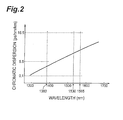
- Fig. 2 is a graph showing the wavelength dependence of chromatic dispersion in the optical fiber according to the present invention.
- the chromatic dispersion of the optical fiber according to the present invention is 0.1 ps/nm/km or more but 5.5 ps/nm/km or less at a wavelength of 1383 nm.
- the chromatic dispersion of the optical fiber is 0.1 ps/nm/km or more but 16.5 ps/nm/km or less in the wavelength range of 1530 nm to 1565 nm.
- the optical fiber according to the present invention has a cutoff wavelength of 1300 nm or less at a length of 22 m and a dispersion slope with an absolute value of 0.1 ps/nm 2 /km or less in the wavelength range of 1300 nm to 1625 nm.
- the bending loss of the optical fiber at a wavelength of 1550 nm is 0.05 dB or less when wound by 100 turns about a mandrel having a diameter of 75 mm, and 0.5 dB or less when wound by 1 turn about a mandrel having a diameter of 30 mm.
- Fig. 3A is a view showing a cross-sectional structure of the optical fiber according to the present invention.
- the optical fiber 1 according to the present invention comprises a core region 100 and a cladding region 200 surrounding the core region 100.
- the core region 100 comprises a first core 101 extending along a predetermined axis and having a first refractive index n 1 and an outer diameter 2a; and a second core 102 surrounding the first core 101 and having a second refractive index n 2 lower than the first refractive index n 1 and an outer diameter 2b.
- the cladding region 200 has an optical cladding 201 surrounding the second core 102 and a physical cladding 202 surrounding the optical cladding.
- each of the optical cladding 201 and physical cladding 202 has a third refractive index n 3 which is lower than the second refractive index n 2 , whereas the optical cladding 201 has an outer diameter 2c. It is not always necessary for the refractive index of the optical cladding 201 and that of the physical cladding 202 to coincide with each other.
- the optical cladding refers to the inner area of cladding region functioning as a waveguide through which light propagates; whereas the physical cladding refers to the outer area of cladding, which is also known as a jacket layer and positioned on the outside of the optical cladding, imparting a physical strength to the optical fiber.
- the method of calculating the outer diameter of the optical cladding is disclosed in U.S. Patent No. 5,740,297.
- Fig. 3B shows a refractive index profile 150 showing the refractive index in each part on a line L in Fig. 3A. Areas 151, 152, 153, and 154 in the refractive index profile 150 indicate the refractive indices of individual parts on the line L of the first core 101, second core 102, optical cladding 201, and physical cladding 202, respectively.
- the optical fiber 1 having such a refractive index profile 150 is obtained when, while using silica glass as a base, the first core 101 and second core 102 are doped with their respective appropriate amounts of GeO 2 , or when the first core 101 and the cladding region 200 are doped with GeO 2 and F element, respectively.
- a core rod including areas to become the first core 101, second core 102, and optical cladding 201 in the optical fiber preform is obtained by way of the preparation of a porous glass rod including these areas and the transparentization by sintering.
- the glass pipe and core rod are collapsed, whereby the optical fiber preform is obtained.
- ⁇ n 1 is the relative refractive index difference of the first core 101 with reference to the refractive index n 3 of the cladding region 200, and is given by the following expression (1):
- ⁇ n 2 is the relative refractive index difference of the second core 102 with reference to the refractive index n 3 of the cladding region 200, and is given by the following expression (2):
- ⁇ n 1 and ⁇ n 2 are each given with reference to the refractive index of the cladding region 200, they will be given with reference to the refractive index of the physical cladding 202 if the refractive index of the optical cladding 201 and that of the physical cladding 202 do not coincide with each other.
- cladding region refers to the whole area including both of the optical cladding 201 and physical cladding 202.
- the ratio (c/a) of the outer diameter 2c of the optical cladding 201 to the outer diameter 2a of the first core 101 be 4.8 or more.
- the optical cladding 201 whose OH radical content is smaller than that in the physical cladding 202 provided on the outermost layer of the optical fiber 1 as a jacket layer can be made thicker, whereby the transmission loss of the optical fiber 1 at a wavelength of 1383 nm can be reduced.
- the core rod including areas to become the first core 101, second core 102, and optical cladding 201 be dehydrated at a high temperature of 1250°C or more.
- OH radical is eliminated by the high-temperature dehydrating processing, whereby the transmission loss of the optical fiber 1 at a wavelength of 1383 nm is lowered.
- the outer peripheral part of core rod including the areas to become the first core 101, second core 102, and optical cladding 201 be ground by a thickness of 5% or more of the outer diameter of the core rod.
- the optical fiber 1 For reducing the transmission loss of the optical fiber 1 at a wavelength of 1383 nm, it is preferred to carry out at least two processes of setting the ratio (c/a) of the outer diameter 2c of the optical cladding 201 to the outer diameter 2a of the first core 101 to 4.8 or more, dehydrating the core rod at a high temperature of 1250°C or more in the step of making the optical fiber preform, and grinding the outer peripheral part of the core rod by a thickness of 5% or more of the diameter of the core rod.
- the mode field diameter at a wavelength of 1550 nm is 8.7 ⁇ m or more
- each of the amounts of concentricity error of the first core 101 and second core 102 with respect to the cladding region 200, i.e., the core concentricity error is 0.5 ⁇ m or less
- the outer diameter of the cladding region 200, i.e., the cladding diameter is 124.0 ⁇ m to 126.0 ⁇ m
- the non-circularity of the outer diameter of the cladding region 200, i.e., the cladding non-circularity is 1% or less
- the outer diameter of the resin layer covering the optical fiber 1, i.e., the coating diameter is 235 ⁇ m to 265 ⁇ m
- the proof level is 0.86 GPa (1.2%).
- the above-mentioned core concentricity error and cladding non-circularity are numerical values obtained according to the calculating methods
- the outer diameter 2a of the first core is 6.3 ⁇ m
- the outer diameter 2b of the second core is 37.7 ⁇ m
- the outer diameter of the whole cladding region (corresponding to the outer diameter of the physical cladding and the fiber outer diameter) is 125.2 ⁇ m
- the outer diameter of the resin coating layer is 254 ⁇ m.
- the relative refractive index differences ⁇ n 1 and ⁇ n 2 of the first and second cores with reference to the cladding region are 0.49% and 0.079%, respectively.
- the transmission loss was 0.32 dB/km at a wavelength of 1310 nm, 0.27 dB/km at a wavelength of 1383 nm, and 0.20 dB/km at a wavelength of 1550 nm.
- Its chromatic dispersion was 1.3 ps/nm/km at a wavelength of 1383 nm, and 11.9 ps/nm/km at a wavelength of 1550 nm.
- Its cutoff wavelength at a length of 22 m was 1227 nm or less.
- Its absolute value of dispersion slope at a wavelength of 1550 nm was 0.063 ps/nm 2 /km or less.
- Its bending loss at a wavelength of 1550 nm was 0.05 dB or less when wound by 100 turns about a mandrel having a diameter of 75 mm, and 0.5 dB or less when wound by 1 turn about a mandrel having a diameter of 30 mm.
- Its mode field diameter at a wavelength of 1550 nm was 9.3 ⁇ m, the core concentricity error was 0.1 ⁇ m or less, and the cladding non-circularity was 0.2% or less. Its proof level was 0.86 GPa (1.2%).
- the outer diameter 2a of the first core is 7.4 ⁇ m
- the outer diameter 2b of the second core is 48.1 ⁇ m
- the outer diameter of the whole cladding region (corresponding to the outer diameter of the physical cladding and the fiber outer diameter) is 125.1 ⁇ m
- the outer diameter of the resin coating layer is 252 ⁇ m.
- the relative refractive index differences ⁇ n 1 and ⁇ n 2 of the first and second cores with reference to the cladding region are 0.47% and 0.058%, respectively.
- the transmission loss was 0.33 dB/km at a wavelength of 1310 nm, 0.28 dB/km at a wavelength of 1383 nm, and 0.19 dB/km at a wavelength of 1550 nm.
- Its chromatic dispersion was 5.0 ps/nm/km at a wavelength of 1383 nm, and 15.8 ps/nm/km at a wavelength of 1550 nm.
- Its cutoff wavelength at a length of 22 m was 1267 nm or less.
- Its absolute value of dispersion slope at a wavelength of 1550 nm was 0.064 ps/nm 2 /km or less.
- Its bending loss at a wavelength of 1550 nm was 0.05 dB or less when wound by 100 turns about a mandrel having a diameter of 75 mm, and 0.5 dB or less when wound by 1 turn about a mandrel having a diameter of 30 mm.
- Its mode field diameter at a wavelength of 1550 nm was 9.4 ⁇ m, the core concentricity error was 0.1 ⁇ m or less, and the cladding non-circularity was 0.2% or less.
- Its proof level was 0.86 GPa (1.2%).
- a plurality of samples (fibers A to H) manufactured as examples of the optical fiber according to the present invention will be explained.
- Each of the fibers Ato H has the cross-sectional structure and refractive index profile shown in Figs. 3A and 3B.
- Fig. 4 is a table listing various characteristics of the fibers A to H.
- the fibers A to D were subjected to a hydrogen aging process in which hydrogen was let out for 14 days or more after aging for 4 days in an atmosphere at room temperature (25°C) with a hydrogen pressure of 1 atm.
- the fibers E to H were subjected to a hydrogen aging process in which hydrogen was let out for 14 days or more after aging for 10 days in an atmosphere at room temperature (25°C) with a hydrogen pressure of 0.01 atm.
- the outer diameter 2a of the first core is 6.3 ⁇ m
- the outer diameter 2b of the second core is 37.7 ⁇ m
- the relative refractive index differences ⁇ n 1 and ⁇ n 2 of the first and second cores with reference to the cladding region are 0.49% and 0.079%, respectively.
- the transmission loss before the hydrogen aging process was 0.32 dB/km at a wavelength of 1310 nm, 0.27 dB/km at a wavelength of 1383 nm, and 0.20 dB/km at a wavelength of 1550 nm.
- the outer diameter 2a of the first core is 7.4 ⁇ m
- the outer diameter 2b of the second core is 48.1 ⁇ m
- the relative refractive index differences ⁇ n 1 and ⁇ n 2 of the first and second cores with reference to the cladding region are 0.47% and 0.058%, respectively.
- the transmission loss before the hydrogen aging process was 0.33 dB/km at a wavelength of 1310 nm, 0.28 dB/km at a wavelength of 1383 nm, and 0.19 dB/km at a wavelength of 1550 nm.
- the outer diameter 2a of the first core is 7.2 ⁇ m
- the outer diameter 2b of the second core is 39.6 ⁇ m
- the relative refractive index differences ⁇ n 1 and ⁇ n 2 of the first and second cores with reference to the cladding region are 0.51% and 0.078%, respectively.
- the transmission loss before the hydrogen aging process was 0.33 dB/km at a wavelength of 1310 nm, 0.31 dB/km at a wavelength of 1383 nm, and 0.19 dB/km at a wavelength of 1550 nm.
- the outer diameter 2a of the first core is 8.2 ⁇ m
- the outer diameter 2b of the second core is 45.1 ⁇ m
- the relative refractive index differences ⁇ n 1 and ⁇ n 2 of the first and second cores with reference to the cladding region are 0.46% and 0.059%, respectively.
- the transmission loss before the hydrogen aging process was 0.33 dB/km at a wavelength of 1310 nm, 0.28 dB/km at a wavelength of 1383 nm, and 0.19 dB/km at a wavelength of 1550 nm.
- the outer diameter 2a of the first core is 7.4 ⁇ m
- the outer diameter 2b of the second core is 40.7 ⁇ m
- the relative refractive index differences ⁇ n 1 and ⁇ n 2 of the first and second cores with reference to the cladding region are 0.49% and 0.079%, respectively.
- the transmission loss before the hydrogen aging process was 0.33 dB/km at a wavelength of 1310 nm, 0.26 dB/km at a wavelength of 1383 nm, and 0.20 dB/km at a wavelength of 1550 nm.
- the outer diameter 2a of the first core is 8.7 ⁇ m
- the outer diameter 2b of the second core is 47.9 ⁇ m
- the relative refractive index differences ⁇ n 1 and ⁇ n 2 of the first and second cores with reference to the cladding region are 0.47% and 0.058%, respectively.
- the transmission loss before the hydrogen aging process was 0.33 dB/km at a wavelength of 1310 nm, 0.27 dB/km at a wavelength of 1383 nm, and 0.19 dB/km at a wavelength of 1550 nm.
- the fiber G is a fiber in which the outer diameter 2b of the second core and the outer diameter 2c of the optical cladding coincide with each other.
- the outer diameter 2a of the first core is 6.4 ⁇ m
- the outer diameter 2b of the second core is 42.8 ⁇ m
- the relative refractive index differences ⁇ n 1 and ⁇ n 2 of the first and second cores with reference to the cladding region are 0.49% and 0.078%, respectively.
- the transmission loss before the hydrogen aging process was 0.33 dB/km at a wavelength of 1310 nm, 0.31 dB/km at a wavelength of 1383 nm, and 0.19 dB/km at a wavelength of 1550 nm.
- Its chromatic dispersion was 3.9 ps/nm/km at a wavelength of 1383 nm, and 13.8 ps/nm/km at a wavelength of 1550 nm.
- Its cutoff wavelength at a length of 22 m was 1232 nm.
- the absolute value of its dispersion slope at a wavelength of 1550 nm was 0.059 ps/nm 2 /km.
- the fiber H is a fiber in which the outer diameter 2b of the second core and the outer diameter 2c of the optical cladding coincide with each other.
- the outer diameter 2a of the first core is 7.4 ⁇ m
- the outer diameter 2b of the second core is 49.8 ⁇ m
- the relative refractive index differences ⁇ n 1 and ⁇ n 2 of the first and second cores with reference to the cladding region are 0.46% and 0.054%, respectively.
- the transmission loss before the hydrogen aging process was 0.33 dB/km at a wavelength of 1310 nm, 0.28 dB/km at a wavelength of 1383 nm, and 0.20 dB/km at a wavelength of 1550 nm.
- Its chromatic dispersion was 5.4 ps/nm/km at a wavelength of 1383 nm, and 16.2 ps/nm/km at a wavelength of 1550 nm.
- Its cutoff wavelength at a length of 22 m was 1218 nm.
- the absolute value of its dispersion slope at a wavelength of 1550 nm was 0.064 ps/nm 2 /km.
- results of the hydrogen aging process (for an aging period of 4 days at room temperature with a hydrogen pressure of 1 atm, and a hydrogen discharging period of 14 days or more) carried out for the optical fibers A to D are as follows.
- the transmission loss at a wavelength of 1383 nm was 0.27 dB/km before the hydrogen aging process and 0.31 dB/km thereafter, thereby increasing by 0.04 dB/km upon the hydrogen aging process.
- the transmission loss at a wavelength of 1383 nm was 0.28 dB/km before the hydrogen aging process and 0.34 dB/km thereafter, thereby increasing by 0.06 dB/km upon the hydrogen aging process.
- the transmission loss at a wavelength of 1383 nm was 0.31 dB/km before the hydrogen aging process and 0.32 dB/km thereafter, thereby increasing by 0.01 dB/km upon the hydrogen aging process.
- the transmission loss at a wavelength of 1383 nm was 0.28 dB/km before the hydrogen aging process and 0.37 dB/km thereafter, thereby increasing by 0.09 dB/km upon the hydrogen aging process.
- results of the hydrogen aging process (for an aging period of 10 days at room temperature with a hydrogen pressure of 0.01 atm, and a hydrogen discharging period of 14 days or more) carried out for the optical fibers E to H are as follows.
- the transmission loss at a wavelength of 1383 nm was 0.26 dB/km before the hydrogen aging process and 0.31 dB/km thereafter, thereby increasing by 0.05 dB/km upon the hydrogen aging process.
- the transmission loss at a wavelength of 1383 nm was 0.27 dB/km before the hydrogen aging process and 0.33 dB/km thereafter, thereby increasing by 0.06 dB/km upon the hydrogen aging process.
- the transmission loss at a wavelength of 1383 nm was 0.31 dB/km before and after the hydrogen aging process, thus yielding no change upon the hydrogen aging process.
- the transmission loss at a wavelength of 1383 nm was 0.28 dB/km before the hydrogen aging process and 0.35 dB/km thereafter, thereby increasing by 0.07 dB/km upon the hydrogen aging process.
- the transmission loss at a wavelength of 1383 nm after the hydrogen aging process was 0.4 dB/km or less in each of the fibers A to H.
- the transmission loss at a wavelength of 1383 nm after the hydrogen aging process did not exceed that exhibited before the hydrogen aging process.
- the fibers A to H are suitable as a transmission line for WDM transmissions using wavelength ranges with a wavelength of 1440 nm or shorter as a signal wavelength band, since the transmission loss at a wavelength of 1383 nm increases only slightly (by 0.4 dB/km or less) even when influenced by hydrogen existing in the environment of use or hydrogen occurring from materials constituting optical cables.
- the cutoff wavelength at a length of 22 m, the transmission loss at a wavelength of 1383 nm, the chromatic dispersion at a wavelength of 1383 nm, and the absolute value of dispersion slope in the wavelength range of 1300 nm to 1625 nm are set appropriately according to the present invention.
- the transmission loss at a wavelength of 1383 nm is so low that WDM transmissions are not obstructed thereby, and WDM transmissions can be realized in wavelength ranges having a wavelength of 1440 nm or shorter, whereby the optical fiber is applicable to a transmission line for WDM transmissions using the whole wavelength range of 1300 nm to 1625 nm as a signal wavelength band.
- the optical fiber enables WDM transmissions with a transmission quality on a par with or better than that of conventional WDM optical fibers in the wavelength band of 1530 nm to 1565 nm mainly used for WDM transmissions.
- the optical fiber is suitable as a transmission line for WDM transmissions using wavelength ranges with a wavelength of 1440 nm or shorter as a signal wavelength band, since the transmission loss at a wavelength of 1383 nm increases only slightly even when influenced by hydrogen existing in the environment of use or hydrogen occurring from materials constituting optical cables.
- the optical fiber according to the present invention comprises a first core extending along a predetermined axis and having a first refractive index; a second core surrounding the first core and having a second refractive index lower than the first refractive index; and a cladding region surrounding the second core and having a third refractive index lower than the second refractive index.
- the cladding region includes an optical cladding and a physical cladding.
- the transmission loss at a wavelength of 1383 nm is effectively reduced when the optical fiber satisfies at least one of conditions that the ratio (c/a) of the outer diameter 2c of the optical cladding to the outer diameter 2a of the first core is 4.8 or more, that the core rod is dehydrated at a high temperature of 1250°C or more in the step of making the optical fiber preform, and that the outer peripheral part of the core rod is ground by a thickness of 5% or more of the diameter thereof in the step of making the optical fiber preform.
Landscapes
- Chemical & Material Sciences (AREA)
- Engineering & Computer Science (AREA)
- Life Sciences & Earth Sciences (AREA)
- Materials Engineering (AREA)
- Dispersion Chemistry (AREA)
- Organic Chemistry (AREA)
- Physics & Mathematics (AREA)
- General Life Sciences & Earth Sciences (AREA)
- Geochemistry & Mineralogy (AREA)
- General Chemical & Material Sciences (AREA)
- Chemical Kinetics & Catalysis (AREA)
- Manufacturing & Machinery (AREA)
- General Physics & Mathematics (AREA)
- Optics & Photonics (AREA)
- Thermal Sciences (AREA)
- Optical Communication System (AREA)
- Manufacture, Treatment Of Glass Fibers (AREA)
- Optical Fibers, Optical Fiber Cores, And Optical Fiber Bundles (AREA)
Applications Claiming Priority (4)
| Application Number | Priority Date | Filing Date | Title |
|---|---|---|---|
| JP2000333690 | 2000-10-31 | ||
| JP2000333690 | 2000-10-31 | ||
| JP2001245638A JP2002202428A (ja) | 2000-10-31 | 2001-08-13 | 光ファイバ |
| JP2001245638 | 2001-08-13 |
Publications (1)
| Publication Number | Publication Date |
|---|---|
| EP1202086A1 true EP1202086A1 (fr) | 2002-05-02 |
Family
ID=26603212
Family Applications (1)
| Application Number | Title | Priority Date | Filing Date |
|---|---|---|---|
| EP01124228A Withdrawn EP1202086A1 (fr) | 2000-10-31 | 2001-10-15 | Fibre optique |
Country Status (4)
| Country | Link |
|---|---|
| US (1) | US6853784B2 (fr) |
| EP (1) | EP1202086A1 (fr) |
| JP (1) | JP2002202428A (fr) |
| CN (1) | CN1258098C (fr) |
Cited By (2)
| Publication number | Priority date | Publication date | Assignee | Title |
|---|---|---|---|---|
| EP1235084A3 (fr) * | 2001-02-27 | 2004-09-08 | The Furukawa Electric Co., Ltd. | Fibre optique à faible atténuation |
| US6901196B2 (en) * | 2003-06-26 | 2005-05-31 | The Furukawa Electric Co., Ltd. | Optical fiber having a lower bending loss |
Families Citing this family (15)
| Publication number | Priority date | Publication date | Assignee | Title |
|---|---|---|---|---|
| US6904772B2 (en) * | 2000-12-22 | 2005-06-14 | Corning Incorporated | Method of making a glass preform for low water peak optical fiber |
| US7079736B2 (en) * | 2002-06-28 | 2006-07-18 | The Furukawa Electric Co., Ltd. | Optical fiber for WDM system and manufacturing method thereof |
| WO2004015467A1 (fr) * | 2002-08-07 | 2004-02-19 | Yeheng Wang | Fibre optique monomodale a dispersion nulle et decalage stable pour sous-onde integrale |
| AU2003255097A1 (en) * | 2002-08-07 | 2004-02-25 | Yeheng Wang | Zero dispersion stable shift single mode optical fiber for the three-wavelength windows |
| US7085463B2 (en) * | 2002-12-18 | 2006-08-01 | The Furukawa Electric Co., Ltd. | Optical fiber and optical transmission line |
| KR100575934B1 (ko) * | 2003-01-22 | 2006-05-02 | 삼성전자주식회사 | 광섬유 |
| KR100584951B1 (ko) * | 2003-07-23 | 2006-05-29 | 엘에스전선 주식회사 | 고속, 대용량의 파장분할다중화 시스템에 적합한 광섬유,이를 이용한 광전송선 및 광통신 시스템 |
| JPWO2005012967A1 (ja) * | 2003-08-04 | 2007-09-27 | 住友電気工業株式会社 | 光ファイバ |
| US7024083B2 (en) | 2004-02-20 | 2006-04-04 | Corning Incorporated | Non-zero dispersion shifted optical fiber |
| JP2006154707A (ja) * | 2004-10-29 | 2006-06-15 | Shin Etsu Chem Co Ltd | 光ファイバ |
| JP5995923B2 (ja) * | 2014-08-06 | 2016-09-21 | 古河電気工業株式会社 | 光ファイバ母材および光ファイバの製造方法 |
| EP3316009A1 (fr) * | 2016-10-26 | 2018-05-02 | Sterlite Technologies Ltd | Fibre optique pour des applications intérieures |
| EP3346305A1 (fr) * | 2017-01-06 | 2018-07-11 | Sterlite Technologies Ltd | Fibre optique pour des applications intérieures |
| US20220026604A1 (en) * | 2020-07-21 | 2022-01-27 | Corning Research & Development Corporation | Single-mode optical fiber with thin coating for high density cables and interconnects |
| US11867947B2 (en) | 2021-04-30 | 2024-01-09 | Corning Research & Development Corporation | Cable assembly having routable splice protectors |
Citations (8)
| Publication number | Priority date | Publication date | Assignee | Title |
|---|---|---|---|---|
| US3933454A (en) * | 1974-04-22 | 1976-01-20 | Corning Glass Works | Method of making optical waveguides |
| EP0089655A1 (fr) * | 1982-03-24 | 1983-09-28 | International Standard Electric Corporation | Fibre optique monomode |
| US4846867A (en) * | 1985-04-18 | 1989-07-11 | Sumitomo Electric Industries, Ltd. | Method for producing glass preform for optical fiber |
| EP0762159A2 (fr) * | 1995-08-31 | 1997-03-12 | Sumitomo Electric Industries, Ltd. | Fibre compensant de dispersion et son procédé de fabrication |
| EP0779524A2 (fr) * | 1995-12-15 | 1997-06-18 | Corning Incorporated | Guide d'ondes optiques monomode avec une grande section effective |
| EP0887670A2 (fr) * | 1997-06-20 | 1998-12-30 | Lucent Technologies Inc. | Méthode de fabrication d'une fibre optique à faible perte à 1385 nm |
| EP1030198A1 (fr) * | 1999-02-18 | 2000-08-23 | Alcatel | Fibre optique à saut d'indice à large bande |
| WO2000064825A1 (fr) * | 1999-04-26 | 2000-11-02 | Corning Incorporated | Fibre optique guide d'ondes a faible pic d'absorption de l'eau et procede de production |
Family Cites Families (12)
| Publication number | Priority date | Publication date | Assignee | Title |
|---|---|---|---|---|
| US4846687A (en) * | 1988-10-11 | 1989-07-11 | White Pamela S | Sign language blocks |
| US5361319A (en) * | 1992-02-04 | 1994-11-01 | Corning Incorporated | Dispersion compensating devices and systems |
| US5327516A (en) | 1993-05-28 | 1994-07-05 | At&T Bell Laboratories | Optical fiber for wavelength division multiplexing |
| US5587830A (en) | 1993-05-28 | 1996-12-24 | Lucent Technologies Inc. | High capacity optical fiber network |
| US5835655A (en) | 1995-01-26 | 1998-11-10 | Corning Incorporated | Large effective area waveguide fiber |
| US5878182A (en) | 1997-06-05 | 1999-03-02 | Lucent Technologies Inc. | Optical fiber having a low-dispersion slope in the erbium amplifier region |
| JP3893877B2 (ja) * | 1998-09-18 | 2007-03-14 | 住友電気工業株式会社 | 分散補償ファイバ |
| DE69938651D1 (de) * | 1998-12-03 | 2008-06-19 | Sumitomo Electric Industries | Dispersionsentzerrende optische faser und diese enthaltende optische ubertragungsleitung |
| WO2000042458A1 (fr) * | 1999-01-18 | 2000-07-20 | Sumitomo Electric Industries, Ltd. | Fibre optique et son procede de fabrication |
| JP2000347056A (ja) * | 1999-06-08 | 2000-12-15 | Sumitomo Electric Ind Ltd | 分散補償光ファイバおよび光伝送システム |
| US6477306B2 (en) * | 2000-04-11 | 2002-11-05 | Sumitomo Electric Industries, Ltd. | Dispersion-compensating optical fiber, and, optical transmission line and dispersion-compensating module respectively including the same |
| US6400877B1 (en) * | 2000-09-01 | 2002-06-04 | Sumitomo Electric Industries, Ltd. | Negative-dispersion optical fiber and optical transmission line incorporating the same |
-
2001
- 2001-08-13 JP JP2001245638A patent/JP2002202428A/ja active Pending
- 2001-10-15 EP EP01124228A patent/EP1202086A1/fr not_active Withdrawn
- 2001-10-23 US US09/983,297 patent/US6853784B2/en not_active Expired - Lifetime
- 2001-10-31 CN CN01137780.1A patent/CN1258098C/zh not_active Expired - Lifetime
Patent Citations (8)
| Publication number | Priority date | Publication date | Assignee | Title |
|---|---|---|---|---|
| US3933454A (en) * | 1974-04-22 | 1976-01-20 | Corning Glass Works | Method of making optical waveguides |
| EP0089655A1 (fr) * | 1982-03-24 | 1983-09-28 | International Standard Electric Corporation | Fibre optique monomode |
| US4846867A (en) * | 1985-04-18 | 1989-07-11 | Sumitomo Electric Industries, Ltd. | Method for producing glass preform for optical fiber |
| EP0762159A2 (fr) * | 1995-08-31 | 1997-03-12 | Sumitomo Electric Industries, Ltd. | Fibre compensant de dispersion et son procédé de fabrication |
| EP0779524A2 (fr) * | 1995-12-15 | 1997-06-18 | Corning Incorporated | Guide d'ondes optiques monomode avec une grande section effective |
| EP0887670A2 (fr) * | 1997-06-20 | 1998-12-30 | Lucent Technologies Inc. | Méthode de fabrication d'une fibre optique à faible perte à 1385 nm |
| EP1030198A1 (fr) * | 1999-02-18 | 2000-08-23 | Alcatel | Fibre optique à saut d'indice à large bande |
| WO2000064825A1 (fr) * | 1999-04-26 | 2000-11-02 | Corning Incorporated | Fibre optique guide d'ondes a faible pic d'absorption de l'eau et procede de production |
Non-Patent Citations (5)
| Title |
|---|
| AINSLIE B J ET AL: "MONOMODE OPTICAL FIBRES WITH GRADED-INDEX CORES FOR LOW DISPERSION AT 1.55 MUM", BRITISH TELECOM TECHNOLOGY JOURNAL, LONDON, GB, vol. 2, no. 2, 1 April 1984 (1984-04-01), pages 25 - 34, XP000578795 * |
| AINSLIE B J ET AL: "THE DESIGN AND FABRICATION OF MONOMODE OPTICAL FIBER", IEEE JOURNAL OF QUANTUM ELECTRONICS, IEEE INC. NEW YORK, US, vol. 18, no. 4, 1 April 1982 (1982-04-01), pages 514 - 523, XP000619270, ISSN: 0018-9197 * |
| CHANG K H ET AL: "NEW HYDROGEN AGING LOSS MECHANISM IN THE 1400NM WINDOW", OFC/IOOC '99 OPTICAL FIBER COMMUNICATION CONFERENCE / INTERNATIONAL CONFERENCE ON INTEGRATED OPTICS AND OPTICAL FIBER COMMUNICATION. SAN DIEGO, CA, FEB. 21 - 26, 1999, OPTICAL FIBER COMMUNICATION CONFERENCE / INTERNATIONAL CONFERENCE ON INTEGRATED OP, 21 February 1999 (1999-02-21), pages PD22 - 1-PD22-3, XP000966791, ISBN: 0-7803-5430-3 * |
| MORIYAMA T ET AL: "Ultimately low OH content VAD optical fibres", ELECTRONICS LETTERS, IEE STEVENAGE, GB, vol. 16, no. 18, 28 August 1980 (1980-08-28), pages 698 - 699, XP002081489, ISSN: 0013-5194 * |
| MURATA H ET AL: "HYDROGEN PROBLEMS AND LONGTERM RELIABILITY OF FIBER CABLES", PROCEEDINGS OF THE SPIE, SPIE, BELLINGHAM, VA, US, vol. 584, 1986, pages 53 - 60, XP000884252 * |
Cited By (3)
| Publication number | Priority date | Publication date | Assignee | Title |
|---|---|---|---|---|
| EP1235084A3 (fr) * | 2001-02-27 | 2004-09-08 | The Furukawa Electric Co., Ltd. | Fibre optique à faible atténuation |
| US6952516B2 (en) | 2001-02-27 | 2005-10-04 | The Furukawa Electric Co., Ltd. | Low attenuation optical fiber |
| US6901196B2 (en) * | 2003-06-26 | 2005-05-31 | The Furukawa Electric Co., Ltd. | Optical fiber having a lower bending loss |
Also Published As
| Publication number | Publication date |
|---|---|
| JP2002202428A (ja) | 2002-07-19 |
| CN1351268A (zh) | 2002-05-29 |
| CN1258098C (zh) | 2006-05-31 |
| US6853784B2 (en) | 2005-02-08 |
| US20020051612A1 (en) | 2002-05-02 |
Similar Documents
| Publication | Publication Date | Title |
|---|---|---|
| US6853784B2 (en) | Optical fiber | |
| AU711776B2 (en) | Optical fiber having low-dispersion slope in the erbium amplifier region | |
| US6317549B1 (en) | Optical fiber having negative dispersion and low slope in the Erbium amplifier region | |
| US6859595B2 (en) | Optical fiber and optical transmission system including the same | |
| US6263138B1 (en) | Optical fiber for compensating chromatic dispersion of a positive chromatic dispersion optical fiber | |
| EP2211212B1 (fr) | Fibre optique monomodale dotée d'une zone effective étendue | |
| EP0938001B1 (fr) | Communication à fibres optiques avec multiplexage en longeur d'ondes à double bande | |
| EP1740986B1 (fr) | Fibre optique a faible attenuation et grande surface utile | |
| EP0940697A1 (fr) | Fibre optique a compensation de pente de dispersion | |
| AU769369B2 (en) | Dispersion compensating fiber | |
| US20010033724A1 (en) | Dispersion-compensating optical fiber, and, optical transmission line and dispersion-compensating module respectively including the same | |
| EP1403669A2 (fr) | Module à compensation de dispersion | |
| US6751390B2 (en) | Dispersion and dispersion slope compensating fiber and optical transmission system utilizing same | |
| US6650814B2 (en) | Single mode dispersion compensating optical fiber | |
| US7603014B2 (en) | Method for the manufacture of optical fibers and improved optical fibers | |
| WO2007125540A1 (fr) | Fibre optique a dispersion optimisee pour transmision optique a large bande | |
| CN1735821A (zh) | 用于smf(单模光纤)的色散补偿光纤与包括该光纤的传输链路 | |
| CN100405100C (zh) | 色散补偿光纤 | |
| CN100395570C (zh) | 光纤 | |
| US6643438B1 (en) | Optical fiber with compensation of chromatic dispersion | |
| US20060140561A1 (en) | Single mode optical fibre as well as optical communication system | |
| KR101118404B1 (ko) | 광 파이버 | |
| CN101251618B (zh) | 一种色散补偿光纤 | |
| CN119846770A (zh) | 被优化为在o和e波段中运行的单模光纤以及对应的光传输系统 | |
| JP2004102092A (ja) | 光ファイバ |
Legal Events
| Date | Code | Title | Description |
|---|---|---|---|
| PUAI | Public reference made under article 153(3) epc to a published international application that has entered the european phase |
Free format text: ORIGINAL CODE: 0009012 |
|
| AK | Designated contracting states |
Kind code of ref document: A1 Designated state(s): AT BE CH CY DE DK ES FI FR GB GR IE IT LI LU MC NL PT SE TR Kind code of ref document: A1 Designated state(s): DE FR GB IT SE |
|
| AX | Request for extension of the european patent |
Free format text: AL;LT;LV;MK;RO;SI |
|
| 17P | Request for examination filed |
Effective date: 20020612 |
|
| 17Q | First examination report despatched |
Effective date: 20020806 |
|
| AKX | Designation fees paid |
Free format text: DE FR GB IT SE |
|
| STAA | Information on the status of an ep patent application or granted ep patent |
Free format text: STATUS: THE APPLICATION IS DEEMED TO BE WITHDRAWN |
|
| 18D | Application deemed to be withdrawn |
Effective date: 20021217 |