EP1202097A2 - Trennbares optisches Faserflachband und Herstellungsverfahren dafür - Google Patents
Trennbares optisches Faserflachband und Herstellungsverfahren dafür Download PDFInfo
- Publication number
- EP1202097A2 EP1202097A2 EP01402451A EP01402451A EP1202097A2 EP 1202097 A2 EP1202097 A2 EP 1202097A2 EP 01402451 A EP01402451 A EP 01402451A EP 01402451 A EP01402451 A EP 01402451A EP 1202097 A2 EP1202097 A2 EP 1202097A2
- Authority
- EP
- European Patent Office
- Prior art keywords
- subunits
- ribbon
- coating
- fiber optic
- curing
- Prior art date
- Legal status (The legal status is an assumption and is not a legal conclusion. Google has not performed a legal analysis and makes no representation as to the accuracy of the status listed.)
- Withdrawn
Links
- 238000000034 method Methods 0.000 title claims abstract description 44
- 238000004519 manufacturing process Methods 0.000 title claims abstract description 24
- 230000003287 optical effect Effects 0.000 title 1
- 239000011248 coating agent Substances 0.000 claims abstract description 53
- 238000000576 coating method Methods 0.000 claims abstract description 53
- 239000013307 optical fiber Substances 0.000 claims description 30
- QVGXLLKOCUKJST-UHFFFAOYSA-N atomic oxygen Chemical compound [O] QVGXLLKOCUKJST-UHFFFAOYSA-N 0.000 claims description 10
- 229910052760 oxygen Inorganic materials 0.000 claims description 10
- 239000001301 oxygen Substances 0.000 claims description 10
- 239000000835 fiber Substances 0.000 abstract description 57
- 230000001934 delay Effects 0.000 abstract 1
- 239000011159 matrix material Substances 0.000 description 21
- 239000011347 resin Substances 0.000 description 21
- 229920005989 resin Polymers 0.000 description 21
- 239000000463 material Substances 0.000 description 7
- 238000006116 polymerization reaction Methods 0.000 description 4
- 238000004132 cross linking Methods 0.000 description 3
- NIXOWILDQLNWCW-UHFFFAOYSA-M Acrylate Chemical compound [O-]C(=O)C=C NIXOWILDQLNWCW-UHFFFAOYSA-M 0.000 description 2
- 239000003112 inhibitor Substances 0.000 description 2
- 239000002245 particle Substances 0.000 description 2
- 239000011253 protective coating Substances 0.000 description 2
- 238000000926 separation method Methods 0.000 description 2
- 239000000126 substance Substances 0.000 description 2
- 239000004020 conductor Substances 0.000 description 1
- 239000003989 dielectric material Substances 0.000 description 1
- 230000000694 effects Effects 0.000 description 1
- 230000002401 inhibitory effect Effects 0.000 description 1
- 238000005304 joining Methods 0.000 description 1
- 230000005855 radiation Effects 0.000 description 1
- 239000002683 reaction inhibitor Substances 0.000 description 1
- 239000002699 waste material Substances 0.000 description 1
- 238000004804 winding Methods 0.000 description 1
Images



Classifications
-
- G—PHYSICS
- G02—OPTICS
- G02B—OPTICAL ELEMENTS, SYSTEMS OR APPARATUS
- G02B6/00—Light guides; Structural details of arrangements comprising light guides and other optical elements, e.g. couplings
- G02B6/44—Mechanical structures for providing tensile strength and external protection for fibres, e.g. optical transmission cables
- G02B6/4479—Manufacturing methods of optical cables
- G02B6/448—Ribbon cables
-
- G—PHYSICS
- G02—OPTICS
- G02B—OPTICAL ELEMENTS, SYSTEMS OR APPARATUS
- G02B6/00—Light guides; Structural details of arrangements comprising light guides and other optical elements, e.g. couplings
- G02B6/44—Mechanical structures for providing tensile strength and external protection for fibres, e.g. optical transmission cables
- G02B6/4401—Optical cables
- G02B6/4403—Optical cables with ribbon structure
- G02B6/4404—Multi-podded
Definitions
- the present invention deals with optical fiber ribbons, in particular the method of manufacture of a single fiber optic ribbon from multiple fiber optic ribbons through a single-step process, and yet allowing the single ribbon unit to be easily splittable into smaller fiber optic ribbons.
- fiber optic ribbons There are many ways to manufacture and configure fiber optic cables.
- One of the most common forms is the use of fiber optic ribbons.
- a fiber optic ribbon is created when several individually insulated fibers are aligned side-by-side and then covered with a protective coating. This results in a flat fiber optic ribbon bundle (as opposed to a circular or round fiber optic tube bundle or loose wrapped bundle) which has the optical fibers held in positions parallel to each other in the same plane.
- U.S. Patent No. 4,368,214 to Gillette discloses a method that utilizes a cloud of electrostatically charged particles of a fusible dielectric material to coat lengths of conductors that are held at a potential opposite that of the particles.
- U.S. Patent No. 5,442,722 to DeCarlo discloses a fiber optic ribbon with a "zip cord" placed between certain fibers in order to effect splitting of the ribbon when the zip cord is pulled.
- a final method is that described in U.S. Patent No. 5,982,968 to Stuplin where stress concentrations are formed directly in the resin matrix of the ribbon holding the optical fibers together, so the fibers can be easily separated from each other at the locations of the stress concentrations.
- the first step is the making of the ribbon subunits. These subunits are made by coating a plurality of optical fibers with a matrix resin and then completely curing the matrix resin.
- the second step is to then group a plurality of these completely cured subunits, such that they are arranged closely to each other in a side-by-side configuration, and then applying a second coating of matrix resin to the plurality of subunits and completely curing this second coating to adhere the plurality of subunits together making a single ribbon unit.
- This process requires two complete coating steps and two complete curing steps, thus increasing costs and time involved in the production of ribbons.
- the "change-over" problem occurs when there is substantial time invested in changing production line components for different ribbon types that are required.
- a production line may be used to produce both the subunit ribbons and the splittable ribbon that contains these subunits.
- the production line will then require changing of components such as dies, guide sheaves, alignment tooling, as well as changing of set points such as line speed, lamp power, winding pitch, etc.
- This change over process consumes valuable time, which otherwise could have been spent in actual manufacturing.
- the object of this invention is to manufacture splittable optical fiber ribbons in a single-step process at a cost much lower than current manufacturing methods, but yet provide all of the advantages of having a fiber optic ribbon which can be split easily, without damaging the optical fibers.
- the present invention is directed to the method of using a single-step process to manufacture a splittable fiber optic ribbon.
- the process of making the ribbon includes creating individual groups of insulated fibers arranged into a flat, side-by-side configuration; aligning the multiple groups of fibers (two or more) simultaneously with a single coating die having multiple exit lands; having the groups of fibers pass through the single coating die creating fiber optic subunits; drawing the subunits through a first chamber to partially cure the coating of the subunits, while keeping the subunits close together using a first alignment die; bringing the subunits in contact with each other on their sides through a second alignment die; and finally presenting the joined subunits to a second curing chamber where the coating is completely cured.
- the subunits will be lightly cross-linked at the locations of contact and each subunit can be easily split from the rest of the ribbon unit when desired. Because of the partial curing before the subunits are joined, the location of the cross-link web will be thinner than the remainder of the subunits, therefore, creating a location of stress concentration allowing the ribbon to be easily pulled apart. This stress location will allow the ribbon unit to be divided easily and in a proper location without the risk of damaging the optical fibers or their coating. The difference between this method of generating the desired stress concentration and that described in U.S. Patent No. 5,982,968 to Stulpin is that in the current method the ribbon subunits are partially cured before making contact with one another.
- the present invention would avoid the problem of a second step to apply a secondary coating of ribbon matrix to bond multiple ribbon subunits together. Avoidance of this step would greatly reduce the cost and time expense normally associated with the manufacture of splittable fiber optic ribbons. Such reduction in cost could be as great as one third over the present methods of manufacturing such splittable fiber optic ribbon.
- Figure 1 shows a typical fiber optic ribbon subunit 1 with twelve (12) optical fibers 2, surrounded by a typical fiber optic coating or ribbon matrix resin 3.
- the present invention can be used with any type of optical fiber and coating or matrix resin and is not limited to particular types or diameters.
- a matrix material which is cured through exposure to ultraviolet light may be used as coating for the subunits.
- the subunit coating material 3 would be of the type such that an oxygen rich curing environment would inhibit polymerization on the surface of the newly made subunits. Any commercially available UV-curable acrylate is a good example of such a material.
- Figure 1 only shows twelve (12) optical fibers 2 where as this invention can be used with any number of optical fibers within a ribbon, and is not limited to twelve (12).
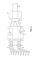
- FIG. 2 therein illustrated is a depiction of the system employed to manufacture a splittable ribbon as defined by this invention.
- the main elements of the system depicted in Figure 2 include: the optical fiber spools 4, 4A; the optical fibers 2, 2A; a positioning apparatus 5, 5A; a single coating die 6; a first curing chamber 8; a first alignment die 9; a second alignment die 10; and a second curing chamber 11.
- a plurality of optical fibers 2, 2A are drawn from spools 4, 4A continuously.
- the optical fibers 2, 2A from the spools 4, 4A are passed through a positioning apparatus 5, 5A, where the respective optical fibers 2, 2A for each subunit 7, 7A are placed in a parallel and planar relationship with other optical fibers 2, 2A to be placed in the same subunit 7, 7A at a distance required for the particular subunit design that is being manufactured.
- the single coating die 6 has multiple exit lands so as to allow the coating of multiple ribbon subunits 7, 7A simultaneously.
- ribbon matrix resin 3 is applied to each grouping of optical fibers 2, 2A to produce subunits 7, 7A.
- Any acceptable or commonly used fiber optic coating or ribbon matrix resin may be used when coating the subunits 7, 7A. Examples include any commercially available UV-curable acrylate with the desired material properties.
- single coating die 6 is to be manufactured to ensure proper exterior dimensions for the subunits 7, 7A after coating. As these dimensions will vary in any application, they are not important to the present invention.
- the subunits 7, 7A exit the single coating die 6 they pass through a first curing chamber 8, in which the fiber optic coating or ribbon matrix resin 3 is partially cured.
- Any conventional curing process can be chosen.
- An example of a commonly used curing process would be the use of ultraviolet light to partially cure the subunit coating.
- the curing process must be chosen in accordance with that which is required to facilitate polymerization of the ribbon matrix or resin material chosen.
- the environment within the first curing chamber is oxygen rich so that the oxygen inhibits polymerization on the surface of the newly made subunits 7, 7A.
- An oxygen content equal to, or possibly greater than, that of normal atmosphere will reduce the degree of photoinitiation on the materials surface because the oxygen is a reaction inhibitor.
- the preferred embodiment also includes a first alignment die 9 through which the partially cured subunits 7, 7A pass.
- the first alignment die 9 is to be manufactured such that a small distance will be maintained between the subunits 7,7A as they pass through the first curing chamber 8, and the first alignment die 9 will ensure that the subunits maintain a parallel and planar relationship. This is represented in Figure 3, depicting the subunits 7, 7A at a small distance from each other in a parallel and planar relationship.
- the subunits 7, 7A After the partially cured subunits 7, 7A pass through the first curing chamber 8, and the first alignment die 9, the subunits 7, 7A enter a second alignment die 10 which is manufactured and designed to force the plurality of subunits 7, 7A to contact each other as shown in Figure 4, creating a cross-link connection or web between the ribbon matrix resin 3 of each subunit 7, 7A as the subunit coating's surfaces cure, thus creating the ribbon unit 12.
- the second alignment die 10 forces the subunits 7, 7A together such that the fiber optic coating or ribbon matrix resin 3 at the cross-link connection or web will be narrower than that of the main portion of the subunits 7, 7A creating a cross-link web 13.
- the ribbon unit 12 After the plurality of the subunits 7, 7A pass through the second alignment die 10 creating the ribbon unit 12, the ribbon unit 12 enter a second curing chamber 11, in which the fiber optic coating or ribbon matrix resin 3 is completely cured.
- the curing chamber 11 is to be designed to complete the proper curing of the fiber optic coating or ribbon matrix resin 3, as required by the coating or resin 3 type chosen.
- the oxygen content in the second curing chamber 11 should be minimized to allow the reactive fiber optic coating or ribbon matrix resin 3 to cure completely. If a material is chosen as the ribbon coating or resin, where polymerization occurs by some means other than by exposure to appropriate wavelength radiation, it may be necessary to use an inhibitor other than oxygen. If this is the case, the use of an appropriate inhibitor should be considered within the scope of this invention.
- the method of cure in the second curing chamber 11 can be any commonly used curing process which is needed for the particular fiber optic coating or ribbon matrix resin 3 chosen. Again, for example, a curing process employing ultraviolet light may be used to complete the curing process.
- the fiber optic coating or ribbon matrix resin 3 is cured over the entire ribbon unit 12, including the cross-link web(s) 13 located in each ribbon unit 12 between the plurality of subunits 7, 7A.
- the cross-link web 13 creates a location of stress concentration providing a suitable separation point between the newly created subunits 14, 15, therefore, avoiding damage to the optical fibers 2, 2A located within the subunits 14, 15, and ensuring that adequate fiber optic coating or ribbon matrix resin 3 remains for proper protection of the optical fibers 2, 2A.
- the present invention provides a novel method and apparatus by which to manufacture an easily splittable optical fiber in a single-step process, where the invention includes arranging individual groups of insulated optical fibers into a flat, side-by-side configuration; having multiple groups of optical fibers (two or more) pass through a single coating die having multiple exit lands, producing subunits; having the subunits pass through a first chamber to partially cure the coating of the subunits, while keeping the subunits close together using a first alignment die; bringing the subunits in contact with each other on their sides through a second alignment die; and finally presenting the joined subunits to a second curing chamber where the coating is completely cured.
- the subunit's surfaces will be cross-linked at the locations of contact and each subunit can be easily split from the rest of the ribbon unit when desired. Because of the partial curing before the subunits are joined, the location of the cross-link web will be thinner than the remainder of the subunits, therefore, creating a location of stress concentration allowing the ribbon unit to be pulled apart. This stress concentration location will allow the ribbon unit to be divided easily in a proper location without the risk of damaging the fibers or their coating.
Landscapes
- Physics & Mathematics (AREA)
- General Physics & Mathematics (AREA)
- Optics & Photonics (AREA)
- Engineering & Computer Science (AREA)
- Manufacturing & Machinery (AREA)
- Surface Treatment Of Glass Fibres Or Filaments (AREA)
- Mechanical Coupling Of Light Guides (AREA)
Applications Claiming Priority (2)
| Application Number | Priority Date | Filing Date | Title |
|---|---|---|---|
| US699422 | 1991-05-13 | ||
| US69942200A | 2000-10-31 | 2000-10-31 |
Publications (2)
| Publication Number | Publication Date |
|---|---|
| EP1202097A2 true EP1202097A2 (de) | 2002-05-02 |
| EP1202097A3 EP1202097A3 (de) | 2004-04-07 |
Family
ID=24809247
Family Applications (1)
| Application Number | Title | Priority Date | Filing Date |
|---|---|---|---|
| EP01402451A Withdrawn EP1202097A3 (de) | 2000-10-31 | 2001-09-25 | Trennbares, optisches Faserflachband und Herstellungsverfahren dafür |
Country Status (2)
| Country | Link |
|---|---|
| EP (1) | EP1202097A3 (de) |
| JP (1) | JP2002182085A (de) |
Cited By (1)
| Publication number | Priority date | Publication date | Assignee | Title |
|---|---|---|---|---|
| WO2023091302A1 (en) | 2021-11-18 | 2023-05-25 | Corning Research & Development Corporation | Intermittently bonded optical fiber ribbon and method of preparing same |
Families Citing this family (1)
| Publication number | Priority date | Publication date | Assignee | Title |
|---|---|---|---|---|
| JP2006126376A (ja) * | 2004-10-27 | 2006-05-18 | Tomoegawa Paper Co Ltd | 光ファイバ構造体及びそれを用いたファンアウト光ファイバ構造体並びにそれらの作製方法 |
Family Cites Families (4)
| Publication number | Priority date | Publication date | Assignee | Title |
|---|---|---|---|---|
| GB8506499D0 (en) * | 1985-03-13 | 1985-04-17 | Telephone Cables Ltd | Optical fibre assemblies/cables |
| JP2573632B2 (ja) * | 1987-11-26 | 1997-01-22 | 住友電気工業株式会社 | テープ状光ファイバ心線の製造装置 |
| JPH04166805A (ja) * | 1990-10-30 | 1992-06-12 | Fujikura Ltd | 分割型光ファイバテープ心線の製造方法 |
| FR2776396B1 (fr) * | 1998-03-19 | 2001-11-30 | Alsthom Cge Alkatel | Procede de fabrication d'un multiruban de fibres optiques separable en au moins deux rubans de fibres optiques |
-
2001
- 2001-09-25 EP EP01402451A patent/EP1202097A3/de not_active Withdrawn
- 2001-09-26 JP JP2001293467A patent/JP2002182085A/ja not_active Withdrawn
Cited By (2)
| Publication number | Priority date | Publication date | Assignee | Title |
|---|---|---|---|---|
| WO2023091302A1 (en) | 2021-11-18 | 2023-05-25 | Corning Research & Development Corporation | Intermittently bonded optical fiber ribbon and method of preparing same |
| EP4433856A4 (de) * | 2021-11-18 | 2025-10-08 | Corning Res & Dev Corp | Intermittierend gebondetes glasfaserband und verfahren zur herstellung davon |
Also Published As
| Publication number | Publication date |
|---|---|
| JP2002182085A (ja) | 2002-06-26 |
| EP1202097A3 (de) | 2004-04-07 |
Similar Documents
| Publication | Publication Date | Title |
|---|---|---|
| JP4049154B2 (ja) | 光ファイバテープ心線 | |
| KR100759198B1 (ko) | 광섬유 구조체 및 그 제조방법 | |
| US6731844B2 (en) | Identification of optical ribbons | |
| CN105229510B (zh) | 光纤带芯线及光缆 | |
| US5611017A (en) | Fiber optic ribbon cable with pre-installed locations for subsequent connectorization | |
| US20060088258A1 (en) | Optical fiber wiring sheet and method of manufacturing same | |
| US20140314382A1 (en) | Optical fiber cord | |
| CN1238466A (zh) | 光纤多条带及其制造方法 | |
| TW201915529A (zh) | 間歇連結型光纖帶及間歇連結型光纖帶的製造方法 | |
| JP2012027130A (ja) | 光ファイバテープ心線および光ケーブル | |
| CA2301472A1 (en) | Optical fiber arrays | |
| JPH01138518A (ja) | テープ状光ファイバ心線 | |
| JP2573633B2 (ja) | テープ状光ファイバ心線の製造装置 | |
| JP2002090589A (ja) | リボン光ファイバケーブル及び光ファイバコーティング用ダイ | |
| US20230393350A1 (en) | Optical fiber ribbon and method for manufacturing optical fiber ribbon | |
| WO2005101080A1 (ja) | 光ファイバテープユニット及び光ファイバケーブル | |
| EP3955040A1 (de) | Optisches faserband, matrize und herstellungsverfahren für ein optisches faserband | |
| US5995693A (en) | Method of making an optical fiber ribbon with improved planarity and an optical fiber ribbon with improved planarity | |
| JP2002182085A (ja) | 引き裂き可能なリボンの設計および製造方法 | |
| JPH06273649A (ja) | 分割型光ファイバテープ心線の製造方法 | |
| JPH04166805A (ja) | 分割型光ファイバテープ心線の製造方法 | |
| JPH01137208A (ja) | テープ状光ファイバ心線 | |
| JP2573631B2 (ja) | テープ状光ファイバ心線の製造装置 | |
| JPH01271715A (ja) | 分割型光ファイバテープ | |
| JPH01120510A (ja) | 光ファイバカップラの製造方法 |
Legal Events
| Date | Code | Title | Description |
|---|---|---|---|
| PUAI | Public reference made under article 153(3) epc to a published international application that has entered the european phase |
Free format text: ORIGINAL CODE: 0009012 |
|
| AK | Designated contracting states |
Kind code of ref document: A2 Designated state(s): AT BE CH CY DE DK ES FI FR GB GR IE IT LI LU MC NL PT SE TR |
|
| AX | Request for extension of the european patent |
Free format text: AL;LT;LV;MK;RO;SI |
|
| RTI1 | Title (correction) |
Free format text: SPLITTABLE OPTICAL FIBRE RIBBON AND METHOD OF MANUFACTURE |
|
| PUAL | Search report despatched |
Free format text: ORIGINAL CODE: 0009013 |
|
| AK | Designated contracting states |
Kind code of ref document: A3 Designated state(s): AT BE CH CY DE DK ES FI FR GB GR IE IT LI LU MC NL PT SE TR |
|
| AX | Request for extension of the european patent |
Extension state: AL LT LV MK RO SI |
|
| RIC1 | Information provided on ipc code assigned before grant |
Ipc: 7C 03C 25/10 B Ipc: 7G 02B 6/44 A |
|
| STAA | Information on the status of an ep patent application or granted ep patent |
Free format text: STATUS: THE APPLICATION IS DEEMED TO BE WITHDRAWN |
|
| 18D | Application deemed to be withdrawn |
Effective date: 20040401 |