EP1202107A2 - Un chauffage de ITO - Google Patents
Un chauffage de ITO Download PDFInfo
- Publication number
- EP1202107A2 EP1202107A2 EP01309167A EP01309167A EP1202107A2 EP 1202107 A2 EP1202107 A2 EP 1202107A2 EP 01309167 A EP01309167 A EP 01309167A EP 01309167 A EP01309167 A EP 01309167A EP 1202107 A2 EP1202107 A2 EP 1202107A2
- Authority
- EP
- European Patent Office
- Prior art keywords
- heater
- conductive
- lcd according
- electrodes
- dummy cell
- Prior art date
- Legal status (The legal status is an assumption and is not a legal conclusion. Google has not performed a legal analysis and makes no representation as to the accuracy of the status listed.)
- Withdrawn
Links
Images
Classifications
-
- G—PHYSICS
- G02—OPTICS
- G02F—OPTICAL DEVICES OR ARRANGEMENTS FOR THE CONTROL OF LIGHT BY MODIFICATION OF THE OPTICAL PROPERTIES OF THE MEDIA OF THE ELEMENTS INVOLVED THEREIN; NON-LINEAR OPTICS; FREQUENCY-CHANGING OF LIGHT; OPTICAL LOGIC ELEMENTS; OPTICAL ANALOGUE/DIGITAL CONVERTERS
- G02F1/00—Devices or arrangements for the control of the intensity, colour, phase, polarisation or direction of light arriving from an independent light source, e.g. switching, gating or modulating; Non-linear optics
- G02F1/01—Devices or arrangements for the control of the intensity, colour, phase, polarisation or direction of light arriving from an independent light source, e.g. switching, gating or modulating; Non-linear optics for the control of the intensity, phase, polarisation or colour
- G02F1/13—Devices or arrangements for the control of the intensity, colour, phase, polarisation or direction of light arriving from an independent light source, e.g. switching, gating or modulating; Non-linear optics for the control of the intensity, phase, polarisation or colour based on liquid crystals, e.g. single liquid crystal display cells
-
- G—PHYSICS
- G02—OPTICS
- G02F—OPTICAL DEVICES OR ARRANGEMENTS FOR THE CONTROL OF LIGHT BY MODIFICATION OF THE OPTICAL PROPERTIES OF THE MEDIA OF THE ELEMENTS INVOLVED THEREIN; NON-LINEAR OPTICS; FREQUENCY-CHANGING OF LIGHT; OPTICAL LOGIC ELEMENTS; OPTICAL ANALOGUE/DIGITAL CONVERTERS
- G02F1/00—Devices or arrangements for the control of the intensity, colour, phase, polarisation or direction of light arriving from an independent light source, e.g. switching, gating or modulating; Non-linear optics
- G02F1/01—Devices or arrangements for the control of the intensity, colour, phase, polarisation or direction of light arriving from an independent light source, e.g. switching, gating or modulating; Non-linear optics for the control of the intensity, phase, polarisation or colour
- G02F1/13—Devices or arrangements for the control of the intensity, colour, phase, polarisation or direction of light arriving from an independent light source, e.g. switching, gating or modulating; Non-linear optics for the control of the intensity, phase, polarisation or colour based on liquid crystals, e.g. single liquid crystal display cells
- G02F1/133—Constructional arrangements; Operation of liquid crystal cells; Circuit arrangements
- G02F1/1333—Constructional arrangements; Manufacturing methods
- G02F1/133382—Heating or cooling of liquid crystal cells other than for activation, e.g. circuits or arrangements for temperature control, stabilisation or uniform distribution over the cell
-
- G—PHYSICS
- G02—OPTICS
- G02F—OPTICAL DEVICES OR ARRANGEMENTS FOR THE CONTROL OF LIGHT BY MODIFICATION OF THE OPTICAL PROPERTIES OF THE MEDIA OF THE ELEMENTS INVOLVED THEREIN; NON-LINEAR OPTICS; FREQUENCY-CHANGING OF LIGHT; OPTICAL LOGIC ELEMENTS; OPTICAL ANALOGUE/DIGITAL CONVERTERS
- G02F1/00—Devices or arrangements for the control of the intensity, colour, phase, polarisation or direction of light arriving from an independent light source, e.g. switching, gating or modulating; Non-linear optics
- G02F1/01—Devices or arrangements for the control of the intensity, colour, phase, polarisation or direction of light arriving from an independent light source, e.g. switching, gating or modulating; Non-linear optics for the control of the intensity, phase, polarisation or colour
- G02F1/13—Devices or arrangements for the control of the intensity, colour, phase, polarisation or direction of light arriving from an independent light source, e.g. switching, gating or modulating; Non-linear optics for the control of the intensity, phase, polarisation or colour based on liquid crystals, e.g. single liquid crystal display cells
- G02F1/133—Constructional arrangements; Operation of liquid crystal cells; Circuit arrangements
- G02F1/1333—Constructional arrangements; Manufacturing methods
- G02F1/1335—Structural association of cells with optical devices, e.g. polarisers or reflectors
- G02F1/13363—Birefringent elements, e.g. for optical compensation
-
- G—PHYSICS
- G02—OPTICS
- G02F—OPTICAL DEVICES OR ARRANGEMENTS FOR THE CONTROL OF LIGHT BY MODIFICATION OF THE OPTICAL PROPERTIES OF THE MEDIA OF THE ELEMENTS INVOLVED THEREIN; NON-LINEAR OPTICS; FREQUENCY-CHANGING OF LIGHT; OPTICAL LOGIC ELEMENTS; OPTICAL ANALOGUE/DIGITAL CONVERTERS
- G02F1/00—Devices or arrangements for the control of the intensity, colour, phase, polarisation or direction of light arriving from an independent light source, e.g. switching, gating or modulating; Non-linear optics
- G02F1/01—Devices or arrangements for the control of the intensity, colour, phase, polarisation or direction of light arriving from an independent light source, e.g. switching, gating or modulating; Non-linear optics for the control of the intensity, phase, polarisation or colour
- G02F1/13—Devices or arrangements for the control of the intensity, colour, phase, polarisation or direction of light arriving from an independent light source, e.g. switching, gating or modulating; Non-linear optics for the control of the intensity, phase, polarisation or colour based on liquid crystals, e.g. single liquid crystal display cells
- G02F1/133—Constructional arrangements; Operation of liquid crystal cells; Circuit arrangements
- G02F1/1333—Constructional arrangements; Manufacturing methods
- G02F1/1347—Arrangement of liquid crystal layers or cells in which the final condition of one light beam is achieved by the addition of the effects of two or more layers or cells
Definitions
- the invention relates to an ITO heater, particularly to such a heater for a liquid crystal display or LCD.
- Liquid crystal displays are extensively used in many applications.
- the liquid crystal layer acts as a light modulating mechanism controlling light transmission or reflection.
- This light modulating mechanism can be controlled electrically.
- the response time of the liquid crystal materials used in LCDs is usually temperature dependent, especially for more viscous liquid crystal fluids. For example, the response is very sluggish and slow when the temperature is low. Some way of regulating the temperature is required. When the surrounding temperature is too low, some heat has to be pumped in to bring the temperature of the device to a reasonable value. This can be in an external way, where the display is in a temperature controlled environment.
- This arrangement is expensive as the whole environment has to be brought to a desired operating temperature for the LCD, and can also be difficult to control in any event.
- a heater for a liquid crystal display characterised by a dummy cell, adapted for use in the LCD, by a heater, and by the heater being embedded in the dummy cell.
- a liquid crystal display comprising an active liquid crystal cell for optical modulation, characterised by a dummy cell adapted for optical compensation comprising two substrates with liquid crystal therebetween, by a heater, the heater comprising a transparent conductive layer applied to one of the substrates, and by the dummy cell further comprising electrically conductive spacing means for simultaneously maintaining a desired cell gap and equalizing the electrical potential between the two substrates.
- the display may comprise a double STN (DSTN) display which may have a dummy cell adapted for optical compensation.
- DSTN double STN
- a device including an LCD display as hereinbefore defined.
- the device may be mounted in a vehicle, e.g. an automobile, although a lorry, truck, van, motorcycle, ship, boat or aircraft could utilise such a device.
- a vehicle e.g. an automobile, although a lorry, truck, van, motorcycle, ship, boat or aircraft could utilise such a device.
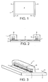
- a heater 1 for electrical or electronic components such as liquid crystal displays (LCDs) such as the DSTN display 2 of Fig. 4, comprising a substrate 3 to which is applied a layer 4 of transparent conductive material, in the embodiment illustrated indium tin oxide (ITO), and electrodes 5 secured electrically conductively thereto over the width thereof and extending therebeyond for connection with a source of power (not shown).
- ITO indium tin oxide
- the electrodes 5 have extensions 6 for connection directly or by wires with a source of alternating applied voltage, in order to actuate the heater to produce heat.
- the electrodes 5 are substantially parallel whereby to provide for uniform heat distribution.
- the substrate is suitably of glass and transparent, according to an embodiment of the invention.
- Conductive transparent indium tin oxide (ITO) patterned or non-patterned is coated on the substrate.
- the two conductive electrodes e.g. metal strip or rod, or flexible printed circuit
- Conductive adhesives 7 are applied to the ITO surface. These adhesives 7 are normally cut in a long strip which are placed at the opposite margins of the substrate which is orthogonal, suitably rectangular.
- the width of the electrodes 5 is normally between 1.5mm and 4mm and the length is the width of the substrate 3 or the width of the ITO coating 4.
- the conductive electrodes extend outside the substrate or are elongated by means of soldering with connecting wires to provide the extensions.
- the elongated portions of extensions 6 of the conductive electrodes 5 are connected to a voltage supply (either DC or AC, preferably square wave AC). When a voltage is applied, the ITO is heated up by means of resistive power dissipation.
- the rate of heating up the display is dependent on the voltage and waveform applied to the conductive electrodes of the ITO heater.
- the "warm up" time for bringing the temperature to that desired is shortened when the voltage (and therefore the power) of the ITO surface is increased or the resistance of the ITO is decreased.
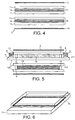
- a typical double STN (DSTN) liquid crystal display 2 This comprises, typically top and bottom polarisers 9, 10 and sandwiched therebetween a dummy cell 11 and an active cell 12 each comprising a pair of transparent substrates 13 with a liquid crystal layer 14 therebetween.
- a perimeter seal epoxy 15 with conductive spacers at the edges of the dummy and active cells and sealing the liquid crystal layers 14 between the transparent substrate 13.
- a majority of applications of a DSTN is in the dashboards or consoles of automotives.
- the cold environment of the automotives greatly reduces the optical performance and increases response time of the liquid crystal displays. Because of this temperature dependence, the display is best maintained at a suitable temperature.
- one of the transparent substrates of the dummy cell is used as an ITO heater, see Fig. 5 in this case, when the ITO heater is ON, there may be some potential difference between the ITO of the upper substrate and the lower substrate of the dummy cell. This may deteriorate the optical compensation of the dummy cell. This phenomenon is called "false triggering".
- Conductive epoxy or epoxy blended with some conductive spacers is used for this dummy cell where the ITO heater sits. This conductive perimeter epoxy equalizes the potential of the two transparent substrates so as to minimize the occurrence of false triggering. It is also used to maintain a uniform desired cell gap. There are two main points to secure the use of the dummy cell as the heating element.
- the first one is the conductive adhesive between the electrode and the ITO surface which determines the maximum current.
- the second one is the conductive perimeter epoxy between the two glass substrates of the dummy cell, which eliminates false triggering and improves resistance to EMI.
- the sheet resistivity of the ITO coating on the other substrate is selected to be much bigger than that of the ITO heater. A ratio of more than 10:1 is appropriate. This arrangement also ensures no chance of open circuit between the ITO electrodes because of large current flowing through the conductive spacers. To shorten the "warm up" time, a larger power dissipated from the ITO heater is required. It needs a larger affordable current in the ITO heater.
- the affordable current is increased.
- the conductive epoxy one can increase conductive spacer density in the epoxy or use asymmetric resistivities. That means, one of the substrates has a large ITO resistivity so that the current flowing through the conductive epoxy is much reduced. After the display is heated up to the desired temperature, a smaller power is required in balancing the heat loss due to cooling the environment.
- the ITO heater consists of a (patterned or non-patterned) transparent ITO layer coated on a substrate (e.g. glass substrate), a pair of conductive electrodes (e.g. metal strips or rods, or flexible printed circuit) that is adhered to the ITO surface by some conductive adhesives e.g. anisotropic conductive film (ACF) or conductive glues.
- conductive adhesives e.g. anisotropic conductive film (ACF) or conductive glues.
- ACF anisotropic conductive film
- the exposed conductive electrodes can be covered by some protective and insulating material such as silicone.
- the advantage of using conductive adhesives in connecting the conductive electrodes on the ITO surface over using clips for electrical conduction on the ITO surface is that the former method has better adhesion, less ohmic drop and, more importantly the electric current density on the ITO surface is more uniform over the whole contacting area. This is especially important for the case of double STN (DSTN) where the heater is normally put on either one of the interior surfaces or both of the dummy cell. This ensures that the current flux is below some threshold value, resulting in no false triggering of deteriorated optical compensation,
- the mechanical adhesion between the electrodes on the ITO surface can be strengthened by additional clipping. Usually an alternating voltage is applied to the ITO heater to heat up the display.
- the "warm up" time needed to bring the temperature up to a desired level is mainly dependent on the applied voltage and waveform, the resistance of the ITO heater, the mass of the transparent substrate, the temperature difference between the display and the surrounding.
- the current should not exceed a certain threshold value. This limiting current value is mainly determined by the maximum tolerable loading of the conductive adhesives. As a consequence, there is a minimum warm up time in raising a certain temperature for a given ITO resistivity.
- a DSTN is made up of two polarisers, two liquid crystal layers with four transparent substrates (two transparent substrates and one liquid crystal layer forming the active layer acting for light modulation and the other two transparent substrates and one liquid crystal layer forming the dummy layer acting for optical compensation).
- a schematic is found in Fig. 4. When the ITO heater is incorporated into the DSTN display, some slight adjustment in the substrate size and ITO resistivity has to be considered.
- a schematic is found in Fig. 5.
- the dummy cell acts as light compensation and the active cell is a light modulating mechanism.
- the glue used to connect the electrodes physically and electrically shorted to the ITO surface can be any effective conductive glue other than anisotropic conductive film (ACF).
- the electrodes may be located at any suitable position on the ITO surface other than at the edges as illustrated. Thus they may be located at two opposite shorter or two opposite longer edges of a rectangular substrate. Resistive heat is generated in the ITO surface, the power being dependent on the resistance of the ITO heater and the voltage and waveform supplied across the electrodes of the ITO heater.
- the resistivities of the ITO surface of a DSTN dummy cell are suitably chosen so that the current flowing from one transparent substrate of the dummy cell to the other transparent substrate is safe and below the critical value tolerable to the conductive perimeter epoxy.
- the conductive adhesives of the ITO heater are selected so that current flowing from a conductive electrode of the ITO to the ITO surface is safe and tolerable to the conductive adhesive. This is to ensure the structural integrity of the heater, and DSTN device, in use.
- the dimension of the substrate is adjusted to allow for placement of the electrodes 5.
- Protective and insulating materials are used to cover and protect the conductive electrodes of the ITO heater.
- a display When used with a DSTN display such a display does not evidence false triggering in optical compensation when the ITO heater is turned on, and moreover such a display shows improved resistance to electromagnetic interference (EMI).
- EMI electromagnetic interference
- the ITO heating element is embedded inside the dummy cell of the DSTN display, no ITO is exposed to any humidity or air (either encapsulated inside the cells and covered by liquid crystals or covered by protective and insulating materials at the areas of electrical contacts).
- the whole DSTN has good reliability against harsh environment.
- the ITO surface is inserted inside the dummy LCD cell, so that there is no ITO corrosion due to the effects of ambient atmosphere, e.g. moisture and air, in use.
- the ITO surface is thus embedded inside the dummy LCD cell of the DSTN.
- the insertion of the ITO heater is highly cost effective.
- the epoxy in the lamination of the dummy cell is electrically conductive (equalizing the electric potentials of the two ITO surfaces in the z-direction) so that there is no false triggering. Electrical contact between the conductive electrodes and the ITO surface can be further enhanced by additional mechanical means such as securing clips (not shown).
- the pixel gap of the Varitronix invention is maintained to be fine and is able to be adopted in high resolution displays.
- a heater according to the invention may be placed on any surface of an LCD, e.g. inside or outside, whether in contact with the liquid crystal layer or not.
Landscapes
- Physics & Mathematics (AREA)
- Nonlinear Science (AREA)
- Chemical & Material Sciences (AREA)
- Crystallography & Structural Chemistry (AREA)
- General Physics & Mathematics (AREA)
- Optics & Photonics (AREA)
- Mathematical Physics (AREA)
- Liquid Crystal (AREA)
Applications Claiming Priority (2)
| Application Number | Priority Date | Filing Date | Title |
|---|---|---|---|
| GB0026616 | 2000-10-31 | ||
| GBGB0026616.3A GB0026616D0 (en) | 2000-10-31 | 2000-10-31 | A heater |
Publications (2)
| Publication Number | Publication Date |
|---|---|
| EP1202107A2 true EP1202107A2 (fr) | 2002-05-02 |
| EP1202107A3 EP1202107A3 (fr) | 2003-10-01 |
Family
ID=9902293
Family Applications (1)
| Application Number | Title | Priority Date | Filing Date |
|---|---|---|---|
| EP01309167A Withdrawn EP1202107A3 (fr) | 2000-10-31 | 2001-10-30 | Un chauffage de ITO |
Country Status (7)
| Country | Link |
|---|---|
| US (1) | US7023519B2 (fr) |
| EP (1) | EP1202107A3 (fr) |
| JP (1) | JP2002202520A (fr) |
| KR (1) | KR20020034941A (fr) |
| CN (1) | CN1263350C (fr) |
| GB (1) | GB0026616D0 (fr) |
| HK (1) | HK1044196A1 (fr) |
Cited By (1)
| Publication number | Priority date | Publication date | Assignee | Title |
|---|---|---|---|---|
| WO2005101105A1 (fr) * | 2004-04-19 | 2005-10-27 | Koninklijke Philips Electronics N.V. | Panneau chauffant et dispositif d'affichage mettant en oeuvre celui-ci |
Families Citing this family (24)
| Publication number | Priority date | Publication date | Assignee | Title |
|---|---|---|---|---|
| JP4119206B2 (ja) * | 2002-08-30 | 2008-07-16 | オプトレックス株式会社 | 液晶表示素子用パネルヒータおよび液晶表示装置 |
| KR100963032B1 (ko) | 2003-09-08 | 2010-06-10 | 엘지디스플레이 주식회사 | 히터용 공통전극을 구비한 액정표시장치 및 그 제조방법 |
| US20060115377A1 (en) * | 2003-09-24 | 2006-06-01 | Jianzhong Fu | Transparent ITO-heating capillary reactor |
| KR101074395B1 (ko) * | 2004-09-13 | 2011-10-17 | 엘지디스플레이 주식회사 | 횡전계형 액정 표시 장치 |
| US7928345B2 (en) * | 2004-10-22 | 2011-04-19 | Ppg Industries Ohio, Inc. | Aircraft windshield defogging/deicing system and method of use thereof |
| US20080164145A1 (en) * | 2006-11-20 | 2008-07-10 | Frederick Vosburgh | Devices and Methods for Antifouling |
| US8173939B1 (en) | 2007-05-10 | 2012-05-08 | Minco Products, Inc. | Thermally conditionable light transmitting subassembly |
| CN100507655C (zh) * | 2007-07-05 | 2009-07-01 | 友达光电股份有限公司 | 液晶显示器及其制作方法 |
| JP4623161B2 (ja) * | 2008-08-07 | 2011-02-02 | 株式会社デンソー | 液晶表示装置 |
| TWM353366U (en) * | 2008-08-29 | 2009-03-21 | Chunghwa Picture Tubes Ltd | Liquid crystal display device |
| US8702307B2 (en) * | 2008-09-05 | 2014-04-22 | American Panel Corporation | Method for determining internal LCD temperature |
| GB2479191B (en) * | 2010-04-01 | 2014-03-19 | Microsaic Systems Plc | Microengineered multipole ion guide |
| EP2385448B1 (fr) * | 2010-05-05 | 2013-03-13 | Siemens Aktiengesellschaft | Agencement de capteur sensible au contact |
| CN102540522A (zh) * | 2012-03-19 | 2012-07-04 | 中航华东光电有限公司 | 一种改善型液晶显示模块及其加固方法 |
| KR20140037627A (ko) * | 2012-09-19 | 2014-03-27 | 삼성전자주식회사 | 액정셔터 및 영상촬영장치 |
| CN102854676B (zh) * | 2012-10-15 | 2016-05-11 | 中航华东光电有限公司 | 一种ito导电玻璃的电极制作方法 |
| CN102981328B (zh) * | 2012-12-24 | 2015-12-23 | 天马微电子股份有限公司 | 负性场序的液晶显示装置及其驱动方法 |
| CN103592789A (zh) * | 2013-12-02 | 2014-02-19 | 深圳晶华显示器材有限公司 | 一种具有触摸及供热功能的液晶显示器及其制造工艺 |
| RU2621282C2 (ru) * | 2015-10-16 | 2017-06-01 | Закрытое акционерное общество "Научно-Производственный Комплекс "Альфа-М" | Электролюминесцентный видеомодуль |
| US10067599B2 (en) * | 2016-07-29 | 2018-09-04 | Ncr Corporation | Touchscreen defroster |
| DE102018217653A1 (de) * | 2018-10-15 | 2020-04-16 | Continental Automotive Gmbh | Anzeige mit einer Anzeigefläche, wobei die Anzeige an einer Außenseite eines Kraftfahrzeuges derart angebracht ist, dass die Anzeigefläche von außen wahrnehmbar ist |
| CN111856830A (zh) * | 2019-09-29 | 2020-10-30 | 法国圣戈班玻璃公司 | 具有分区段调控功能的玻璃以及玻璃分区段调控系统 |
| CN112693311B (zh) * | 2021-01-11 | 2022-04-08 | 安徽天健环保车辆部件有限公司 | 一种全液晶组合仪表的智能温控系统 |
| WO2023033787A1 (fr) * | 2021-08-30 | 2023-03-09 | Switchble Llc | Système et procédé d'ancrage de barre omnibus pour films pdlc |
Family Cites Families (10)
| Publication number | Priority date | Publication date | Assignee | Title |
|---|---|---|---|---|
| US4093355A (en) * | 1977-02-04 | 1978-06-06 | General Motors Corporation | Symmetrical internal heater for liquid crystal display |
| JPS57148722A (en) * | 1981-03-10 | 1982-09-14 | Nissan Motor Co Ltd | Liquid crystal display device |
| JPH01204024A (ja) * | 1988-02-10 | 1989-08-16 | Toshiba Corp | 液晶表示装置 |
| JPH03118517A (ja) * | 1989-09-29 | 1991-05-21 | Sharp Corp | 液晶表示装置 |
| JPH05264956A (ja) * | 1992-03-17 | 1993-10-15 | Casio Comput Co Ltd | 二層stn型液晶表示装置 |
| JPH06260265A (ja) * | 1993-02-27 | 1994-09-16 | Daido Maruta Senko Kk | 透明面状発熱体 |
| JPH06258619A (ja) * | 1993-03-02 | 1994-09-16 | Citizen Watch Co Ltd | 液晶表示装置 |
| WO1999006885A1 (fr) * | 1997-08-01 | 1999-02-11 | Siemens Aktiengesellschaft | Dispositif d'affichage a cristaux liquides pouvant etre chauffe |
| US6128053A (en) * | 1997-10-22 | 2000-10-03 | Mannesmann Vdo Ag | Liquid crystal display with heater |
| JP2001201760A (ja) * | 2000-01-21 | 2001-07-27 | Hosiden Corp | 2層型超捻れネマチック方式液晶表示素子 |
-
2000
- 2000-10-31 GB GBGB0026616.3A patent/GB0026616D0/en not_active Ceased
-
2001
- 2001-10-30 EP EP01309167A patent/EP1202107A3/fr not_active Withdrawn
- 2001-10-31 CN CNB011344180A patent/CN1263350C/zh not_active Expired - Fee Related
- 2001-10-31 JP JP2001335546A patent/JP2002202520A/ja active Pending
- 2001-10-31 US US10/001,674 patent/US7023519B2/en not_active Expired - Fee Related
- 2001-10-31 KR KR1020010067494A patent/KR20020034941A/ko not_active Ceased
-
2002
- 2002-08-07 HK HK02105780.1A patent/HK1044196A1/en unknown
Cited By (2)
| Publication number | Priority date | Publication date | Assignee | Title |
|---|---|---|---|---|
| WO2005101105A1 (fr) * | 2004-04-19 | 2005-10-27 | Koninklijke Philips Electronics N.V. | Panneau chauffant et dispositif d'affichage mettant en oeuvre celui-ci |
| US7847216B2 (en) | 2004-04-19 | 2010-12-07 | Tpo Hong Kong Holding Limited | Panel heater and display device using the same |
Also Published As
| Publication number | Publication date |
|---|---|
| KR20020034941A (ko) | 2002-05-09 |
| US7023519B2 (en) | 2006-04-04 |
| CN1351464A (zh) | 2002-05-29 |
| HK1044196A1 (en) | 2002-10-11 |
| GB0026616D0 (en) | 2000-12-13 |
| CN1263350C (zh) | 2006-07-05 |
| JP2002202520A (ja) | 2002-07-19 |
| EP1202107A3 (fr) | 2003-10-01 |
| US20020089638A1 (en) | 2002-07-11 |
Similar Documents
| Publication | Publication Date | Title |
|---|---|---|
| US7023519B2 (en) | Internal heater embedded in an LCD cell | |
| US9176338B2 (en) | Liquid crystal display panel and method for manufacturing the same | |
| EP0435343B1 (fr) | Appareil à cristal liquide | |
| JP5134286B2 (ja) | 液晶表示装置 | |
| JP7377412B2 (ja) | 調光装置 | |
| TW200523612A (en) | Flat panel display having an isolated EMI layer and integral heater and thermal sensors | |
| KR100856151B1 (ko) | 고분자 분산형 액정표시장치의 전극 단자부 제조방법 | |
| JPH06260265A (ja) | 透明面状発熱体 | |
| CN106154616A (zh) | 液晶膜拼接结构及应用其的调光玻璃、装置 | |
| JP2001201760A (ja) | 2層型超捻れネマチック方式液晶表示素子 | |
| CN110675769A (zh) | 显示装置及电子设备 | |
| JP4694009B2 (ja) | 液晶表示素子用パネルヒータ | |
| JP2007334312A (ja) | ダミー電極を有する表示装置 | |
| JP4838618B2 (ja) | 液晶表示装置用パネルヒータ | |
| JP2001337313A (ja) | 液晶表示装置 | |
| JPH0544815Y2 (fr) | ||
| JP4322605B2 (ja) | 光学素子 | |
| JPH01237521A (ja) | 強誘電性液晶表示装置 | |
| JPS59228290A (ja) | 液晶表示パネル | |
| JP2005215334A (ja) | 液晶表示装置 | |
| JP2006047455A (ja) | 車両用液晶表示装置 | |
| JPH04214528A (ja) | 液晶装置 | |
| CN117270252A (zh) | 一种能够加热的双栅极显示面板及电子设备 | |
| WO2001046750A1 (fr) | Chauffage a couche conductrice, destine a des affichages a cristaux liquides, produisant un motif de chauffage specifique | |
| JP2000231093A (ja) | 液晶表示装置 |
Legal Events
| Date | Code | Title | Description |
|---|---|---|---|
| PUAI | Public reference made under article 153(3) epc to a published international application that has entered the european phase |
Free format text: ORIGINAL CODE: 0009012 |
|
| AK | Designated contracting states |
Kind code of ref document: A2 Designated state(s): AT BE CH CY DE DK ES FI FR GB GR IE IT LI LU MC NL PT SE TR |
|
| AX | Request for extension of the european patent |
Free format text: AL;LT;LV;MK;RO;SI |
|
| PUAL | Search report despatched |
Free format text: ORIGINAL CODE: 0009013 |
|
| AK | Designated contracting states |
Kind code of ref document: A3 Designated state(s): AT BE CH CY DE DK ES FI FR GB GR IE IT LI LU MC NL PT SE TR |
|
| AX | Request for extension of the european patent |
Extension state: AL LT LV MK RO SI |
|
| 17P | Request for examination filed |
Effective date: 20040401 |
|
| AKX | Designation fees paid |
Designated state(s): AT BE CH CY DE DK ES FI FR GB GR IE IT LI LU MC NL PT SE TR |
|
| REG | Reference to a national code |
Ref country code: HK Ref legal event code: WD Ref document number: 1044196 Country of ref document: HK |
|
| STAA | Information on the status of an ep patent application or granted ep patent |
Free format text: STATUS: THE APPLICATION IS DEEMED TO BE WITHDRAWN |
|
| 18D | Application deemed to be withdrawn |
Effective date: 20080503 |