EP1202152B1 - Système de pupitre informatisé - Google Patents
Système de pupitre informatisé Download PDFInfo
- Publication number
- EP1202152B1 EP1202152B1 EP00122712A EP00122712A EP1202152B1 EP 1202152 B1 EP1202152 B1 EP 1202152B1 EP 00122712 A EP00122712 A EP 00122712A EP 00122712 A EP00122712 A EP 00122712A EP 1202152 B1 EP1202152 B1 EP 1202152B1
- Authority
- EP
- European Patent Office
- Prior art keywords
- heat
- communication technology
- housing
- desk system
- computerized
- Prior art date
- Legal status (The legal status is an assumption and is not a legal conclusion. Google has not performed a legal analysis and makes no representation as to the accuracy of the status listed.)
- Expired - Lifetime
Links
Images

Classifications
-
- H—ELECTRICITY
- H05—ELECTRIC TECHNIQUES NOT OTHERWISE PROVIDED FOR
- H05K—PRINTED CIRCUITS; CASINGS OR CONSTRUCTIONAL DETAILS OF ELECTRIC APPARATUS; MANUFACTURE OF ASSEMBLAGES OF ELECTRICAL COMPONENTS
- H05K7/00—Constructional details common to different types of electric apparatus
- H05K7/20—Modifications to facilitate cooling, ventilating, or heating
- H05K7/20009—Modifications to facilitate cooling, ventilating, or heating using a gaseous coolant in electronic enclosures
-
- G—PHYSICS
- G06—COMPUTING OR CALCULATING; COUNTING
- G06F—ELECTRIC DIGITAL DATA PROCESSING
- G06F1/00—Details not covered by groups G06F3/00 - G06F13/00 and G06F21/00
- G06F1/16—Constructional details or arrangements
-
- A—HUMAN NECESSITIES
- A47—FURNITURE; DOMESTIC ARTICLES OR APPLIANCES; COFFEE MILLS; SPICE MILLS; SUCTION CLEANERS IN GENERAL
- A47B—TABLES; DESKS; OFFICE FURNITURE; CABINETS; DRAWERS; GENERAL DETAILS OF FURNITURE
- A47B2200/00—General construction of tables or desks
- A47B2200/0066—Workstations
- A47B2200/0073—Desk with integrated computer
Definitions
- the invention relates to a computer-based console system for communication technology, through that, especially in connection with a customer card, services and information in any area of trade and trade in services can be made available to the customer.
- Such systems also called kiosk systems in technical terminology, already exist in use for some time. These are systems in which a Computers as well as a monitor are integrated into a larger housing made of sheet metal or Wooden assemblies are packed. Customer communication is essential in the previous models using a built-in keyboard, mouse or touchscreen possible. This gives the customer the opportunity to find out about each Offer information on goods or services as well as a personal Customer card that is decoded via a card reader to make purchases.
- Kiosk systems can be used in all conceivable areas of goods or Services are used, just think of petrol stations, department stores, Airports, train stations etc.
- the present invention is based on the object of a computer-based console system to create communication technology in which the internal electrical and / or electronic assemblies against environmental influences such as dust, Moisture, corrosion, heat, cold and vandalism are protected, the generated Heat is still dissipated safely and at the same time the maintenance and Repair effort is reduced to a minimum.
- the computer-based console system has a housing that preferably two closed, perpendicular or at least oblique to the ground arranged housing sections made of thermally conductive material, which for Inclusion of heat-generating electrical and / or electronic devices are suitable.
- thermal bridges are provided to at least one wall surface of the housing sections.
- the heated wall surfaces are surrounded by an aperture profile in such a way that between the housing and panel profile at least one chimney-like Cavity arises, which has at least one opening in its lower end region Has supply of cool air into the cavity and at least one outlet opening in the upper end region of the cavity to release heated air Outside.
- At least one outlet opening leads to the outside, so that the heated air can be released into the environment.
- At least one further heat-conducting element for example a heat pipe or heat pipe, is arranged.
- the heat is essentially opposite to two Side bars running perpendicular to a front panel, so that only a small Percentage of the outside areas are covered for security reasons got to.
- the housing sections are advantageously made of extruded aluminum profiles formed, which are easy to edit, especially connected by laser welding can be.
- Each housing section advantageously has two substantially perpendicular cross bars extending to the front panel and to the side bars, whereby cross bars, Side bars and front panel are each connected by laser welding are. Furthermore, one can be attached essentially parallel to the front panel Rear wall provided, which seals with the side webs and the cross bars is connectable, creating a dust and moisture-proof container for the heat generating units is formed.
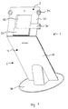
- Fig. 1 is a preferred embodiment of the computer-aided invention Console systems 1 or terminals for communication in perspective Front view shown.
- the housing 2 consists of an upper housing section 3 and a lower housing section 4, which on a base plate 26 is attached.
- the two housing sections 3 and 4 are connected at an angle, preferably screwed, the lower housing section 4 obliquely is mounted in such a way that it bends towards a user and the user sufficient legroom is provided at the lower end.
- the upper housing section 3 is from the connection seam with the lower housing section 4 inclined backwards and upwards to allow the user to operate the console to facilitate. It is important that the upper housing section 3 is not parallel to the ground, but clearly arranged at an angle.
- the two housing sections 3 and 4 consist of extruded Aluminum profiles, and their individual parts are preferably by laser welding, otherwise connected via screw connection.
- the two housing sections 3 and 4 separately from each other to be arranged vertically on a wall or to use as a built-in system. It is also conceivable for the lower housing section 4 mount vertically on a wall and the upper housing section 3 to let it stand diagonally downwards, starting at its top edge the lower housing section 4 is attached.
- the lower housing section 4 is formed on the front by a one-piece Front panel 17, the upper housing section 3 delimited by a front panel 21.
- the lower housing section 4 serves to accommodate heat-generating devices, such as computers, printers, power supplies, etc., while in the upper housing section 3 all operating and display elements are housed.
- heat-generating devices such as computers, printers, power supplies, etc.
- the upper housing section 3 all operating and display elements are housed.
- these visible surface or touch screen 33, card reader 30, keyboard 31 and Voice input unit 32 are housed.
- the terminal can thus be operated preferably both via the keyboard, via the touchscreen and via voice input respectively.
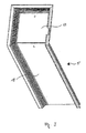
- Fig. 2 the same arrangement is shown in rear view. From this it can be seen that the lower housing section 4 each two arranged parallel to each other and Has side webs 10 and transverse webs 11 running perpendicular to the front plate 17.
- the side webs 10 and the cross webs 11 are rectangular to each other arranged so that an interior delimited by the front panel 17 for receiving computer, printer, etc. (not shown) formed by the Rear wall (not shown) can be closed moisture and dust-tight, as will be described later.
- the front plates 17, 21 extend in the lateral direction over the side webs 10, 23 out. At these outer edges, parallel to the side webs 10, 22 each have a bar 36 formed. On the rear end of the side bars 10, 22 a bar 37 is also formed. These strips 36, 37 are used for Engagement in grooves of the diaphragm profile described in FIGS. 3 to 5.
- Device carriers 7 are arranged in the interior of the housing sections 3, 4 the side webs 10, 22 are attached by clamps or screws. These equipment carriers 7 are used to attach computers, printers, etc. and consist of very thermally conductive material, preferably made of aluminum.
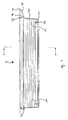
- Fig. 3 is the entire panel profile 5 for the upper and lower housing section shown. It should be noted that after mounting on the housing, the Seal rear walls 18, 24 with the respective side bars and cross bars should. For this purpose, sealing mechanisms are customary for a person skilled in the art used.
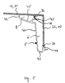
- a preferred embodiment of the diaphragm profile is shown schematically in FIG. 4.
- the left edge represents the upper end region 14 and the right edge the lower end region 12 of an aperture profile 5 or that described later Cavity is when the profile 5 is viewed from the rear left.
- the geometry of the panel profile on the right is symmetrical.
- the Aperture profile 5 consists of a substantially perpendicular to the side webs 10, 22 arranged main section 40, one at one end Has U-shaped extension 41, on the free leg of a groove 44 for receiving is arranged by bar 37.
- the main section faces 40 on a tongue 45 angled substantially perpendicular to it the outer end of which is arranged an extension 42 which is substantially parallel to the main section 40.
- Located towards the other end of the tongue a cantilevered web 46, at the outer end of a further groove 43 is arranged for receiving bar 36.
- the desired ones are placed in the housing 2 used electrical and / or electronic units and to the Device carrier 7 attached. Then the cover profile 5 and the back plates 18, 24 placed on the housing 2 such that the grooves 43 and 44 of the Aperture profile 5 come into engagement with the strips 36 and 37 and the rear walls Seal 18, 24 with the appropriate side bars and cross bars. Aperture profile 5 and rear walls 18, 24 are then with the housing 2 screwed. This means that the device units are safely accommodated against environmental influences.
- Number of cavities adjacent to the side webs could be increased, be it by division from cavity 6 into several small cavities or by adding more Cavities.
- the at least one cavity could do this in the upper end region a connecting channel connected to another cool cavity (not shown) be so that the heated air penetrates into the cool cavity and there by sinking due to cooling and by pushing in warm air from cavity 6 and / or 8 the air is displaced downwards.
Landscapes
- Engineering & Computer Science (AREA)
- Theoretical Computer Science (AREA)
- Microelectronics & Electronic Packaging (AREA)
- Physics & Mathematics (AREA)
- General Engineering & Computer Science (AREA)
- General Physics & Mathematics (AREA)
- Human Computer Interaction (AREA)
- Thermal Sciences (AREA)
- Cooling Or The Like Of Electrical Apparatus (AREA)
- Casings For Electric Apparatus (AREA)
- Hardware Redundancy (AREA)
- Two-Way Televisions, Distribution Of Moving Picture Or The Like (AREA)
- Stored Programmes (AREA)
Claims (10)
- Système de pupitre informatique (1) de la technique de communication comportant un coffret (2), qui présente au moins une, de préférence deux sections de coffret (3, 4) fermées, disposées verticalement ou obliquement par rapport au sol, en matériau au moins principalement conducteur de la chaleur, qui sont adaptées pour recevoir des appareils électriques et/ou électroniques producteurs de chaleur, comme ordinateur, imprimante, boítier secteur, écran etc., avec des ponts thermiques pour conduire la chaleur produite par les appareils électriques vers au moins une surface formant paroi des sections de coffret (3, 4), qui est entourée de manière telle par un profilé écran (5), qu'entre le coffret (2) et le profilé écran (5) il se crée au moins un espace creux (6) similaire à une cheminée, qui présente dans sa zone d'extrémité inférieure (12) au moins une ouverture pour acheminer de l'air froid dans l'espace creux (6), ainsi qu'au moins une ouverture de sortie dans la zone d'extrémité supérieure (14) de l'espace creux (6) pour rejeter l'air réchauffé vers l'extérieur.
- Système de pupitre informatique (1) de la technique de communication selon l'une des revendications précédentes, caractérisé en ce que le coffret (2) présente une section de coffret supérieure (3) pour recevoir des éléments d'affichage et de commande et une section de coffret inférieure (4) pour recevoir un ordinateur, une imprimante, un boítier secteur etc., qui peuvent être reliés les uns aux autres.
- Système de pupitre informatique (1) de la technique de communication selon l'une des revendications précédentes, caractérisé en ce que les appareils électriques et/ou électroniques sont fixés dans les sections de coffret 53, 4) par l'intermédiaire de supports d'appareils (7), qui sont adaptés pour évacuer la chaleur.
- Système de pupitre informatique (1) de la technique de communication selon l'une des revendications précédentes, caractérisé en ce qu'au moins un autre élément conducteur de la chaleur est disposé pour transporter la chaleur des appareils producteurs de chaleur vers des surfaces formant parois des sections de coffret (3, 4).
- Système de pupitre informatique (1) de la technique de communication selon la revendication 6, caractérisé en ce que l'élément conducteur de la chaleur est une caloduc.
- Système de pupitre informatique (1) de la technique de communication selon l'une des revendications précédentes, caractérisé en ce que les surfaces formant parois, vers lesquelles a lieu la conduction thermique, sont en outre agrandies en surface, sur leur côté extérieur.
- Système de pupitre informatique (1) de la technique de communication selon l'une des revendications précédentes, caractérisé en ce que les surfaces formant parois vers lesquelles a lieu la conduction thermique sont deux montants latéraux (10, 22) s'étendant face à face, sensiblement à la perpendiculaire d'une plaque avant (17, 21).
- Système de pupitre informatique (1) de la technique de communication selon l'une des revendications précédentes, caractérisé en ce que les sections de coffret (3, 4) sont formés de profilés d'aluminium extrudés.
- Système de pupitre informatique (1) de la technique de communication selon l'une des revendications précédentes, caractérisé en ce que chaque section de coffret (3, 4) présente deux montants transversaux (11, 23) s'étendant sensiblement à la perpendiculaire de la plaque avant (17, 21) et des montants latéraux (10, 22) et en ce que montants transversaux (11, 23), montants latéraux (10, 22) et plaque avant (17, 21) sont assemblés les uns aux autres, chaque fois par soudage au laser.
- Système de pupitre informatique (1) de la technique de communication selon l'une des revendications précédentes, caractérisé en ce que chaque section de coffret (3, 4) présente une paroi arrière (18, 24) pouvant être fixée sensiblement parallèlement à la plaque avant (17, 21), qui peut être assemblée de manière étanche avec les montants latéraux (10, 22) et les montants transversaux (11, 23).
Priority Applications (4)
| Application Number | Priority Date | Filing Date | Title |
|---|---|---|---|
| DE50000346T DE50000346D1 (de) | 2000-10-18 | 2000-10-18 | Rechnergestütztes Pultsystem |
| EP00122712A EP1202152B1 (fr) | 2000-10-18 | 2000-10-18 | Système de pupitre informatisé |
| DK00122712T DK1202152T3 (da) | 2000-10-18 | 2000-10-18 | Computerbaseret pultsystem |
| AT00122712T ATE221680T1 (de) | 2000-10-18 | 2000-10-18 | Rechnergestütztes pultsystem |
Applications Claiming Priority (1)
| Application Number | Priority Date | Filing Date | Title |
|---|---|---|---|
| EP00122712A EP1202152B1 (fr) | 2000-10-18 | 2000-10-18 | Système de pupitre informatisé |
Publications (2)
| Publication Number | Publication Date |
|---|---|
| EP1202152A1 EP1202152A1 (fr) | 2002-05-02 |
| EP1202152B1 true EP1202152B1 (fr) | 2002-07-31 |
Family
ID=8170124
Family Applications (1)
| Application Number | Title | Priority Date | Filing Date |
|---|---|---|---|
| EP00122712A Expired - Lifetime EP1202152B1 (fr) | 2000-10-18 | 2000-10-18 | Système de pupitre informatisé |
Country Status (4)
| Country | Link |
|---|---|
| EP (1) | EP1202152B1 (fr) |
| AT (1) | ATE221680T1 (fr) |
| DE (1) | DE50000346D1 (fr) |
| DK (1) | DK1202152T3 (fr) |
Family Cites Families (3)
| Publication number | Priority date | Publication date | Assignee | Title |
|---|---|---|---|---|
| US3961666A (en) * | 1972-11-24 | 1976-06-08 | Sony Corporation | Heat dispersion device for use in an electronic apparatus |
| JP2633593B2 (ja) * | 1987-12-10 | 1997-07-23 | 富士通株式会社 | コヒーレント光通信用偏波ダイバーシティ光受信装置 |
| DE4428937C2 (de) * | 1994-08-16 | 1997-01-30 | Juergen Riebling | Computermöbel |
-
2000
- 2000-10-18 AT AT00122712T patent/ATE221680T1/de not_active IP Right Cessation
- 2000-10-18 EP EP00122712A patent/EP1202152B1/fr not_active Expired - Lifetime
- 2000-10-18 DE DE50000346T patent/DE50000346D1/de not_active Expired - Fee Related
- 2000-10-18 DK DK00122712T patent/DK1202152T3/da active
Also Published As
| Publication number | Publication date |
|---|---|
| ATE221680T1 (de) | 2002-08-15 |
| DK1202152T3 (da) | 2002-11-25 |
| EP1202152A1 (fr) | 2002-05-02 |
| DE50000346D1 (de) | 2002-09-05 |
Similar Documents
| Publication | Publication Date | Title |
|---|---|---|
| EP1844637B1 (fr) | Dispositif pour refroidir des unites modulaires electroniques dans des armoires d'equipements et de reseau | |
| EP1231588B1 (fr) | Dispositif pour le support et le refroidissement des écrans plats | |
| EP1719044B1 (fr) | Ensemble de dispositifs | |
| EP1002352B1 (fr) | Boite du type armoire | |
| EP0878991B1 (fr) | Ossature d'armoire support de baies avec dispositif de ventilation | |
| DE3044314C2 (de) | Gehäuse zur Aufnahme von mit Wärme erzeugenden elektronischen Bauteilen bestückten gedruckten Schaltungen | |
| EP1264522B8 (fr) | Coffret de distribution | |
| DE69510443T2 (de) | Gehäuse mit wärmeabgebender einrichtung | |
| EP0311702A1 (fr) | Boîtier pour tiroir | |
| EP2018690A1 (fr) | Armoire électrique munie de deux canaux de refroidissement | |
| DE202006003754U1 (de) | Wärmetauscher | |
| DE3316978A1 (de) | Aufbausystem zur abfuehrung der verlustwaerme von in behaeltern oder schraenken angeordneten elektronischen baugruppen | |
| DE29904928U1 (de) | Gehäuse mit einer Lüftereinrichtung und Lüftereinrichtung | |
| EP1604438B1 (fr) | Element de conduite de fluide de refroidissement et dispositif de conduite de fluide de refroidissement | |
| EP0900621A2 (fr) | Module d'alimentation électrique | |
| DE2844672A1 (de) | Gehaeuse fuer elektronische geraete | |
| EP1399801A2 (fr) | Systeme de guidage d'air de refroidissement | |
| DE69900907T2 (de) | Vereinfachte modulare struktur | |
| DE2211268C3 (de) | Lüftungsanordnung für Einschübe | |
| EP1202152B1 (fr) | Système de pupitre informatisé | |
| EP1869539B1 (fr) | Boitier de service | |
| DE10152510B4 (de) | Schutzgehäuse für elektrische Betriebsmittel | |
| DE20119423U1 (de) | Datensicherheitsschrank | |
| DE3124807C2 (de) | Anordnung zur Stromversorgung | |
| DE9017420U1 (de) | Baugruppenträger |
Legal Events
| Date | Code | Title | Description |
|---|---|---|---|
| GRAG | Despatch of communication of intention to grant |
Free format text: ORIGINAL CODE: EPIDOS AGRA |
|
| GRAG | Despatch of communication of intention to grant |
Free format text: ORIGINAL CODE: EPIDOS AGRA |
|
| GRAH | Despatch of communication of intention to grant a patent |
Free format text: ORIGINAL CODE: EPIDOS IGRA |
|
| PUAI | Public reference made under article 153(3) epc to a published international application that has entered the european phase |
Free format text: ORIGINAL CODE: 0009012 |
|
| 17P | Request for examination filed |
Effective date: 20010406 |
|
| AK | Designated contracting states |
Kind code of ref document: A1 Designated state(s): AT BE CH CY DE DK ES FI FR GB GR IE IT LI LU MC NL PT SE |
|
| AX | Request for extension of the european patent |
Free format text: AL;LT;LV;MK;RO;SI |
|
| GRAH | Despatch of communication of intention to grant a patent |
Free format text: ORIGINAL CODE: EPIDOS IGRA |
|
| GRAA | (expected) grant |
Free format text: ORIGINAL CODE: 0009210 |
|
| AK | Designated contracting states |
Kind code of ref document: B1 Designated state(s): AT BE CH CY DE DK ES FI FR GB GR IE IT LI LU MC NL PT SE |
|
| AX | Request for extension of the european patent |
Free format text: AL;LT;LV;MK;RO;SI |
|
| PG25 | Lapsed in a contracting state [announced via postgrant information from national office to epo] |
Ref country code: GR Free format text: LAPSE BECAUSE OF FAILURE TO SUBMIT A TRANSLATION OF THE DESCRIPTION OR TO PAY THE FEE WITHIN THE PRESCRIBED TIME-LIMIT Effective date: 20020731 Ref country code: IE Free format text: LAPSE BECAUSE OF FAILURE TO SUBMIT A TRANSLATION OF THE DESCRIPTION OR TO PAY THE FEE WITHIN THE PRESCRIBED TIME-LIMIT Effective date: 20020731 Ref country code: FI Free format text: LAPSE BECAUSE OF FAILURE TO SUBMIT A TRANSLATION OF THE DESCRIPTION OR TO PAY THE FEE WITHIN THE PRESCRIBED TIME-LIMIT Effective date: 20020731 |
|
| REF | Corresponds to: |
Ref document number: 221680 Country of ref document: AT Date of ref document: 20020815 Kind code of ref document: T |
|
| REG | Reference to a national code |
Ref country code: GB Ref legal event code: FG4D Free format text: NOT ENGLISH Ref country code: CH Ref legal event code: EP |
|
| REG | Reference to a national code |
Ref country code: IE Ref legal event code: FG4D Free format text: GERMAN |
|
| REF | Corresponds to: |
Ref document number: 50000346 Country of ref document: DE Date of ref document: 20020905 |
|
| PG25 | Lapsed in a contracting state [announced via postgrant information from national office to epo] |
Ref country code: LU Free format text: LAPSE BECAUSE OF NON-PAYMENT OF DUE FEES Effective date: 20021018 |
|
| PG25 | Lapsed in a contracting state [announced via postgrant information from national office to epo] |
Ref country code: BE Free format text: LAPSE BECAUSE OF NON-PAYMENT OF DUE FEES Effective date: 20021031 Ref country code: CY Free format text: LAPSE BECAUSE OF FAILURE TO SUBMIT A TRANSLATION OF THE DESCRIPTION OR TO PAY THE FEE WITHIN THE PRESCRIBED TIME-LIMIT Effective date: 20021031 |
|
| PG25 | Lapsed in a contracting state [announced via postgrant information from national office to epo] |
Ref country code: PT Free format text: LAPSE BECAUSE OF FAILURE TO SUBMIT A TRANSLATION OF THE DESCRIPTION OR TO PAY THE FEE WITHIN THE PRESCRIBED TIME-LIMIT Effective date: 20021118 |
|
| REG | Reference to a national code |
Ref country code: DK Ref legal event code: T3 |
|
| GBT | Gb: translation of ep patent filed (gb section 77(6)(a)/1977) |
Effective date: 20021121 |
|
| AKX | Designation fees paid |
Free format text: AT BE CH CY DE DK ES FI FR GB GR IE IT LI LU MC NL PT SE |
|
| PG25 | Lapsed in a contracting state [announced via postgrant information from national office to epo] |
Ref country code: ES Free format text: LAPSE BECAUSE OF FAILURE TO SUBMIT A TRANSLATION OF THE DESCRIPTION OR TO PAY THE FEE WITHIN THE PRESCRIBED TIME-LIMIT Effective date: 20030130 |
|
| ET | Fr: translation filed | ||
| RAP2 | Party data changed (patent owner data changed or rights of a patent transferred) |
Owner name: IN BLECHVERARBEITUNGSZENTRUM SOEMMERDA GMBH |
|
| REG | Reference to a national code |
Ref country code: IE Ref legal event code: FD4D Ref document number: 1202152E Country of ref document: IE |
|
| NLT2 | Nl: modifications (of names), taken from the european patent patent bulletin |
Owner name: IN BLECHVERARBEITUNGSZENTRUM SOEMMERDA GMBH |
|
| BERE | Be: lapsed |
Owner name: *IN BLECHVERARBEITUNGSZENTRUM SOMMERDA G.M.B.H. Effective date: 20021031 |
|
| PG25 | Lapsed in a contracting state [announced via postgrant information from national office to epo] |
Ref country code: MC Free format text: LAPSE BECAUSE OF NON-PAYMENT OF DUE FEES Effective date: 20030501 |
|
| PLBE | No opposition filed within time limit |
Free format text: ORIGINAL CODE: 0009261 |
|
| STAA | Information on the status of an ep patent application or granted ep patent |
Free format text: STATUS: NO OPPOSITION FILED WITHIN TIME LIMIT |
|
| 26N | No opposition filed |
Effective date: 20030506 |
|
| PGFP | Annual fee paid to national office [announced via postgrant information from national office to epo] |
Ref country code: GB Payment date: 20060925 Year of fee payment: 7 |
|
| PGFP | Annual fee paid to national office [announced via postgrant information from national office to epo] |
Ref country code: SE Payment date: 20061023 Year of fee payment: 7 |
|
| PGFP | Annual fee paid to national office [announced via postgrant information from national office to epo] |
Ref country code: AT Payment date: 20061024 Year of fee payment: 7 Ref country code: CH Payment date: 20061024 Year of fee payment: 7 Ref country code: DK Payment date: 20061024 Year of fee payment: 7 |
|
| PGFP | Annual fee paid to national office [announced via postgrant information from national office to epo] |
Ref country code: NL Payment date: 20061025 Year of fee payment: 7 |
|
| PGFP | Annual fee paid to national office [announced via postgrant information from national office to epo] |
Ref country code: DE Payment date: 20061031 Year of fee payment: 7 Ref country code: IT Payment date: 20061031 Year of fee payment: 7 |
|
| NLS | Nl: assignments of ep-patents |
Owner name: GENERAL POINT OF SALE GMBH Effective date: 20070207 Owner name: INNOWERT GMBH Effective date: 20070207 |
|
| REG | Reference to a national code |
Ref country code: GB Ref legal event code: 732E |
|
| REG | Reference to a national code |
Ref country code: CH Ref legal event code: NV Representative=s name: AMMANN PATENTANWAELTE AG BERN Ref country code: CH Ref legal event code: PUE Owner name: INNOWERT GMBH Free format text: IN BLECHVERARBEITUNGSZENTRUM SOEMMERDA GMBH#AM UNTERWEGE 6#99610 SOEMMERDA (DE) -TRANSFER TO- INNOWERT GMBH#AM UNTERWEGE 6#99610 SOEMMERDA (DE) |
|
| REG | Reference to a national code |
Ref country code: DK Ref legal event code: EBP |
|
| EUG | Se: european patent has lapsed | ||
| GBPC | Gb: european patent ceased through non-payment of renewal fee |
Effective date: 20071018 |
|
| REG | Reference to a national code |
Ref country code: CH Ref legal event code: PL |
|
| NLV4 | Nl: lapsed or anulled due to non-payment of the annual fee |
Effective date: 20080501 |
|
| PG25 | Lapsed in a contracting state [announced via postgrant information from national office to epo] |
Ref country code: DE Free format text: LAPSE BECAUSE OF NON-PAYMENT OF DUE FEES Effective date: 20080501 Ref country code: CH Free format text: LAPSE BECAUSE OF NON-PAYMENT OF DUE FEES Effective date: 20071031 Ref country code: LI Free format text: LAPSE BECAUSE OF NON-PAYMENT OF DUE FEES Effective date: 20071031 |
|
| PG25 | Lapsed in a contracting state [announced via postgrant information from national office to epo] |
Ref country code: AT Free format text: LAPSE BECAUSE OF NON-PAYMENT OF DUE FEES Effective date: 20071018 |
|
| REG | Reference to a national code |
Ref country code: FR Ref legal event code: ST Effective date: 20080630 |
|
| PG25 | Lapsed in a contracting state [announced via postgrant information from national office to epo] |
Ref country code: NL Free format text: LAPSE BECAUSE OF NON-PAYMENT OF DUE FEES Effective date: 20080501 Ref country code: SE Free format text: LAPSE BECAUSE OF NON-PAYMENT OF DUE FEES Effective date: 20071019 Ref country code: DK Free format text: LAPSE BECAUSE OF NON-PAYMENT OF DUE FEES Effective date: 20071031 |
|
| PGFP | Annual fee paid to national office [announced via postgrant information from national office to epo] |
Ref country code: FR Payment date: 20061013 Year of fee payment: 7 |
|
| PG25 | Lapsed in a contracting state [announced via postgrant information from national office to epo] |
Ref country code: GB Free format text: LAPSE BECAUSE OF NON-PAYMENT OF DUE FEES Effective date: 20071018 |
|
| PG25 | Lapsed in a contracting state [announced via postgrant information from national office to epo] |
Ref country code: FR Free format text: LAPSE BECAUSE OF NON-PAYMENT OF DUE FEES Effective date: 20071031 |
|
| PG25 | Lapsed in a contracting state [announced via postgrant information from national office to epo] |
Ref country code: IT Free format text: LAPSE BECAUSE OF NON-PAYMENT OF DUE FEES Effective date: 20071018 |