EP1202308B1 - Clavier à double face avec deux couches de commutation et une couche d'activation - Google Patents
Clavier à double face avec deux couches de commutation et une couche d'activation Download PDFInfo
- Publication number
- EP1202308B1 EP1202308B1 EP01307314A EP01307314A EP1202308B1 EP 1202308 B1 EP1202308 B1 EP 1202308B1 EP 01307314 A EP01307314 A EP 01307314A EP 01307314 A EP01307314 A EP 01307314A EP 1202308 B1 EP1202308 B1 EP 1202308B1
- Authority
- EP
- European Patent Office
- Prior art keywords
- circuit board
- keyboard
- keys
- keymat
- electronic device
- Prior art date
- Legal status (The legal status is an assumption and is not a legal conclusion. Google has not performed a legal analysis and makes no representation as to the accuracy of the status listed.)
- Expired - Lifetime
Links
- 230000004913 activation Effects 0.000 title claims description 43
- 238000000034 method Methods 0.000 claims description 10
- 230000004044 response Effects 0.000 claims description 7
- 230000003213 activating effect Effects 0.000 claims description 6
- 230000007246 mechanism Effects 0.000 claims description 4
- 230000008859 change Effects 0.000 description 4
- 230000000881 depressing effect Effects 0.000 description 4
- 230000009471 action Effects 0.000 description 2
- 230000000994 depressogenic effect Effects 0.000 description 2
- 238000010586 diagram Methods 0.000 description 2
- 230000005484 gravity Effects 0.000 description 2
- 239000000463 material Substances 0.000 description 2
- 239000012528 membrane Substances 0.000 description 2
- 241000282472 Canis lupus familiaris Species 0.000 description 1
- OKTJSMMVPCPJKN-UHFFFAOYSA-N Carbon Chemical compound [C] OKTJSMMVPCPJKN-UHFFFAOYSA-N 0.000 description 1
- HSFWRNGVRCDJHI-UHFFFAOYSA-N alpha-acetylene Natural products C#C HSFWRNGVRCDJHI-UHFFFAOYSA-N 0.000 description 1
- 229910052799 carbon Inorganic materials 0.000 description 1
- 239000011248 coating agent Substances 0.000 description 1
- 238000000576 coating method Methods 0.000 description 1
- 239000011231 conductive filler Substances 0.000 description 1
- 229920001940 conductive polymer Polymers 0.000 description 1
- 239000004020 conductor Substances 0.000 description 1
- 238000001514 detection method Methods 0.000 description 1
- 229920006332 epoxy adhesive Polymers 0.000 description 1
- 230000003993 interaction Effects 0.000 description 1
- 239000011159 matrix material Substances 0.000 description 1
- 239000002184 metal Substances 0.000 description 1
- 239000013528 metallic particle Substances 0.000 description 1
- 239000012811 non-conductive material Substances 0.000 description 1
- 229920001197 polyacetylene Polymers 0.000 description 1
- 229920000642 polymer Polymers 0.000 description 1
- 125000006850 spacer group Chemical group 0.000 description 1
Images




Classifications
-
- H—ELECTRICITY
- H04—ELECTRIC COMMUNICATION TECHNIQUE
- H04M—TELEPHONIC COMMUNICATION
- H04M1/00—Substation equipment, e.g. for use by subscribers
- H04M1/02—Constructional features of telephone sets
- H04M1/0202—Portable telephone sets, e.g. cordless phones, mobile phones or bar type handsets
- H04M1/0206—Portable telephones comprising a plurality of mechanically joined movable body parts, e.g. hinged housings
- H04M1/0241—Portable telephones comprising a plurality of mechanically joined movable body parts, e.g. hinged housings using relative motion of the body parts to change the operational status of the telephone set, e.g. switching on/off, answering incoming call
- H04M1/0245—Portable telephones comprising a plurality of mechanically joined movable body parts, e.g. hinged housings using relative motion of the body parts to change the operational status of the telephone set, e.g. switching on/off, answering incoming call using open/close detection
-
- H—ELECTRICITY
- H01—ELECTRIC ELEMENTS
- H01H—ELECTRIC SWITCHES; RELAYS; SELECTORS; EMERGENCY PROTECTIVE DEVICES
- H01H13/00—Switches having rectilinearly-movable operating part or parts adapted for pushing or pulling in one direction only, e.g. push-button switch
- H01H13/70—Switches having rectilinearly-movable operating part or parts adapted for pushing or pulling in one direction only, e.g. push-button switch having a plurality of operating members associated with different sets of contacts, e.g. keyboard
- H01H13/702—Switches having rectilinearly-movable operating part or parts adapted for pushing or pulling in one direction only, e.g. push-button switch having a plurality of operating members associated with different sets of contacts, e.g. keyboard with contacts carried by or formed from layers in a multilayer structure, e.g. membrane switches
-
- H—ELECTRICITY
- H04—ELECTRIC COMMUNICATION TECHNIQUE
- H04M—TELEPHONIC COMMUNICATION
- H04M1/00—Substation equipment, e.g. for use by subscribers
- H04M1/02—Constructional features of telephone sets
- H04M1/23—Construction or mounting of dials or of equivalent devices; Means for facilitating the use thereof
-
- H—ELECTRICITY
- H01—ELECTRIC ELEMENTS
- H01H—ELECTRIC SWITCHES; RELAYS; SELECTORS; EMERGENCY PROTECTIVE DEVICES
- H01H2217/00—Facilitation of operation; Human engineering
- H01H2217/002—Facilitation of operation; Human engineering actuable from both sides
-
- H—ELECTRICITY
- H01—ELECTRIC ELEMENTS
- H01H—ELECTRIC SWITCHES; RELAYS; SELECTORS; EMERGENCY PROTECTIVE DEVICES
- H01H2223/00—Casings
- H01H2223/01—Mounting on appliance
- H01H2223/018—Mounting on appliance rotatably
-
- H—ELECTRICITY
- H01—ELECTRIC ELEMENTS
- H01H—ELECTRIC SWITCHES; RELAYS; SELECTORS; EMERGENCY PROTECTIVE DEVICES
- H01H2223/00—Casings
- H01H2223/01—Mounting on appliance
- H01H2223/028—Mounting on appliance detachable
-
- H—ELECTRICITY
- H01—ELECTRIC ELEMENTS
- H01H—ELECTRIC SWITCHES; RELAYS; SELECTORS; EMERGENCY PROTECTIVE DEVICES
- H01H2223/00—Casings
- H01H2223/046—Casings convertible
- H01H2223/05—Casings convertible composed of hingedly connected sections
-
- H—ELECTRICITY
- H01—ELECTRIC ELEMENTS
- H01H—ELECTRIC SWITCHES; RELAYS; SELECTORS; EMERGENCY PROTECTIVE DEVICES
- H01H2231/00—Applications
- H01H2231/022—Telephone handset
-
- H—ELECTRICITY
- H04—ELECTRIC COMMUNICATION TECHNIQUE
- H04M—TELEPHONIC COMMUNICATION
- H04M1/00—Substation equipment, e.g. for use by subscribers
- H04M1/02—Constructional features of telephone sets
- H04M1/0202—Portable telephone sets, e.g. cordless phones, mobile phones or bar type handsets
- H04M1/0206—Portable telephones comprising a plurality of mechanically joined movable body parts, e.g. hinged housings
- H04M1/0208—Portable telephones comprising a plurality of mechanically joined movable body parts, e.g. hinged housings characterized by the relative motions of the body parts
- H04M1/0214—Foldable telephones, i.e. with body parts pivoting to an open position around an axis parallel to the plane they define in closed position
-
- H—ELECTRICITY
- H04—ELECTRIC COMMUNICATION TECHNIQUE
- H04M—TELEPHONIC COMMUNICATION
- H04M2250/00—Details of telephonic subscriber devices
- H04M2250/22—Details of telephonic subscriber devices including a touch pad, a touch sensor or a touch detector
Definitions
- the present invention relates generally to a keyboard in an electronic device and, more particularly, to a double-sided keyboard having two keymats, or two sets of individual keys, located on both sides of the keyboard for entering information into an electronic device.
- Man-machine interaction in terms of user input, is of utmost importance in portable communication devices.
- Splitting up one single keyboard into two or more sub-keyboards is one of the ways to improve the efficient use of a communication device.
- the phone keyboard is used when the Communicator functions as a telephone and another separate QWERTY keyboard is used when the Communicator is used for other functions.
- QWERTY keyboard is used when the Communicator is used for other functions.
- the available space and volume for two or more sub-keyboards becomes more limited.
- One way to solve this limited space problem is to implement two keyboards on the two sides of the phone cover, which is also known as an active flip, or on the opposite sides of the device itself.
- each of the two keyboards on the same active flip, or the device itself has a separate circuit board to allow the keys on each keyboard to enter information through their own activation devices on the respective circuit board.
- This type of double-sided keyboard is disclosed, for example, in U.S. Patent No. 6,038,313 (Collins).
- a further example, relating to a remote control transmitter, is disclosed in EP 0 156 651 A2 (Sharp K.K.). Although this type of double-sided keyboard arrangement can save space, it is costly to produce.
- WO 98/03962 A1 Junkyard Dogs, Ltd.
- a display sheet can be activated using membrane switches located on either side of a layer of luminescent material.
- U.S. Patent Nos. 5,715,524 and 5,742,894 disclose a radio communication device, wherein a touch screen display is used to enter information when the device is in an opened position, and a depressible keypad is used when the device is in a closed position.
- a touch screen display is used to enter information when the device is in an opened position
- a depressible keypad is used when the device is in a closed position.
- part of the touch screen display is concealed behind the depressible keypad.
- the keys on the depressible keypad use the concealed portion of the touch screen display to enter information. While this type of multiple keyboard can save space and cost, it is only applicable for those devices that have a touch screen display.
- a double-sided keyboard for entering information in an electronic device comprises:
- the circuit board includes a plurality of connection areas
- the activation sections include a plurality of dome-shaped contact pads, each of which is electrically conductive and located above one of the electrical connection areas, such that the signal is provided to the circuit board in response to the depressing of one of the keys, causing one of the contact pads to make contact with the respective connection area.
- first plurality of keys and some of the second plurality of keys have their own contact pads.
- connection areas are located on the second keymat and underneath the dome-shape contact pads.
- connection areas include pressure sensing elements such that the signal is provided to the circuit board in response to depressing one of the keys, causing one of the activation sections to apply pressure to the respective connection area.
- connection areas include capacitive sensing elements such that the signal is provided to the circuit board in response to depressing one of the keys, causing one of the action sections to affect the capacitance of the respective connection area.
- the keyboard on the active flip such that the first plurality of keys can be accessed from one side of the active flip and the second plurality of keys can be accessed from the other side of the active flip.
- the keyboard can be implemented on the body of the electronic device such that the first plurality of keys can be accessed from one side of the device body and the second plurality of keys can be accessed from the other side of the device body.
- a method of producing a double-sided keyboard for entering information in an electronic device comprises the steps of:
- a method of entering and using information in an electronic device comprises the steps of:
- Figure 1a is a diagrammatic representation illustrating a portable electronic device having a keymat on its cover.
- Figure 1b is a diagrammatic representation illustrating the same electronic device with the cover being opened to expose another keymat.
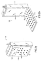
- Figure 2a is a diagrammatic representation illustrating a communication device having a keymat on its cover.
- Figure 2b is a diagrammatic representation illustrating the same communication device with the cover being opened to expose another keymat.
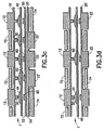
- Figure 3a is a cross sectional view illustrating the double-sided keyboard of the present invention, wherein the keys on the two keymats share the same activation devices in order to activate the circuit board.
- Figure 3b is a cross sectional view illustrating the double-side keyboard, wherein the keys on the two keymats use different activation devices to active the circuit board.
- Figure 3c is a cross sectional view illustrating the double-side keyboard, wherein some keys on the two keymats use the same activation devices but some keys use different activation devices to activate the circuit board.
- Figure 3d is a cross sectional view illustrating the double-sided keyboard of the present invention, wherein the keys on the two keymats share the same activation devices in order to activate a connection area integrated into one of the keymats.
- Figure 3e is a cross sectional view illustrating the double-sided keyboard, wherein the keys on the two keymats use different activation devices to activate a connection area integrated into one of the keymats.
- Figure 3f is a cross sectional view illustrating the double-sided keyboard, wherein some keys on the two keymats use the same activation devices but some keys use different activation devices to activate a connection area integrated into one of the keymats.
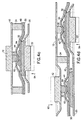
- Figure 4a is a cross sectional view illustrating two keys, which share a common activation device.
- Figure 4b is a cross sectional view illustrating the activation of the circuit board by pressing the key on the first keymat, wherein the keys on the two keymats share the same activation devices.
- Figure 4c is a cross sectional view illustrating the activation of the circuit board by pressing the key on the second keymat, wherein the keys on the two keymats share the same activation devices.
- Figure 4d is a cross sectional view illustrating the activation of the circuit board by pressing a key on either the first or second keymat, wherein the keys on the two keymats use different activation devices.
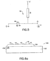
- Figure 5 is a schematic diagram illustrating the principle of activating the circuit board.
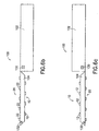
- Figure 6a is a diagrammatic representation of an electronic device having a switching mechanism to define a keyboard mode when the cover is closed.
- Figure 6b is a diagrammatic representation of the same electronic device as illustrated in Figure 6a, wherein the switching mechanism defines another keyboard mode when the cover is open.
- Figure 6c is a diagrammatic representation of the same electronic device as illustrated in Figure 6a, wherein a directional switch is used to further define the keyboard modes.
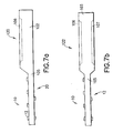
- Figure 7a is a diagrammatic representation of an electronic device having a keyboard as an extended portion of the electronic device.
- Figure 7b is a diagrammatic representation of another electronic device having a keyboard as an extended portion of the electronic device.
- Figures 1a and 1b illustrate a portable electronic device 100 , such as a personal digital assistant, which has a device body 102 and a cover 104.
- a portable electronic device 100 such as a personal digital assistant
- the cover 104 When the cover 104 is in a closed position, it exposes a set of first keys 12, as shown in Figure 1a.
- the cover 104 When the cover 104 is in an open position, it exposes a different set of second keys 22, as shown in Figure 1b.
- the device body 102 has a display 106 to show information to the user. It is understood that the cover 104 is electrically connected to the device body 102 for allowing the keys 12 and 22 to provide signals to the device body 102 for use in the device 100.
- FIGs 2a and 2b illustrate a communication device 110, such as a Nokia Communicator, which includes a phone keyboard or keymat having a plurality of first keys 12, and a larger keyboard or keymat, such as a QWERTY keyboard, having a plurality of second keys 22.
- the communication device 110 has a display 122 to be used as a phone display when the cover 112 is in a closed position, as shown in Figure 2a.
- the communication device 110 also has another display 124 on the device body 114 to be used when the cover 112 is an open position, as shown in Figure 2b. It is understood that the cover 112 is electrically connected to the device body 114 for allowing the keys 12 and 22 to provide signals to the device body 114 for use in the device 110.
- the first keys 12 and the second keys 22 are located on different sides of the cover.
- the key functions of the first keys 12 are different from the key functions of the second keys 22.
- the first keys 12 include number keys 0 to 9, a star key (*), and a pound sign (#), and the second keys 22 include alphabetic keys.
- the first keys 12 have the same key functions as those of the corresponding second keys 22.
- Figures 3a - 3c are cross sectional views of the double-sided keyboard 1 of the present invention, which can be used on the cover 104 of the electronic device 100, as shown in Figures 1a and 1b, or the cover 112 of the communication device 110, as shown in Figures 2a and 2b.
- the double-sided keyboard 1 includes a circuit board 50 having a first side 52 and an opposing second side 54.
- the circuit board 50 is a flexible printed circuit board (PCB), or a flexible connector arrangement, having electrical connection pads 60 for reading the key input on the first side 52.
- PCB flexible printed circuit board
- flexible connector arrangement and electrical connection pads 60 are well known in the art and are not part of the present invention.
- an activation mat 40 having a plurality of dome-shaped, electrically conductive pads 44, is provided to make electrical contact with the electrical connection pads 60 on the circuit board 50 so as to produce electrical signals.
- a first keymat 10 having a plurality of first keys 12 is provided on top of the activation mat 40.
- An actuator 30 is provided under each first key 12 so that when the first key 12 is pressed towards the circuit board 50, the corresponding dome-shaped, electrically conductive contact pad 44 is depressed by the actuator 30, causing the contact pad 44 to make electrical contact with the corresponding electrical connection pad 60 (See Figure 4b, where the electrical connection pad is represented by terminals 62, 64 ).
- a mat cover 72 is provided over the first keymat 10 to physically isolate one first key 12 from another.
- a second keymat 20 having a plurality of second keys 22 is placed adjacent to the second side 54 of the circuit board 50 so that when a second key 22 is pressed towards the circuit board 50, the dome-shaped, electrically conductive contact pad 44 is depressed by a corresponding actuator 30, causing the contact pad 44 to make electrical contact with the corresponding electrical connection pad 60 (See Figure 4c, where the electrical connection pad is represented by terminals 62, 64 ).
- a mat cover 74 is provided over the second keymat 20 to physically isolate one second key 22 from another.
- one or both of the mat covers 72 and 74 can also serve as a mechanical support to the whole keyboard arrangement, especially if individualy keys 12 are used instead of the keymats 10 and 20.
- Figure 3a shows a double-side keyboard 1, wherein the first keys 12 share the same dome-shaped, electrically conductive contact pads 44 with the corresponding second keys 22.
- Figure 3b shows a double-sided keyboard 1, wherein the first keys 12 use different dome-shaped, electrically conductive contact pads 44 from the second keys 22'.
- Figure 3c shows a double-sided keyboard 1, wherein some of the second keys 22 of the second keymat 20 share the same conductive pads 44 with the first keys 12 of the first keymat 10, and some of the second keys 22' use separate conductive pads 44.
- Figures 3d - 3f are cross sectional views of the double-sided keyboard 1' of the the present invention, which can be used on the cover 104 of the electronic device 100, as shown in Figures 1a and 1b, or the cover 112 of the communication device 110 , as shown in Figures 2a and 2b.
- the double-sided keyboard 1 ' is essentially the same as the double-sided keyboard 1, as shown in Figures 3a - 3c, except that the electrical connection pad 60 (See Figure 4c, where the electrical connection pad is represented by terminals 62, 64 ) and the necessary connection circuitry are integrated to the second keymat 20 .
- the second keymat 20 also functions as a circuit board similar to the circuit board 50 as shown in Figures 3a - 3c.
- Figures 4a to 4c are cross sectional views illustrating the activation of the circuit board by pressing a key on either the first or the second keymat, wherein the keys on the two keymats share the same activation devices.
- the connection pad 60 on the circuit board 50 is represented by two conductive terminals 62, 64 provided under each dome-shaped, electrically conductive contact pad 44 . It is preferred that a base support 32 is provided between the second key 22 and the circuit board 50 in the area around the terminals 62, 64.
- the terminals 62, 64 act like an open switch.
- the actuator 30 depresses the dome-shaped, electrically conductive contact pad 44 into contact with the terminals 62, 64, as shown in Figure 4b.
- the terminals 62, 64 act like a closed switch, wherein the terminals 62, 64 are electrically connected.
- Figure 4c shows that the terminals 62, 64 can also be electrically connected when the second key 22 is pressed toward the circuit board 50 along a direction denoted by an arrow 94 from its original position, shown in phantom.
- the base support 32 distorts the flexible circuit board 50.
- the distorted circuit board 50 pushes the activation mat 40 towards the first keymat 10, depressing the dome-shaped, contact pad 44 into contact with the terminals 62, 64 .
- Figure 4d illustrates the activation of the circuit board 50 by pressing either a first key 12 on the first keymat 10 or a second key 22' on the second keymat 20 , wherein the keys 12 , 22' use different contact pads 44 .
- FIG. 5 is a schematic diagram illustrating the principle of activating the circuit board 50 involving the terminals 62, 64.
- the terminals 62, 64 act like a switch, which can be closed with the electrically conductive contact 44.
- the terminal 62 is connected to the electrical ground G and the terminal 64 is connected to an output terminal O, which is connected to a voltage source having a voltage level V through a resistor R.
- the voltage at the output terminal O is equal to or slightly lower than V.
- the terminals 62, 64 are electrically connected to each other by the contact 44, the output terminal O is electrically grounded.
- the contact 44 is caused to make contact with the terminals 62, 64, it provides a signal 130 indicative of the voltage change at the output terminal O.
- the connector arrangement on the circuit board 50 is shared by both the first keymat 10 and the second keymat 20, but it is preferred that the key functions of the keymat 10 and the keymat 20 are not the same. Because the same activation mat 40, or the like, can be pressed on either side thereof, the electronic circuitry in the electronic device that uses the keyboard 1 should be able to recognize which one of the keymats 10, 12 is being used. As shown in Figure 6a, it is possible to install in the electronic device 100 a contact switch 130, which is operatively connected to the cover 104 and the device body 102.
- the switch 130 is operable at two different states (open and closed, for example) such that when the cover 104 is closed, as shown in Figures 1a and 6a, the keyboard 1 ( Figures 3a - 4d) functions in accordance with the input from the first keys 12 of the first keymat 10. However, when the cover 104 is open, as shown in Figures 1b and 6b, the keyboard 1 functions in accordance with the input from second keys 22 of the second keymat 20. It is well known that a mobile phone that has a phone cover uses an active flip or the like to connect and disconnect a phone call. A similar device can be used for the switch 130.
- the keyboard 1 can function differently when the first keymat 10 is facing upward as opposed to when the second keymat 20 is facing upward. It is possible to choose the active side by user selection.
- the double-sided keyboard 1 or 1' is implemented on a cover of an electronic device. It is possible that the double-sided keyboard 1 or 1' is a non-movable part of an electronic device 120 or 122 , as shown in Figures 7a and 7b. As shown in Figure 7a, the double-sided keyboard is an extended portion 105 of the device body 102 of the electronic device 120, which includes a display 106. As shown in Figure 7b, the double-sided keyboard is an extended portion 105 of the device body 103 of the electronic device 122, which has two displays 106 and 107 corresponding to the keymats 10 and 12 .
- the dome-shaped contact pad 44 is electrically conductive so that when the contact pad 44 makes contact with the terminals 62, 64, it electrically connects the terminals.
- the contact pad 44 it is not necessary for the contact pad 44 to be electrically conductive and for it to physically make contact with the terminals 62, 64 in order to activate the circuit board 50.
- the contact pad 44 can be a poor electric conductor but it can cause a change in the capacitance between the terminals 62, 64 when it is in close proximity to the terminals 62, 64. This capacitance change can, in turn, cause a frequency change in a signal or other electrical characteristics of the signal in the circuit board 50.
- the activation mat 40 can be made of a variety of materials. For example, it can be made of a non-conductive material and then made conductive by a flexible metal coating; it can be made from an inherently conductive polymer membrane such as polyacetylene; or it can be made of a polymer matrix embedded with a conductive filler, such as carbon or other metallic particles. It is also possible that only the underside of the dome-shaped contact pad 44 is made conductive by having a flexible, conductive epoxy adhesive provided thereon, while the rest of the activation mat 40 is electrically non-conductive. Furthermore, the resistor R in Figure 5 can be the same in all keys 12, 22 , but it can be different in different keys.
Landscapes
- Engineering & Computer Science (AREA)
- Signal Processing (AREA)
- Input From Keyboards Or The Like (AREA)
- Push-Button Switches (AREA)
- Manufacture Of Switches (AREA)
- Switch Cases, Indication, And Locking (AREA)
- Telephone Set Structure (AREA)
Claims (20)
- Clavier double face (1) pour entrer des informations dans un dispositif électronique, le clavier (1) comprenant :caractérisé en ce que :une carte de circuit imprimé (50) comportant une première face (52) et une seconde face opposée (54) ;une première matrice de touches (10) comportant une première pluralité de touches (12) placée sur la première face (52) ; etune seconde matrice de touches (20) comportant une seconde pluralité de touches (22) placée sur la seconde face (54) ;une matrice d'activation (40) comporte une pluralité de sections électro-conductrices (44) placées entre la première matrice de touches (10) et la carte de circuit imprimé (50) pour permettre à la première et à la seconde matrice de touches (10, 20) d'activer la carte de circuit imprimé (50) en réponse à l'enfoncement d'au moins l'une des touches (12, 22), ce qui amène au moins une section électro-conductrice (44) à se connecter fonctionnellement à la première face (52) de la carte de circuit imprimé (50) pour fournir un signal indicatif des informations à utiliser dans le dispositif électronique (100).
- Clavier (1) selon la revendication 1, dans lequel la carte de circuit imprimé (50) est intégrée dans la seconde matrice de touches (20).
- Clavier (1) selon la revendication 1, comprenant, en outre, un capot de matrice (72) adjacent à la première matrice de touches (10) éloigné de la première face (52) de la carte de circuit imprimé (50) pour séparer la première pluralité de touches (12).
- Clavier (1) selon la revendication 1, comprenant, en outre, un capot de matrice (74) adjacent à la seconde matrice de touches (20) éloigné de la seconde face (54) de la carte de circuit imprimé (50) pour séparer la seconde pluralité de touches (22).
- Clavier (1) selon la revendication 1, dans lequel les sections électro-conductrices (44) comprennent une pluralité de segments en forme de dôme pour établir un contact électrique avec la carte de circuit imprimé (50) pour activer la carte de circuit imprimé (50).
- Clavier (1) selon la revendication 5, dans lequel les segments en forme de dôme (44) sont partagés avec la première et la seconde pluralité de touches (12, 22) de sorte que chaque segment en forme de dôme (44) peut être amené à établir un contact électrique avec la carte de circuit imprimé (50) par l'une de la première pluralité de touches (12) et par l'une de la seconde pluralité de touches (22).
- Clavier (1) selon la revendication 1, dans lequel les sections électro-conductrices (44) comprennent :une première pluralité de segments en forme de dôme pour établir un contact électrique avec la carte de circuit imprimé (50) pour activer la carte de circuit imprimé (50) en enfonçant l'une de la première pluralité de touches (12) ; etune seconde pluralité de segments en forme de dôme pour établir un contact électrique avec la carte de circuit imprimé (50) pour activer la carte de circuit imprimé (50) en enfonçant l'une de la seconde pluralité de touches (22).
- Clavier (1) selon la revendication 1, dans lequel la première matrice de touches (10) est capable d'activer la carte de circuit imprimé (50) seulement lorsque le clavier (1) est orienté dans une première direction, et la seconde matrice de touches (20) est capable d'activer la carte de circuit imprimé (50) seulement lorsque le clavier (1) est orienté dans une seconde direction différente de la première direction.
- Clavier (1) selon la revendication 8, comprenant, en outre, un mécanisme (132) connecté fonctionnellement à la carte de circuit imprimé (50) pour déterminer si le clavier (1) est orienté dans la première ou la seconde direction et pour fournir un autre signal indicatif de la direction de l'orientation à utiliser dans le dispositif électronique (100).
- Clavier (1) selon la revendication 8, dans lequel la première matrice de touches (10) est positionnée au-dessus de la carte de circuit imprimé (50) lorsque le clavier est orienté dans la première direction.
- Clavier (1) selon la revendication 8, dans lequel la seconde matrice de touches (20) est positionnée au-dessus de la carte de circuit imprimé (50) lorsque le clavier est orienté dans la seconde direction.
- Dispositif électronique (100) comprenant :un clavier (1) selon la revendication 1 ;un capot amovible (104) pour la mise en oeuvre dudit clavier (1) ; etun corps de dispositif (102) connecté mécaniquement et électriquement au capot amovible (104) pour permettre à la carte de circuit imprimé (50) de transférer le signal entre le capot (104) et le corps de dispositif (102).
- Dispositif électronique (100) comprenant :un clavier (1) selon la revendication 1 ;un corps de dispositif (102), etune partie allongée (105) pour la mise en oeuvre dudit clavier (1), dans lequel le corps de dispositif (102) est connecté électriquement à la partie allongée (105) pour permettre à la carte de circuit imprimé (50) de transférer le signal entre la partie allongée (105) et le corps de dispositif (102).
- Procédé destiné à la fabrication d'un clavier double face (1) pour entrer des informations dans un dispositif électronique (100), comprenant les étapes consistant à :caractérisé par :fournir une carte de circuit imprimé (50) comportant une première face (52) etune seconde face opposée (54) ;fournir une première matrice de touches (10) comportant une première pluralité de touches (12) sur la première face (52) de la carte de circuit imprimé (50) ; etfournir une seconde matrice de touches (20) comportant une seconde pluralité de touches (22) sur la seconde face (54) de la carte de circuit imprimé (50) ;la fourniture d'une matrice d'activation (40) entre la première matrice de touches (10) et la carte de circuit imprimé (50), la matrice d'activation (40) comportant une pluralité de sections électro-conductrices (44) pour permettre à la première et à la seconde matrice de touches (10, 20) d'activer la carte de circuit imprimé (50) en réponse à l'enfoncement d'au moins l'une des touches (12, 22), ce qui amène au moins une section électro-conductrice (44) à se connecter fonctionnellement à la première face (52) de la carte de circuit imprimé (50) pour fournir un signal indicatif des informations à utiliser dans le dispositif électronique (100).
- Procédé selon la revendication 14, dans lequel la première matrice de touches (10) est capable d'activer la carte de circuit imprimé (50) seulement lorsque le clavier (1) est orienté dans une première direction, et la seconde matrice de touches (20) est capable d'activer la carte de circuit imprimé (50) seulement lorsque le clavier (1) est orienté dans une seconde direction différente de la première direction.
- Procédé selon la revendication 15, comprenant, en outre, l'étape consistant à fournir un mécanisme (132) connecté fonctionnellement à la carte de circuit imprimé (50) pour déterminer si le clavier (1) est orienté dans la première ou la seconde direction et pour fournir un autre signal indicatif de la direction de l'orientation à utiliser dans le dispositif électronique (100).
- Procédé selon la revendication 14, dans lequel les sections électro-conductrices (44) comprennent une pluralité de segments en forme de dôme pour établir un contact électrique avec la carte de circuit imprimé (50) pour activer la carte de circuit imprimé (50) en enfonçant au moins l'une de la première ou de la second pluralité de touches (12, 22).
- Procédé selon la revendication 14, dans lequel les sections électro-conductrices (44) comprennent :une pluralité de premiers segments en forme de dôme pour établir un contact électrique avec la carte de circuit imprimé (50) pour activer la carte de circuit imprimé (50) en enfonçant au moins l'une de la première pluralité de touches (12) ; etune pluralité de seconds segments en forme de dôme pour établir un contact électrique avec la carte de circuit imprimé (50) pour activer la carte de circuit imprimé (50) en enfonçant au moins l'une de la seconde pluralité de touches (22).
- Procédé selon la revendication 14, dans lequel la seconde matrice de touches (20) fait partie intégrante de la carte de circuit imprimé (50).
- Procédé destiné à l'entrée et à l'utilisation d'informations dans un dispositif électronique (100), comprenant les étapes consistant à :caractérisé par :enfoncer au moins l'une d'une première pluralité de touches (12) d'une première matrice de touches (10) adjacente à une première face d'une matrice d'activation (40) comportant une pluralité de sections électro-conductrices (44) pour amener au moins l'une des sections électro-conductrices (44) de la matrice d'activation (40) à se connecter fonctionnellement à une carte de circuit imprimé (50), la carte de circuit imprimé (50) comportant une première face (52) et une seconde face opposée (54), dans lequel la première face (52) de la carte de circuit imprimé (50) est située à côté d'une seconde face de la matrice d'activation (40) à l'opposé de la première face de celle-ci, pour fournir un premier signal ; etutiliser le premier signal pour réaliser une fonction associée à celui-ci dans le dispositif électronique (100) ;l'enfoncement d'au moins l'une d'une seconde pluralité de touches (22) adjacente à une seconde face (54) de la carte de circuit imprimé (50) pour amener au moins l'une des sections électro-conductrices (44) de la matrice d'activation (40) à se connecter fonctionnellement à la première face (52) de la carte de circuit imprimé (50) pour fournir un second signal ; etl'utilisation du second signal pour réaliser une fonction associée à celui-ci dans le dispositif électronique (100).
Applications Claiming Priority (2)
| Application Number | Priority Date | Filing Date | Title |
|---|---|---|---|
| US702539 | 2000-10-31 | ||
| US09/702,539 US6630925B1 (en) | 2000-10-31 | 2000-10-31 | Double-sided keyboard having two keymats and one activation mat |
Publications (3)
| Publication Number | Publication Date |
|---|---|
| EP1202308A2 EP1202308A2 (fr) | 2002-05-02 |
| EP1202308A3 EP1202308A3 (fr) | 2002-12-04 |
| EP1202308B1 true EP1202308B1 (fr) | 2005-11-02 |
Family
ID=24821623
Family Applications (1)
| Application Number | Title | Priority Date | Filing Date |
|---|---|---|---|
| EP01307314A Expired - Lifetime EP1202308B1 (fr) | 2000-10-31 | 2001-08-29 | Clavier à double face avec deux couches de commutation et une couche d'activation |
Country Status (4)
| Country | Link |
|---|---|
| US (1) | US6630925B1 (fr) |
| EP (1) | EP1202308B1 (fr) |
| JP (1) | JP2002197939A (fr) |
| DE (1) | DE60114540T2 (fr) |
Families Citing this family (37)
| Publication number | Priority date | Publication date | Assignee | Title |
|---|---|---|---|---|
| US6760015B2 (en) * | 2000-10-31 | 2004-07-06 | Nokia Corporation | Double-sided keyboard for use in an electronic device |
| US7039033B2 (en) * | 2001-05-07 | 2006-05-02 | Ixi Mobile (Israel) Ltd. | System, device and computer readable medium for providing a managed wireless network using short-range radio signals |
| US7054440B2 (en) * | 2001-05-23 | 2006-05-30 | Telefonaktiebolaget Lm Ericsson (Publ) | Method and apparatus for keypad representation in a mobile communication device |
| US20050030917A1 (en) * | 2001-08-17 | 2005-02-10 | Amit Haller | Device, system, method and computer readable medium obtaining a network attribute, such as a DNS address, for a short distance wireless network |
| US7016334B2 (en) * | 2001-08-17 | 2006-03-21 | Ixi Mobile ( Israel) Ltd. | Device, system, method and computer readable medium for fast recovery of IP address change |
| US20040081129A1 (en) * | 2001-08-17 | 2004-04-29 | Amit Haller | Device, system, method and computer readable medium for selectively attaching to a cellular data service |
| US20040125762A1 (en) * | 2001-08-17 | 2004-07-01 | Amit Haller | Device, system, method and computer readable medium for attaching to a device identifited by an access point name in a wide area network providing particular services |
| US7295532B2 (en) * | 2001-08-17 | 2007-11-13 | Ixi Mobile (R & D), Ltd. | System, device and computer readable medium for providing networking services on a mobile device |
| EP1440556A1 (fr) * | 2001-10-16 | 2004-07-28 | Koninklijke Philips Electronics N.V. | Clavier de saisie de donnees et appareil electronique comportant ce clavier |
| US6957045B2 (en) * | 2001-10-26 | 2005-10-18 | Ixi Mobile (Israel) Ltd. | Device, system, computer readable medium and method for providing status information of devices in a short distance wireless network |
| US6845097B2 (en) | 2001-11-21 | 2005-01-18 | Ixi Mobile (Israel) Ltd. | Device, system, method and computer readable medium for pairing of devices in a short distance wireless network |
| US7016648B2 (en) * | 2001-12-18 | 2006-03-21 | Ixi Mobile (Israel) Ltd. | Method, system and computer readable medium for downloading a software component to a device in a short distance wireless network |
| US7013112B2 (en) * | 2001-12-18 | 2006-03-14 | Ixi Mobile (Israel) Ltd. | Method, system and computer readable medium for making a business decision in response to information from a short distance wireless network |
| US20030153280A1 (en) * | 2002-02-08 | 2003-08-14 | Joe Kopp | Handset having a retractable keypad |
| US7257430B2 (en) * | 2002-05-11 | 2007-08-14 | Motorola, Inc. | Self configuring multiple element portable electronic device |
| US20040204000A1 (en) * | 2002-05-30 | 2004-10-14 | Aaron Dietrich | Mobile communication device including an array sensor |
| US7499029B2 (en) * | 2002-08-02 | 2009-03-03 | Fujitsu Limited | Information processing apparatus with double-sided operable keyboard |
| US20040021639A1 (en) * | 2002-08-02 | 2004-02-05 | Fujitsu Limited | Information processing apparatus with double-sided operable keyboard |
| US6909878B2 (en) * | 2002-08-20 | 2005-06-21 | Ixi Mobile (Israel) Ltd. | Method, system and computer readable medium for providing an output signal having a theme to a device in a short distance wireless network |
| US7356571B2 (en) * | 2002-10-07 | 2008-04-08 | Ixi Mobile (R&D), Ltd. | System, method and processor readable medium for downloading information within a predetermined period of time to a device in a network responsive to price selection |
| US7167680B2 (en) * | 2003-02-05 | 2007-01-23 | Ixi Mobile (Israel) Ltd. | Method, system and computer readable medium for adjusting output signals for a plurality of devices in a short distance wireless network responsive to a selected environment |
| USD495307S1 (en) | 2003-05-09 | 2004-08-31 | Nokia Corporation | Handset |
| US20040259585A1 (en) * | 2003-06-04 | 2004-12-23 | Avi Yitzchak | Wireless device having dual bus archeticure for interfacing with cellular signals and short-range radio signals |
| US7366901B2 (en) * | 2003-08-01 | 2008-04-29 | Ixi Mobile (R&D), Ltd. | Device, system, method and computer readable medium for identifying and authenticating a cellular device using a short-range radio address |
| US20080120559A1 (en) * | 2006-11-17 | 2008-05-22 | Microsoft Corporation | Switchable user interfaces |
| JP2009111912A (ja) * | 2007-10-31 | 2009-05-21 | Pioneer Electronic Corp | 電子機器等 |
| US20090153491A1 (en) * | 2007-12-14 | 2009-06-18 | Research In Motion Limited | Key in a keypad of an electronic device providing feedback |
| WO2011006498A1 (fr) * | 2009-07-16 | 2011-01-20 | Opdi Technologies A/S | Système interactif et procédé de codage |
| JP5428718B2 (ja) * | 2009-10-01 | 2014-02-26 | 日本電気株式会社 | 携帯端末装置 |
| US8606340B2 (en) | 2010-11-22 | 2013-12-10 | Blackberry Limited | Multi-display mobile device |
| CN202196958U (zh) * | 2011-08-10 | 2012-04-18 | 富士康(昆山)电脑接插件有限公司 | 电连接器 |
| US8760406B2 (en) * | 2012-04-03 | 2014-06-24 | Motorola Mobility Llc | Edge to edge qwerty keypad for a handheld device |
| US10394342B2 (en) * | 2017-09-27 | 2019-08-27 | Facebook Technologies, Llc | Apparatuses, systems, and methods for representing user interactions with real-world input devices in a virtual space |
| AT520820B1 (fr) * | 2018-04-18 | 2019-08-15 | ||
| USD890756S1 (en) | 2018-10-31 | 2020-07-21 | Christie Scott Wall | Keyboard |
| US11086516B2 (en) | 2018-10-31 | 2021-08-10 | Christie Scott Wall | Mobile, versatile, transparent, double-sided data input or control device |
| CN110941350A (zh) * | 2019-11-25 | 2020-03-31 | 深圳市恒怡多精彩科技有限公司 | 一种双面键盘 |
Family Cites Families (9)
| Publication number | Priority date | Publication date | Assignee | Title |
|---|---|---|---|---|
| US3940758A (en) * | 1974-09-20 | 1976-02-24 | Margolin George D | Expandable keyboard for electronic pocket calculators and the like |
| JPS60158342U (ja) | 1984-03-29 | 1985-10-22 | シャープ株式会社 | リモ−トコントロ−ル送信機 |
| JPH01176615A (ja) | 1987-12-29 | 1989-07-13 | Matsushita Electric Ind Co Ltd | 両面入力スイッチ |
| JPH01187718A (ja) | 1988-01-20 | 1989-07-27 | Matsushita Electric Ind Co Ltd | 両面キーボードスイッチ |
| US5742894A (en) | 1995-02-06 | 1998-04-21 | Motorola, Inc. | Radio communication device having a moveable housing element and keypad disposed therein |
| US5715524A (en) | 1995-02-06 | 1998-02-03 | Motorola, Inc. | Radio communication device with movable housing element control |
| ATE427543T1 (de) | 1996-07-23 | 2009-04-15 | Xs Energy International Inc | Elektrolumineszentes anzeigegerat |
| US6038313A (en) | 1997-11-20 | 2000-03-14 | Nortel Networks Corporation | Double sided keyboard for a telephone |
| USD448032S1 (en) * | 2000-11-13 | 2001-09-18 | Timothy C. Talley | Double sided foldable keyboard and display |
-
2000
- 2000-10-31 US US09/702,539 patent/US6630925B1/en not_active Expired - Lifetime
-
2001
- 2001-08-29 DE DE60114540T patent/DE60114540T2/de not_active Expired - Lifetime
- 2001-08-29 EP EP01307314A patent/EP1202308B1/fr not_active Expired - Lifetime
- 2001-10-18 JP JP2001320809A patent/JP2002197939A/ja active Pending
Also Published As
| Publication number | Publication date |
|---|---|
| DE60114540T2 (de) | 2006-07-27 |
| US6630925B1 (en) | 2003-10-07 |
| JP2002197939A (ja) | 2002-07-12 |
| EP1202308A2 (fr) | 2002-05-02 |
| DE60114540D1 (de) | 2005-12-08 |
| EP1202308A3 (fr) | 2002-12-04 |
Similar Documents
| Publication | Publication Date | Title |
|---|---|---|
| EP1202308B1 (fr) | Clavier à double face avec deux couches de commutation et une couche d'activation | |
| US6760015B2 (en) | Double-sided keyboard for use in an electronic device | |
| US6518958B1 (en) | Electronic apparatus having plural entry switches | |
| EP1595386B1 (fr) | Terminal radiotelephonique equipe d'un clavier a double face | |
| CN101431563B (zh) | 移动终端 | |
| CA1241363A (fr) | Commutateur a lames ayant une fiabilite de fonctionnement amelioree et procurant une meilleure sensation tactile | |
| US20090138831A1 (en) | Apparatus and method of determining a user selection in a user interface | |
| EP2367094A1 (fr) | clavier tactile avec retour tactile | |
| KR20080075804A (ko) | 경사 터치 제어패널 | |
| CN100473083C (zh) | 一种键组件 | |
| US6477274B1 (en) | Handwritten character recognition devices and electronic devices incorporating same | |
| MXPA01004666A (es) | Un telefono portatil y un metodo de conectar la energia. | |
| US6670893B1 (en) | Double-sided keyboard having a spacer plate with apertures to hold contacts | |
| WO2008077472A1 (fr) | Construction de bloc de touches et/ou de bloc à effleurement | |
| US20040203525A1 (en) | Electronic device having two-sided keypad and method of forming same | |
| KR100968856B1 (ko) | 키 입력장치 | |
| EP2052313A2 (fr) | Barre de défilement et pavé tactile avec réaction tactile et/ou sonore |
Legal Events
| Date | Code | Title | Description |
|---|---|---|---|
| PUAI | Public reference made under article 153(3) epc to a published international application that has entered the european phase |
Free format text: ORIGINAL CODE: 0009012 |
|
| AK | Designated contracting states |
Kind code of ref document: A2 Designated state(s): AT BE CH CY DE DK ES FI FR GB GR IE IT LI LU MC NL PT SE TR |
|
| AX | Request for extension of the european patent |
Free format text: AL;LT;LV;MK;RO;SI |
|
| PUAL | Search report despatched |
Free format text: ORIGINAL CODE: 0009013 |
|
| AK | Designated contracting states |
Kind code of ref document: A3 Designated state(s): AT BE CH CY DE DK ES FI FR GB GR IE IT LI LU MC NL PT SE TR |
|
| AX | Request for extension of the european patent |
Free format text: AL;LT;LV;MK;RO;SI |
|
| 17P | Request for examination filed |
Effective date: 20030414 |
|
| AKX | Designation fees paid |
Designated state(s): DE FI FR GB NL |
|
| 17Q | First examination report despatched |
Effective date: 20041005 |
|
| GRAP | Despatch of communication of intention to grant a patent |
Free format text: ORIGINAL CODE: EPIDOSNIGR1 |
|
| GRAS | Grant fee paid |
Free format text: ORIGINAL CODE: EPIDOSNIGR3 |
|
| GRAA | (expected) grant |
Free format text: ORIGINAL CODE: 0009210 |
|
| AK | Designated contracting states |
Kind code of ref document: B1 Designated state(s): DE FI FR GB NL |
|
| PG25 | Lapsed in a contracting state [announced via postgrant information from national office to epo] |
Ref country code: FI Free format text: LAPSE BECAUSE OF FAILURE TO SUBMIT A TRANSLATION OF THE DESCRIPTION OR TO PAY THE FEE WITHIN THE PRESCRIBED TIME-LIMIT Effective date: 20051102 |
|
| REG | Reference to a national code |
Ref country code: GB Ref legal event code: FG4D |
|
| REF | Corresponds to: |
Ref document number: 60114540 Country of ref document: DE Date of ref document: 20051208 Kind code of ref document: P |
|
| ET | Fr: translation filed | ||
| PGFP | Annual fee paid to national office [announced via postgrant information from national office to epo] |
Ref country code: NL Payment date: 20060803 Year of fee payment: 6 |
|
| PLBE | No opposition filed within time limit |
Free format text: ORIGINAL CODE: 0009261 |
|
| STAA | Information on the status of an ep patent application or granted ep patent |
Free format text: STATUS: NO OPPOSITION FILED WITHIN TIME LIMIT |
|
| 26N | No opposition filed |
Effective date: 20060803 |
|
| PG25 | Lapsed in a contracting state [announced via postgrant information from national office to epo] |
Ref country code: NL Free format text: LAPSE BECAUSE OF NON-PAYMENT OF DUE FEES Effective date: 20080301 |
|
| NLV4 | Nl: lapsed or anulled due to non-payment of the annual fee |
Effective date: 20080301 |
|
| PGFP | Annual fee paid to national office [announced via postgrant information from national office to epo] |
Ref country code: FR Payment date: 20100824 Year of fee payment: 10 |
|
| REG | Reference to a national code |
Ref country code: FR Ref legal event code: ST Effective date: 20120430 |
|
| PG25 | Lapsed in a contracting state [announced via postgrant information from national office to epo] |
Ref country code: FR Free format text: LAPSE BECAUSE OF NON-PAYMENT OF DUE FEES Effective date: 20110831 |
|
| REG | Reference to a national code |
Ref country code: GB Ref legal event code: 732E Free format text: REGISTERED BETWEEN 20150910 AND 20150916 |
|
| REG | Reference to a national code |
Ref country code: DE Ref legal event code: R082 Ref document number: 60114540 Country of ref document: DE Representative=s name: BECKER, KURIG, STRAUS, DE Ref country code: DE Ref legal event code: R081 Ref document number: 60114540 Country of ref document: DE Owner name: NOKIA TECHNOLOGIES OY, FI Free format text: FORMER OWNER: NOKIA CORP., 02610 ESPOO, FI |
|
| PGFP | Annual fee paid to national office [announced via postgrant information from national office to epo] |
Ref country code: GB Payment date: 20170823 Year of fee payment: 17 Ref country code: DE Payment date: 20170822 Year of fee payment: 17 |
|
| REG | Reference to a national code |
Ref country code: DE Ref legal event code: R119 Ref document number: 60114540 Country of ref document: DE |
|
| GBPC | Gb: european patent ceased through non-payment of renewal fee |
Effective date: 20180829 |
|
| PG25 | Lapsed in a contracting state [announced via postgrant information from national office to epo] |
Ref country code: DE Free format text: LAPSE BECAUSE OF NON-PAYMENT OF DUE FEES Effective date: 20190301 |
|
| PG25 | Lapsed in a contracting state [announced via postgrant information from national office to epo] |
Ref country code: GB Free format text: LAPSE BECAUSE OF NON-PAYMENT OF DUE FEES Effective date: 20180829 |
|
| REG | Reference to a national code |
Ref country code: DE Ref legal event code: R082 Ref document number: 60114540 Country of ref document: DE Representative=s name: BARKHOFF REIMANN VOSSIUS, DE Ref country code: DE Ref legal event code: R081 Ref document number: 60114540 Country of ref document: DE Owner name: WSOU INVESTMENTS, LLC, LOS ANGELES, US Free format text: FORMER OWNER: NOKIA TECHNOLOGIES OY, ESPOO, FI |
|
| REG | Reference to a national code |
Ref country code: GB Ref legal event code: 732E Free format text: REGISTERED BETWEEN 20200820 AND 20200826 |