EP1202433A2 - Verfahren und Vorrichrung zum festklemmen der Wicklungsspulen von Turbogeneratoren unter Benutzung von Spannbolzen - Google Patents
Verfahren und Vorrichrung zum festklemmen der Wicklungsspulen von Turbogeneratoren unter Benutzung von Spannbolzen Download PDFInfo
- Publication number
- EP1202433A2 EP1202433A2 EP01203671A EP01203671A EP1202433A2 EP 1202433 A2 EP1202433 A2 EP 1202433A2 EP 01203671 A EP01203671 A EP 01203671A EP 01203671 A EP01203671 A EP 01203671A EP 1202433 A2 EP1202433 A2 EP 1202433A2
- Authority
- EP
- European Patent Office
- Prior art keywords
- coil windings
- pair
- threaded rod
- clamping apparatus
- retaining platform
- Prior art date
- Legal status (The legal status is an assumption and is not a legal conclusion. Google has not performed a legal analysis and makes no representation as to the accuracy of the status listed.)
- Granted
Links
- 238000004804 winding Methods 0.000 title claims abstract description 91
- 238000000034 method Methods 0.000 title claims description 9
- 239000000463 material Substances 0.000 claims description 13
- 230000013011 mating Effects 0.000 claims description 10
- 239000011347 resin Substances 0.000 claims description 8
- 229920005989 resin Polymers 0.000 claims description 8
- 230000003247 decreasing effect Effects 0.000 claims description 6
- 239000011152 fibreglass Substances 0.000 claims description 5
- 238000003780 insertion Methods 0.000 description 3
- 230000037431 insertion Effects 0.000 description 3
- 230000008901 benefit Effects 0.000 description 2
- 230000006835 compression Effects 0.000 description 2
- 238000007906 compression Methods 0.000 description 2
- 238000012986 modification Methods 0.000 description 2
- 230000004048 modification Effects 0.000 description 2
- 230000000717 retained effect Effects 0.000 description 2
- 239000004593 Epoxy Substances 0.000 description 1
- XEEYBQQBJWHFJM-UHFFFAOYSA-N Iron Chemical group [Fe] XEEYBQQBJWHFJM-UHFFFAOYSA-N 0.000 description 1
- 230000002159 abnormal effect Effects 0.000 description 1
- 230000002411 adverse Effects 0.000 description 1
- 239000004020 conductor Substances 0.000 description 1
- 230000001419 dependent effect Effects 0.000 description 1
- 238000009434 installation Methods 0.000 description 1
- 238000009413 insulation Methods 0.000 description 1
- 239000004033 plastic Substances 0.000 description 1
- 229920000728 polyester Polymers 0.000 description 1
Images


Classifications
-
- H—ELECTRICITY
- H02—GENERATION; CONVERSION OR DISTRIBUTION OF ELECTRIC POWER
- H02K—DYNAMO-ELECTRIC MACHINES
- H02K3/00—Details of windings
- H02K3/46—Fastening of windings on the stator or rotor structure
- H02K3/50—Fastening of winding heads, equalising connectors, or connections thereto
- H02K3/505—Fastening of winding heads, equalising connectors, or connections thereto for large machine windings, e.g. bar windings
Definitions
- This invention relates to the field of turbine generators, and more particularly, this invention relates to a clamping apparatus and method for clamping of stator coil windings within a turbine generator.
- Turbine generators for producing electric power are well known and typically include an end winding portion that includes a stator core having several slots that receive and support conductors.
- the end windings may not be adequately supported within the core slots during operation of the generator and are often subject to severe vibrations and stresses, which may cause adverse structural deformations. Structural deformation may also arise from electromagnetic forces which occur during abnormal short-circuit or fault conditions.
- the support blocks are located radially above and below a respective pair of end turns so that one support block bears against two parallel bottom coils and the other support block bears against two parallel top coils.
- Upper and lower pins are disposed across the support block transverse to the orientation direction of the coils.
- a tensioned banding loop is disposed continuously around the pins on each side of the coils so that the banding loop bears against the pins which, in turn, bear against their adjacent support blocks and coils.
- the pins With the banding loop in position, the pins are rotated to twist the banding loop for taking in excess slack, thereby tightening the banding loop between the coils. Resin dispersed within the banding loop is then cured on site, typically by hot air flowing over the banding loop. The curing process requires additional time and expense to install. Typically, band curing extends work schedules and consequently adds to the overall cost of the turbine generator.
- a clamping apparatus in the '792 disclosure, includes a retaining platform for extending across a pair of coil windings positioned in a spaced relation.
- the retaining platform has a bore extending therethrough.
- a connecting insert member is slidably carried within the bore of the retaining platform.
- the connecting insert member has a through-hole and means for admitting a rod into the through-hole.
- the rod passes through the through-hole of the connecting insert member and includes a bulbous shaped end dimensioned for passing through the bore of the retaining platform while the through-hole of the connecting insert member prevents passage of the bulbous shaped end therethrough.
- tension in the rod biases the platform against the coil windings.
- the connecting insert member comprises separable mating segments as the means for admitting a rod into the through-hole.
- the through-hole of the connecting insert member includes a first dimension that permits passage of the bulbous end therein, and a second dimension that prevents passage of the bulbous end therethrough.
- the connecting insert member has a tapered cross-section for slidably securing the member within the bore of the retaining platform.
- the present invention is advantageous and now provides a clamping apparatus useful for clamping opposing pairs of stator coil windings of a turbine generator in a quick and efficient manner.
- a retaining platform is positioned adjacent one side and across a pair of coil windings having a space therebetween and having a bore extending therethrough that is aligned with the space between the pair of coil windings.
- a connecting insert member is carried within the bore of the retaining platform and has a threaded through-hole aligned with the space between the pair of coil windings.
- a threaded rod extends through the space between the pair of coil windings and through the threaded through-hole of the connecting insert member. This threaded rod mates with the threaded through-hole such that the tension created in the threaded rod during tightening biases the retaining platform against the pair of coil windings.
- the threaded rod is used with shims for increasing or decreasing tension within the threaded rod and increasing or decreasing biasing of the retaining platform against the pair of coil windings.
- the threaded rod is preferably formed from a material wherein the compression of the threads is increased with increased tension.
- An example of such a material is resin treated fiberglass.
- the connecting insert member in one aspect of the invention has a tapered cross-section adjustably secured within the bore of the retaining platform.
- a support block is positioned between the retaining platform and across the pair of coil windings and has an aperture therethrough for aligning with the space between the pair of coil windings and the bore of the retaining platform.
- the connecting insert member includes separable mating segments that include mating arcuate portions forming the through-hole.
- the pair of coil windings are positioned parallel and in a spaced relation, thus having a space therebetween when tension is applied.
- a first retaining platform is positioned adjacent one side and across a first pair of coil windings having a space therebetween.
- This first retaining platform has a bore extending therethrough that is aligned with the space between the first pair of coil windings.
- a second retaining platform is positioned adjacent one side and across a second pair of coil windings having a space therebetween.
- the second retaining platform has a bore extending therethrough for aligning with the space of the second pair of coil windings.
- the first and second pair of coil windings are sandwiched between first and second retaining platforms.
- First and second connecting insert members are each respectively carried within each bore of the retaining platform and each of the connecting insert portions has a threaded through-hole.
- a threaded rod passes through each of the spaces of the first and second pairs of coil windings and passes through the through-holes of the connecting insert members. The threaded rod mates with each threaded through-hole such that tension in the threaded rod biases the retaining platform against the pairs of coil windings.
- a method is disclosed or clamping opposing pairs of stator coil windings of a turbine generator.
- a threaded rod is inserted through a space formed between a pair of coil windings and through a threaded through-hole of a connecting insert member that is received within a bore of a retaining platform positioned adjacent one side and across the pair of coil windings. This threaded rod is tightened hydraulically within the threaded through-hole for biasing the retaining platform against a pair of coil windings.
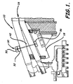
- FIG. 1 illustrates a stator end winding 10 having a radial winding clamp 30 used as a clamping apparatus of the present invention.
- the stator end winding 10 could be part of a power generator (not shown) that includes stator core 14 formed of stator coil windings 16 (also referred to as stator coils) (FIG. 2). The coils are disposed within slots 17 of the stator core 14.
- FIG. 1 illustrates a hydrogen-cooled stator winding bracing of the type where the clamping apparatus of the present invention can be used.
- the radial winding clamp 30 used as a clamping apparatus reduces radial vibration of the individual coil end turns relative to each other, to the strain blocks.
- the coils are typically insulated and as the top and bottom coils provide improved properties where the end turned portions of the coils are pressed during curing to minimize insulation creep in this area and glass-epoxy layers can be applied, providing a foundation for bracing.
- FIGS. 2 and 5 there is illustrated in detail the clamping apparatus 30 used for clamping opposing pairs of stator coil windings 16 such as used in the end winding 10 of the type shown in FIG. 1.
- the clamping apparatus can also be used for other clamping applications, as suggested by those skilled in the art.
- stator coils 16 are secured by the clamping apparatus 30 of the present invention.
- clamping apparatus 30 of the present invention.
- the use of the terms such as upper, lower, top, bottom and the like, by way of example, are relative terms and the structures and methods of the present invention are not limited by the convenience use of such relative terms.
- the illustrated embodiment of the clamping apparatus 30 shown in FIG. 5 includes a top support block 32, which is positioned radially outside a respective pair of top coils 34.
- bottom support blocks (not shown) could be used, they are not required as the prior art applications typically require.
- This top support block 32 is spaced from an adjacent top coil 34 by a layer of conformable material 36, such as resin treated polyester felt or other similar materials known by those skilled in the art.
- the top support block 32 compresses the top coil in an operating position.
- the top support block 32 includes an aperture 38 that is adapted to receive a threaded rod 40, in accordance with the present invention, to secure the stator coils 34 in an operating position.
- the aperture 38 is substantially radially aligned in relation to the axis of the overall machine forming the generator.
- This support block 32 is made of materials that are non-conducting and non-magnetic.
- Strain blocks 42 can also be positioned at various locations to provide support between the top stator coils 34 and bottom coils 44.
- the use of strain blocks 42 is well known to those having ordinary skill in the art.
- the strain blocks 42 are separated from the top and bottom coils 34,44 by a layer of conformable material 46, such as used between the top support block 32 and the top coil 34, including a material such as resin treated felt or other materials known to those skilled in the art.
- a first retaining platform 50 (also referred to as top or upper retaining platform) is positioned adjacent one side and across a first pair of coil windings forming the top coil stator coil windings 34 having a space 34a therebetween, and in one aspect of the present invention, is positioned against the top support block 32.
- the first retaining platform 50 has a bore 52 extending therethrough that is aligned with the space 34a between the first pair of coil windings.
- the first retaining platform 50 defines the bore 52, which has a substantially tapered cross-section as illustrated for receiving a first connecting insert member 54, as described below.
- a second retaining platform 56 (also referred to as bottom or lower retaining platform) is positioned adjacent one side and across the second pair of stator coil windings 44, which have a formed space 44a therebetween.
- the second retaining platform 56 has a bore 58 extending therethrough for aligning with the space 44a of the second pair of coil windings.
- a second connecting insert member 60 is received within the bore 58.
- first or top pair of stator coil windings 34 are positioned parallel in a spaced relation and form the space 34a therebetween, and the second or bottom pair of stator coil windings 44 are positioned parallel and in spaced relation, thus forming a space 44a therebetween.
- the second pair of stator coil windings 44 oppose the first pair of stator coil windings with alignment of the spaces 34a, 44a therebetween and having the strain block 42 separating the first and second pairs of stator coil windings.
- the bores 52,58 in each of the first and second retaining platforms 50,56 is tapered in cross-section and receives the respective first and second connecting insert members 54,60.
- Each of the first and second connecting insert members 54,60 has a threaded through-hole 54a, 60a that is aligned with the formed space in the first and second pairs of coil windings and in the strain block and top support block.
- the threaded rod 40 passes through each of the spaces 34a, 44a of the first and second pairs of coil windings 34,44 and passes through the threaded through-holes 54a, 60a of the connecting insert members 54, 60.
- the threaded rod 40 mate with each threaded through-hole 54a, 60a such that tension is created in the threaded rod 40 during tightening.
- the threaded rod 40 biases the retaining platforms 50, 56 against the pairs of coil windings as the rod is tightened.
- each connecting insert member 54, 60 is formed as separable mating segments 54b, 60b to allow easy insertion within each bore 52, 58 extending through the first and second retaining platforms 50, 56.
- This type of design is advantageous when the threaded rod 40 is formed of a material such that the strength of the threads on the threaded rod are increased with increased tension.
- the threaded rod 40 could be formed of resin treated fiberglass or other plastic or similar material, where, as the tension is increased on the threaded rod, the strength of the threads is increased.
- the tapered angle of the bore within each retaining platform and on the outside surface of the first and second connecting insert members also provides for forces of compression onto the threads and allows an additional force for locking the clamp via the threads and increasing the strength of the material because of pressure from the tapered surfaces.
- resin treated felt 36 is inserted between the second retaining platform 56 and second pair of stator coil windings 44, and the first retaining platform 50, and in the particular embodiment shown, the top support block 32 .
- the first (top) retaining platform 50 is lifted along a lifting edge 71 formed by the groove as shown in FIG. 2 by a hydraulic mechanism that stretches the threaded rod.
- the threaded rod such as formed from fiberglass, has retained tension because it is stretched.
- the shims are then inserted and keep the threaded rod stretched. The shims make up the space, such that when the tension is released, a force is exerted on the coils with the retained tension.
- During insertion as much as 5,000 pounds of force is inserted downward, compressing top and bottom coils. During application, either less or more pressure could be applied, depending on circumstances.
Landscapes
- Engineering & Computer Science (AREA)
- Power Engineering (AREA)
- Manufacture Of Motors, Generators (AREA)
- Insulation, Fastening Of Motor, Generator Windings (AREA)
Applications Claiming Priority (2)
| Application Number | Priority Date | Filing Date | Title |
|---|---|---|---|
| US09/696,848 US6373165B1 (en) | 2000-10-26 | 2000-10-26 | Apparatus and method for clamping turbine generator coil windings using bolted clamp |
| US696848 | 2000-10-26 |
Publications (3)
| Publication Number | Publication Date |
|---|---|
| EP1202433A2 true EP1202433A2 (de) | 2002-05-02 |
| EP1202433A3 EP1202433A3 (de) | 2003-11-12 |
| EP1202433B1 EP1202433B1 (de) | 2011-11-30 |
Family
ID=24798788
Family Applications (1)
| Application Number | Title | Priority Date | Filing Date |
|---|---|---|---|
| EP01203671A Expired - Lifetime EP1202433B1 (de) | 2000-10-26 | 2001-09-27 | Verfahren und Vorrichtung zum Festklemmen der Wicklungsspulen von Turbogeneratoren unter Benutzung von Spannbolzen |
Country Status (2)
| Country | Link |
|---|---|
| US (1) | US6373165B1 (de) |
| EP (1) | EP1202433B1 (de) |
Families Citing this family (5)
| Publication number | Priority date | Publication date | Assignee | Title |
|---|---|---|---|---|
| US6798101B1 (en) | 2003-07-09 | 2004-09-28 | Siemens Westinghouse Power Corporation | Series connector for winding ends of a dynamoelectric machine and associated methods |
| US6969939B1 (en) | 2003-09-08 | 2005-11-29 | Curtiss-Wright Electro-Mechanical Corporation | Bolted connector for electrical equipment |
| US7400072B2 (en) * | 2004-12-10 | 2008-07-15 | Siemens Power Generation, Inc. | Bolted spherical series and phase connector for stator coils of electrical generators |
| US8981606B2 (en) | 2012-05-18 | 2015-03-17 | Siemens Energy, Inc. | Bolted connector for stator coils of an electrical generator |
| CN112968576B (zh) * | 2021-04-13 | 2022-10-25 | 哈尔滨电机厂有限责任公司 | 一种汽轮发电机定子端部鼻端松动处理工艺方法 |
Citations (1)
| Publication number | Priority date | Publication date | Assignee | Title |
|---|---|---|---|---|
| US4563607A (en) | 1984-05-11 | 1986-01-07 | Westinghouse Electric Corp. | Radial clamp assembly for dynamoelectric machine stator coil end turns |
Family Cites Families (21)
| Publication number | Priority date | Publication date | Assignee | Title |
|---|---|---|---|---|
| US1401697A (en) | 1918-07-25 | 1921-12-27 | Westinghouse Electric & Mfg Co | Commutating-pole construction |
| USRE28478E (en) | 1960-06-03 | 1975-07-08 | Winding support system for a dynamoelectric machine | |
| GB970228A (en) * | 1963-06-04 | 1964-09-16 | Gen Electric | End turn support arrangement |
| US3293472A (en) * | 1965-08-09 | 1966-12-20 | Robert W Stevens | End turn support arrangement |
| SE333768B (de) | 1968-10-07 | 1971-03-29 | Asea Ab | |
| SE353991B (de) | 1970-11-02 | 1973-02-19 | Asea Ab | |
| US4371799A (en) | 1977-10-25 | 1983-02-01 | General Electric Company | Permanent magnet field pole for a direct current dynamoelectric machine |
| SE409268B (sv) | 1977-11-30 | 1979-08-06 | Asea Ab | Gaskyld rotor for turbogenerator |
| CH629344A5 (de) | 1978-06-08 | 1982-04-15 | Bbc Brown Boveri & Cie | Vorrichtung zum abstuetzen der feldwicklung eines polrades mit ausgepraegten polen. |
| US4415825A (en) | 1982-01-27 | 1983-11-15 | Westinghouse Electric Corp. | End turn bracing with locking and alignment device |
| US4554475A (en) | 1982-02-25 | 1985-11-19 | Century Electric, Inc. | Field coil air vents for dynamoelectric machine |
| US4488079A (en) * | 1984-03-30 | 1984-12-11 | Westinghouse Electric Corp. | Dynamoelectric machine with stator coil end turn support system |
| US4806807A (en) | 1987-01-09 | 1989-02-21 | Westinghouse Electric Corp. | Method and apparatus for bolted series/phase generator connections |
| US4782579A (en) | 1987-11-03 | 1988-11-08 | Westinghouse Electric Corp. | Method of assembling a precured ring clamp assembly |
| US4942326A (en) | 1989-04-19 | 1990-07-17 | Westinghouse Electric Corp. | Biased securement system for end winding conductor |
| CH680546A5 (de) * | 1989-12-15 | 1992-09-15 | Klaus Weigelt Dr Ing | |
| US5159220A (en) | 1990-06-25 | 1992-10-27 | General Electric Company | Realizations of folded magnet AC motors |
| US5373211A (en) | 1994-02-14 | 1994-12-13 | Westinghouse Electric Corporation | Turbine generator stator end floating winding support |
| US5734220A (en) | 1996-11-07 | 1998-03-31 | Westinghouse Electric Corporation | Preloading system for a clamp of a stator end winding coil |
| US5798595A (en) | 1996-12-30 | 1998-08-25 | Westinghouse Electric Corporation | Vibrational control system for stator coils |
| US5939814A (en) | 1998-01-26 | 1999-08-17 | Siemens Westinghouse Power Corporation | Clamping apparatus for turbine generator coil windings |
-
2000
- 2000-10-26 US US09/696,848 patent/US6373165B1/en not_active Expired - Lifetime
-
2001
- 2001-09-27 EP EP01203671A patent/EP1202433B1/de not_active Expired - Lifetime
Patent Citations (1)
| Publication number | Priority date | Publication date | Assignee | Title |
|---|---|---|---|---|
| US4563607A (en) | 1984-05-11 | 1986-01-07 | Westinghouse Electric Corp. | Radial clamp assembly for dynamoelectric machine stator coil end turns |
Also Published As
| Publication number | Publication date |
|---|---|
| EP1202433B1 (de) | 2011-11-30 |
| US6373165B1 (en) | 2002-04-16 |
| EP1202433A3 (de) | 2003-11-12 |
Similar Documents
| Publication | Publication Date | Title |
|---|---|---|
| US7202587B2 (en) | Method and apparatus for the mounting of and circumferential displacement of radial forces in a stator core assembly | |
| US4563607A (en) | Radial clamp assembly for dynamoelectric machine stator coil end turns | |
| EP0393836A1 (de) | Vorgespanntes Befestigungssystem für Wicklungskopfleiter | |
| CA2119800A1 (en) | Banded electromagnetic stator core | |
| JPH01160334A (ja) | 発電機の固定子鉄心用圧縮組立体及びその使用方法 | |
| CN1031629A (zh) | 电机定子线圈端部用的厚梁支撑结构 | |
| US5436520A (en) | Structure for mounting the winding ends of a stator winding in a dynamoelectric machine | |
| US6373165B1 (en) | Apparatus and method for clamping turbine generator coil windings using bolted clamp | |
| US4037126A (en) | Tieless bracing for supporting end turns of a dynamoelectric machine | |
| US6225726B1 (en) | Apparatus and method for clamping turbine generator coil windings | |
| CN100568667C (zh) | 用于转子和定子叠片的绝缘芯部双头螺柱 | |
| JPH0759286A (ja) | 機械電気変換器内で固定子巻線のワインデイング端部を保持する装置 | |
| US5027500A (en) | Generator rotor slot wedge assembly and disassembly | |
| US4782579A (en) | Method of assembling a precured ring clamp assembly | |
| CA1329471C (en) | Device for pre-tautening of the annular stator core laminations of a large electric generator | |
| EP0941569B1 (de) | Vorspannungsystem einer klammer für statorwickelköpfe | |
| US5926939A (en) | Method for securing a generator end winding system | |
| JPS62279611A (ja) | 変圧器鉄心支持装置 | |
| US4345232A (en) | Non-metallic core band | |
| US4381209A (en) | Method of curing a non-metallic band | |
| EP0441043A1 (de) | Nachspannbarer Keilblock für die Wicklungsenden eines Generators und Verfahren zu seiner Montage | |
| EP4657718A1 (de) | Rotormagnetanordnung | |
| GB2083291A (en) | P-bar end winding support system | |
| JP4109067B2 (ja) | タービン発電機 | |
| JPH05300677A (ja) | バルブ水車発電機の固定子鉄心締付装置 |
Legal Events
| Date | Code | Title | Description |
|---|---|---|---|
| PUAI | Public reference made under article 153(3) epc to a published international application that has entered the european phase |
Free format text: ORIGINAL CODE: 0009012 |
|
| AK | Designated contracting states |
Kind code of ref document: A2 Designated state(s): AT BE CH CY DE DK ES FI FR GB GR IE IT LI LU MC NL PT SE TR |
|
| AX | Request for extension of the european patent |
Free format text: AL;LT;LV;MK;RO;SI |
|
| PUAL | Search report despatched |
Free format text: ORIGINAL CODE: 0009013 |
|
| AK | Designated contracting states |
Kind code of ref document: A3 Designated state(s): AT BE CH CY DE DK ES FI FR GB GR IE IT LI LU MC NL PT SE TR |
|
| AX | Request for extension of the european patent |
Extension state: AL LT LV MK RO SI |
|
| 17P | Request for examination filed |
Effective date: 20040421 |
|
| AKX | Designation fees paid |
Designated state(s): DE FR GB IT |
|
| RAP1 | Party data changed (applicant data changed or rights of an application transferred) |
Owner name: SIEMENS POWER GENERATION, INC. |
|
| RAP1 | Party data changed (applicant data changed or rights of an application transferred) |
Owner name: SIEMENS ENERGY, INC. |
|
| 17Q | First examination report despatched |
Effective date: 20101008 |
|
| GRAP | Despatch of communication of intention to grant a patent |
Free format text: ORIGINAL CODE: EPIDOSNIGR1 |
|
| GRAS | Grant fee paid |
Free format text: ORIGINAL CODE: EPIDOSNIGR3 |
|
| GRAA | (expected) grant |
Free format text: ORIGINAL CODE: 0009210 |
|
| AK | Designated contracting states |
Kind code of ref document: B1 Designated state(s): DE FR GB IT |
|
| REG | Reference to a national code |
Ref country code: GB Ref legal event code: FG4D |
|
| REG | Reference to a national code |
Ref country code: DE Ref legal event code: R096 Ref document number: 60145718 Country of ref document: DE Effective date: 20120301 |
|
| PLBE | No opposition filed within time limit |
Free format text: ORIGINAL CODE: 0009261 |
|
| STAA | Information on the status of an ep patent application or granted ep patent |
Free format text: STATUS: NO OPPOSITION FILED WITHIN TIME LIMIT |
|
| 26N | No opposition filed |
Effective date: 20120831 |
|
| REG | Reference to a national code |
Ref country code: DE Ref legal event code: R097 Ref document number: 60145718 Country of ref document: DE Effective date: 20120831 |
|
| REG | Reference to a national code |
Ref country code: FR Ref legal event code: PLFP Year of fee payment: 15 |
|
| PGFP | Annual fee paid to national office [announced via postgrant information from national office to epo] |
Ref country code: GB Payment date: 20150909 Year of fee payment: 15 |
|
| PGFP | Annual fee paid to national office [announced via postgrant information from national office to epo] |
Ref country code: FR Payment date: 20150910 Year of fee payment: 15 |
|
| PGFP | Annual fee paid to national office [announced via postgrant information from national office to epo] |
Ref country code: IT Payment date: 20150924 Year of fee payment: 15 |
|
| PGFP | Annual fee paid to national office [announced via postgrant information from national office to epo] |
Ref country code: DE Payment date: 20151120 Year of fee payment: 15 |
|
| REG | Reference to a national code |
Ref country code: DE Ref legal event code: R119 Ref document number: 60145718 Country of ref document: DE |
|
| GBPC | Gb: european patent ceased through non-payment of renewal fee |
Effective date: 20160927 |
|
| REG | Reference to a national code |
Ref country code: FR Ref legal event code: ST Effective date: 20170531 |
|
| PG25 | Lapsed in a contracting state [announced via postgrant information from national office to epo] |
Ref country code: GB Free format text: LAPSE BECAUSE OF NON-PAYMENT OF DUE FEES Effective date: 20160927 Ref country code: DE Free format text: LAPSE BECAUSE OF NON-PAYMENT OF DUE FEES Effective date: 20170401 Ref country code: FR Free format text: LAPSE BECAUSE OF NON-PAYMENT OF DUE FEES Effective date: 20160930 |
|
| PG25 | Lapsed in a contracting state [announced via postgrant information from national office to epo] |
Ref country code: IT Free format text: LAPSE BECAUSE OF NON-PAYMENT OF DUE FEES Effective date: 20160927 |