EP1202480A2 - Bidirektionales faseroptisches Übertragungvorrichtung, Übertragungsgerät und optischer Sender-Empfänger - Google Patents
Bidirektionales faseroptisches Übertragungvorrichtung, Übertragungsgerät und optischer Sender-Empfänger Download PDFInfo
- Publication number
- EP1202480A2 EP1202480A2 EP01124902A EP01124902A EP1202480A2 EP 1202480 A2 EP1202480 A2 EP 1202480A2 EP 01124902 A EP01124902 A EP 01124902A EP 01124902 A EP01124902 A EP 01124902A EP 1202480 A2 EP1202480 A2 EP 1202480A2
- Authority
- EP
- European Patent Office
- Prior art keywords
- optical
- optical fiber
- light
- fiber cable
- communications
- Prior art date
- Legal status (The legal status is an assumption and is not a legal conclusion. Google has not performed a legal analysis and makes no representation as to the accuracy of the status listed.)
- Withdrawn
Links
Images


Classifications
-
- H—ELECTRICITY
- H04—ELECTRIC COMMUNICATION TECHNIQUE
- H04B—TRANSMISSION
- H04B10/00—Transmission systems employing electromagnetic waves other than radio-waves, e.g. infrared, visible or ultraviolet light, or employing corpuscular radiation, e.g. quantum communication
- H04B10/40—Transceivers
Definitions
- the present invention relates to an optical communications system for transmitting blinking of an optical signal as well as the optical signal itself via an optical fiber cable, optical communications apparatus, and an optical transceiver used thereby.
- optical fiber communications wherein a digital electric signal is first converted to an optical signal which is then transmitted via optical communications medium such as an optical fiber, to signal transmission between digital apparatus used in civil, industrial and public communications applications.
- optical fiber communications When optical fiber communications are used in the above-mentioned applications, the ease of laying the optical fiber and lowering of their cost are required, and there are expectations for the application of an acrylic optical fiber cable and other plastic optical fiber cables to optical digital communications for purposes of civil, industrial, and public communications.
- the use of one way, two-way half duplex, and two-way full duplex optical communications systems include the use of one way, two-way half duplex, and two-way full duplex optical communications systems.
- the one-way optical communications system is used only when the digital signal flow is in one way, whereas the two-way half duplex optical communications system is used when it is possible to switch the flow of digital signals alternately.
- the two-way full duplex optical communications method is employed when it is necessary to carry out transmission and reception of digital signals of mutual equipment simultaneously.
- the double-core optical transceiver has a light-emitting device and a photo-detector device disposed independently, its structure being that each of these devices is coupled to a separate optical fiber by a connector so that each is optically coupled to the photo-detector device and the light-emitting device of the optical transceiver of the other station.
- the plastic optical fiber cable used is a twisted pair and the connector coupling it to the optical transceiver is of the bipolar structure.
- the single core optical transceiver carries out two-way transmission and reception simultaneously with a single core optical fiber cable, its structure being so adapted that its optical sections such as a light-emitting device, a photo-detector device, and a beam splitter are combined in the optical transceiver to have the transmitted signal light to be incident on the optical fiber, while, at the same time, the transmitted signal light is taken out of the same optical fiber.
- the connector coupling the optical fiber cable to the optical transceiver that of the unipolar structure is used.
- one optical fiber cable carries out two-way transmission and reception simultaneously.
- optical sections such as a light-emitting device, a photo-detector device, and a beam splitter in the optical transceiver to have the transmitted signal light to be incident on the optical fiber, while, at the same time, it is necessary to take out the transmitted signal light from the same optical fiber.
- an optical system of this type it is necessary to mount with fine precision respective sections including the light-emitting device and the photo-detector device, a prism for the beam splitter to perform light distribution, and a lens to have the signal light to be incident on the optical fiber. Further, to reduce signal noise caused by signal light from the light-emitting device reflecting off sections in the light path to become incident on the photo-detector device, the formation of an antireflection coating on the surfaces of lens, prism and any other related item is required.
- the present invention is directed to solving these problems, and it is desired to simplify the construction and to provide an optical communications system and optical communications apparatus, which enable the two-way full duplex communications to be carried out via a single core optical fiber cable, and an optical transceiver therein.
- an optical communications system which transmits signals via an optical fiber cable among a plurality of communications apparatus.
- the communications apparatus comprises an optical transceiver having a transmitting section, a receiving section, and an optical distribution element optically connecting the optical fiber to the transmitting section and the receiving section, so as that the two-way full duplex communications may be carried out via a single core optical fiber cable.
- the optical distribution element may be a Y-shaped optical divider having a multiple-core structure (hereafter it will be called multi-core Y-shaped optical divider).
- the communications apparatus which has the optical transceiver with the optical distribution element, especially, the multi-core Y-shaped optical divider, structural simplification in the single core two-way full duplex communications may be accomplished with an added improvement of the signal-to-noise-intensity ratio.
- single connector outlet for optical fiber connection on the communications apparatus side may be sufficient.
- a communications apparatus which transmits signals via an optical fiber cable.
- the equipment comprises an optical transceiver having a transmitting section, a receiving section and a multi-core Y-shaped optical divider which is connected to the transmitting section and receiving section, so that the two-way full duplex communications may be carried out via a single core optical fiber cable.
- the communications apparatus comprises the optical transceiver having the optical distribution element, especially the multi-core Y-shaped optical divider, its construction may be simplified. Further, single connector outlet for optical fiber connection is sufficient.
- an optical transceiver for communications apparatus transmitting signals via an optical fiber cable, which includes the transmitting section, the receiving section and the multi-core Y-shaped optical divider which is connected to these transmitting section and receiving section.
- the optical distribution element especially the multi-core Y-shaped optical divider, is built in the optical transceiver, thus simplifying its construction.
- Single connector outlet for optical fiber connection provided on the equipment side is sufficient, hence, one connector on the optical fiber cable side is sufficient. Accordingly, simplifying a connection between the optical fiber cable and the optical transceiver.
- An optical communications system is an optical communications system for transmitting the blinking of an optical signal as well as transmitting the signal itself via an optical fiber cable.
- the communications apparatus comprises an optical transceiver which internally includes a transmitting section having an electricity-to-light transforming device (electricity-to-light transducer) and a transmitting circuit, a receiving section having an light-to-electricity transforming device (photoelectric transducer) and a receiving circuit, and a light conducting type optical distribution element connected to the transmitting section and the receiving section, so as to carry out the two-way duplex communications between the communications apparatus of a plurality of stations via a single core fiber cable.
- an optical transceiver which internally includes a transmitting section having an electricity-to-light transforming device (electricity-to-light transducer) and a transmitting circuit, a receiving section having an light-to-electricity transforming device (photoelectric transducer) and a receiving circuit, and a light conducting type optical distribution element connected to the transmitting section and the receiving section, so as
- the optical transceiver may include an electricity-to-light transducer such as a light-emitting device converting electric signals into optical signals, an photoelectric transducer such as a photo-detector converting optical signals transmitted from the other station into electric signals, and a light conducting type optical distribution element for optically coupling these light-emitting device and photo-detector to a single core optical fiber cable.
- an electricity-to-light transducer such as a light-emitting device converting electric signals into optical signals
- an photoelectric transducer such as a photo-detector converting optical signals transmitted from the other station into electric signals
- a light conducting type optical distribution element for optically coupling these light-emitting device and photo-detector to a single core optical fiber cable.
- the light guiding type optical distribution element may comprise a plurality of cores, and preferably be a multi-core Y-shaped optical divider.
- a structure of the light guiding type optical distribution element is not limited to the multi-core Y shaped structure, and may be a different structure providing that the light guiding type optical distribution element can establish optical couplings of the optical fiber to be connected with the optical transceiver with the transmitting section and the receiving section is accomplished.
- a single core optical transceiver capable of having optical signals of the light-emitting device to be incident on the optical fiber or received optical signals that can be incident on the photo-detector by combining optical devices such as a beam splitter and lens.
- optical devices such as a beam splitter and lens.
- to fabricate a single core optical transceiver in this manner called for forming of an antireflection coating or a similar covering on the surface of each optical device such as the lens and the prism.
- the light conducting type optical distribution element is built in to constitute a single core optical transceiver, so as that a number of sections thereof is reduced and the formation of the antireflection coating and fine-precision mounting as mentioned above are not required, while the structure is simplified thus to make it possible to provide a low-cost optical transceiver for optical digital communications suitable for civil, industrial, and public communications applications, communications apparatus, and optical communications system based on use thereof
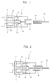
- the optical transceiver of the present embodiment comprises a transmitting section 2 having a device for converting electric signals to optical signals, for example, a light-emitting device 11 including a light-emitting diode and an electric circuit 12 which drives the light-emitting device 11, a receiving section 3 having a device for converting optical signals to electric signals, for example, a photo-detector 13 including a photodiode or a similar device and an electric circuit 14 which amplifies electric signals of the photo-detector 13, and a light conducting type optical distribution element (light conducting type optical divider) 16 for coupling the light-emitting device 11 and the photo-detector 13 to an optical fiber cable, that is, a single core optical fiber cable 15 which connects between communications apparatus disposed in both stations.
- a transmitting section 2 having a device for converting electric signals to optical signals
- a light-emitting device 11 including a light-emitting diode and an electric circuit 12 which drives the light-emitting device
- An outlet 18 is provided on the optical transceiver, and a connector 17 of the single core optical fiber cable 15 is plugged into the outlet 18 (see Fig. 2).
- a light-emitting diode with a center wavelength of approximately 650 nm is used as the light-emitting device 11, and a silicon PIN-type photodiode is used as the photo-detector 13.
- an acrylic plastic optical fiber cable with a total diameter of 1000 ⁇ m including a core portion with a diameter of 980 ⁇ m and a cladding layer may be used as the optical fiber cable 15.
- an optical distribution element which is formed by shaping a multi-core optical fiber cable into Y may be used.
- the optical transceiver 1 is so constructed that one end of a two-way branch of the light conducting type optical distribution element is coupled to the light-emitting device 11, while the other end thereof is coupled to the photo-detector 13, an end of its stem side facing the outlet 18.
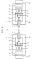
- Fig. 3 shows an example of the light conducting type optical distribution element 16 used in an embodiment of the present invention.
- a multi-core fiber is used as the light conducting type optical distribution element 16.
- the optical fiber 16 is composed so as that a multiplicity of core materials (so-called “core”) 25 for propagating light are bundled up therein, spaces between the core materials 25 being filled up with cladding material (so-called "cladding") 26 having a refractive index difference in a manner of separating each core material.
- core core materials
- cladding cladding material
- each core in the optical fiber 16 is made to propagate light.
- the optical fiber 16 is formed in the Y shape so that one end of the multi-core fiber is split into two ways in the radial direction (Fig. 3B).
- an acrylic multi-core fiber with a core diameter of approximately 50 ⁇ m each, the number of cores 500, and an outer diameter of 1000 ⁇ m is processed and prepared.
- One end of the multi-core fiber approximately 1.5 cm long is cut by knife in the length direction for about 1 cm in a manner of splitting two ways in the radial direction, and the Y shape is formed as shown in Fig. 3B.
- the light conducting type distribution element 16 it is possible to process and fabricate a double core fiber into the Y shape.
- the optical transceiver 1 of the present embodiment it is possible to built in with the Y-shaped light guide optical distribution element 16 consisting essentially of a multi-core fiber. Accordingly, there is no need of installing lenses, prisms or the like, nor adjusting the light axis of each optical section, nor mounting each optical section with fine precision. Further, it can also be made up in a simple structure. Namely, it is possible to bring about an optical transceiver of the single core full two-way duplex communications type in a simple and low-cost construction without requiring a lens, a prism or any other related optical item.
- the Y-shaped light guiding type optical distribution element 16 comprises a multi-core fiber, for example, when signal light from the light-emitting device 11 is incident on the other branch section 22, even if this signal light should reflect the coupled section between the light guiding type optical distribution element 16 and the optical fiber cable 15, the reflected light will not be incident on the other branch section 23 side. Consequently, any reflection of signal light from the light-emitting device 11 reflecting from the coupled section of the optical fiber cable 25 and the signal light from the communications apparatus of the other station being transmitted via the same optical fiber cable 15 will not be mixed, and such a mixed signal will not be incident on the photo-detector 13.
- single outlet 18 in the optical transceiver 1 is sufficient for the connector 17 to connect to the optical fiber cable 15, it is well suited to applications of communications apparatus where not many number of connector outlets can be provided (for instance, including digital apparatus such as digital video cameras and minidisk players).
- the signal-to-noise-intensity ratio necessary for securing the bit error rate (1E-12) is calculated to be approximately 23.0 dB or more when the signal waveform is approximated into a Gaussian distribution.
- retrogressive optical noise is considered to be more dominant than equipment noise such as thermal noise. Accordingly, it is necessary for a signal optical intensity to be sufficiently higher than the retrogressive light level so as to reach the receiver.
- An optical transceiver prepared in accordance with the present embodiment is used to measure its optical signal property according to the configuration shown in Fig. 4. After light is emitted at a predetermined intensity from the light-emitting diode 11 on the transmitting side of an optical transceiver 31 on a station A side, the signal light is transmitted to an optical transceiver 33 on a station B side via a 5m-long optical fiber cable 32 for transmission. In this configuration, the light-emitting diode 11 on the station B side is so arranged that it did not emit light and that only the intensity of receiving light is measured. In such a procedure, the stray optical noise intensity and the intensity of arriving signal of the optical transceiver of an embodiment are measured.
- 35 represents a constant-current power supply connected to the electric circuit 12 which drives the light-emitting diode 11 on the station A side
- 36 and 37 respectively represent the optical power meters connected to electric circuits 14 which amplify the electric signals of photodiodes 11 on the Stations A side and the Station B side.
- the optical intensity from the light-emitting diode 11 on the Station A side is set at approximately -14.0 dBm by adjusting the constant-current power supply 35
- the retrogressive optical noise intensity detected by the photodiode 13 on the Station A side is approximately -39.6 dBm and an arriving signal intensity of approximately -27.9 dBm is detected by the photodiode on the Station B side. Consequently, as the ratio of signal light to noise optical intensity, a performance of approximately 11.7 dB is achieved.
- this optical intensity ratio is converted to the voltage output ratio, approximately 23.4 dB is obtained. It is clear that by using the optical transceiver of the present embodiment, it is fully possible to conduct single core full duplex digital optical communications at a bit error rate of 1E-12.
- Fig. 5 shows an optical communications system of the present invention, namely, an embodiment of the optical communications system provided with the above-mentioned optical transceiver 1.
- An optical communications system 40 in accordance with an embodiment of present invention comprises a plurality of communications apparatus, for example, communications apparatus 50 on one side and communications apparatus 60 on the other side, with a single core optical fiber cable 41 connecting both communications apparatus 50 and 60, so as to perform the two-way full duplex communications via an optical fiber cable 41.
- the communications apparatus 50 on one side comprises the optical transceiver 1 including the transmitting section 2 having the light-emitting device 11 converting electric signals to optical signals and the electric circuit 12 driving the light-emitting device 11, the receiving section 3 having the photo-detector 13 converting optical signals to electric signals and the electric circuit 14 amplifying its electric signals, and the light conducting type optical distribution element 16.
- the transmitting section 2, the receiving section 3 and the light conducting type optical distribution element 16 are integrally built-in the optical transceiver 1.
- the communications apparatus 50 comprises a control circuit 51 which acts as a bridge of electric signals with digital equipment 51 to control the transmitting section 2 and the receiving section 3.
- the communications apparatus 60 on the other side likewise comprises the optical transceiver 1 including the integrally built-in the transmitting section 2 having the light-emitting device 11 converting electric signals to optical signals and the electric circuit 12 driving the light emitting device 11, the receiving section 3 having the photo-detector 13 converting optical signals to electric signals and the electric circuit 14 amplifying its electric signals, and the light conducting type optical distribution element 16, with the further provision of a control circuit 61 which acts as a bridge of electric signals with the digital equipment 51 to control the transmitting section 2 and the receiving section 3.
- a connector 17 is attached respectively to both ends of the optical fiber cable 41, and the connector 17 is plugged in the outlet 18 of the respective optical transceivers 1 in both communications apparatus 50 and 60 thus to be coupled to each of the transmitting section 2 and receiving section 3 via the light conducting type optical distribution element 16.
- Optical transmission of the optical communications system 40 of the present embodiment is carried out as follows.
- the transmitting section 2 is subjected to drive control by the control circuit 51 of the communications apparatus 50, and the light-emitting device 11 is operated by the electric circuit 12 to generate an optical signal which is incident on the optical fiber cable 41 via one branch section of the light conducting type optical distribution element 16.
- This optical signal from the end of the other side of the optical fiber cable 41 being incident on the light conducting type optical distribution element 16 of the communications apparatus 60 on the other side is distributed to be incident on the photo detector 13 of the receiving section 3, then the detected light signal is converted to an electrical signal in the receiving section 3 and outputted.
- an optical signal from the transmitting section 2 of the communications apparatus 60 on the other side via the light conducting type optical distribution element 16 being incident on the optical fiber cable 41 is distributed via the light conducting type optical distribution element 16 of the communications apparatus on one side to be incident on the photo-detector 13, then the detected light signal is converted to an electric signal in the receiving section 3 and outputted.
- the signal-to-noise-intensity ratio may be improved in single core two-way full duplex communications, while, at the same time, the entire construction including the communications apparatus 50 and 60 and connection of the optical fiber cable 41 may be simplified.
- each of the communications apparatus 50 and 60 is provided with an optical transceiver having the built-in, multi-core Y-shaped light conducting type optical distribution element 16, the equipment structure can be simplified. Also, because only one connector outlet 18 for connecting the optical fiber cable 41 suffices, it is possible to simplify handling such as connection of the optical fiber cable 41 to the communications apparatus 50 and 60.
- the optical transceiver may be constructed in a simple structure since the optical transceiver is provided with built-in sections of the transmitting section, the receiving section, and the optical distribution element (optical divider), especially, the multi-core Y-shaped optical divider. This feature makes it possible to produce an optical transceiver of single core full two-way duplex communications marked by the simple and low-cost structure.
- improvement of the signal-to-noise-intensity ratio in single core two-way fully duplex communications in the communication system may be accomplished in addition to a benefit of simplification in the overall construction including connection of an optical fiber cable to the communications apparatus.
Landscapes
- Physics & Mathematics (AREA)
- Electromagnetism (AREA)
- Engineering & Computer Science (AREA)
- Computer Networks & Wireless Communication (AREA)
- Signal Processing (AREA)
- Optical Couplings Of Light Guides (AREA)
- Optical Communication System (AREA)
Applications Claiming Priority (2)
| Application Number | Priority Date | Filing Date | Title |
|---|---|---|---|
| JP2000331399A JP2002139659A (ja) | 2000-10-30 | 2000-10-30 | 光通信システム、通信機器及び光トランシーバ |
| JP2000331399 | 2000-10-30 |
Publications (1)
| Publication Number | Publication Date |
|---|---|
| EP1202480A2 true EP1202480A2 (de) | 2002-05-02 |
Family
ID=18807746
Family Applications (1)
| Application Number | Title | Priority Date | Filing Date |
|---|---|---|---|
| EP01124902A Withdrawn EP1202480A2 (de) | 2000-10-30 | 2001-10-18 | Bidirektionales faseroptisches Übertragungvorrichtung, Übertragungsgerät und optischer Sender-Empfänger |
Country Status (4)
| Country | Link |
|---|---|
| US (1) | US20020164115A1 (de) |
| EP (1) | EP1202480A2 (de) |
| JP (1) | JP2002139659A (de) |
| CA (1) | CA2359271A1 (de) |
Cited By (4)
| Publication number | Priority date | Publication date | Assignee | Title |
|---|---|---|---|---|
| DE102008004224A1 (de) * | 2008-01-14 | 2009-07-23 | Avago Technologies Fiber Ip (Singapore) Pte. Ltd. | Elektro-optische Datenübertragungsanordnung sowie Verfahren zur deren Konfiguration |
| WO2011056339A1 (en) * | 2009-11-05 | 2011-05-12 | The Boeing Company | Transceiver for plastic optical fiber networks |
| CN102075253A (zh) * | 2010-12-30 | 2011-05-25 | 刘新田 | 铁路区间光通话柱 |
| US9105790B2 (en) | 2009-11-05 | 2015-08-11 | The Boeing Company | Detector for plastic optical fiber networks |
Families Citing this family (10)
| Publication number | Priority date | Publication date | Assignee | Title |
|---|---|---|---|---|
| US7327959B2 (en) | 2001-12-17 | 2008-02-05 | Telecast Fiber Systems, Inc. | Camera-mountable fiber optic transceiver system |
| JP4581636B2 (ja) * | 2004-11-10 | 2010-11-17 | 富士ゼロックス株式会社 | 光信号伝送装置と、光信号伝送装置を用いた光信号伝送システム |
| FR2900413B1 (fr) * | 2006-04-28 | 2008-06-13 | Seppic Sa | Nouveau procede d'amelioration des proprietes moussantes de formulations nettoyantes et/ou moussantes a usage topique |
| US7693374B2 (en) * | 2006-05-11 | 2010-04-06 | Corning Cable Systems Llc | Tools and methods for manufacturing fiber optic distribution cables |
| JP5214286B2 (ja) * | 2008-03-12 | 2013-06-19 | 旭化成イーマテリアルズ株式会社 | 光分岐結合器、光分岐結合器の製造方法及び単芯双方向通信装置 |
| JP5390614B2 (ja) * | 2008-08-26 | 2014-01-15 | ナイス・ネットワークス・インコーポレイテッド | ケーブル分離機能を一体化した光ファイバー・ケーブル用コネクタ |
| FR2978315B1 (fr) * | 2011-07-20 | 2013-09-13 | Thales Sa | Reseau de transmission d'informations et noeud de reseau correspondant |
| WO2013157245A1 (ja) * | 2012-04-20 | 2013-10-24 | 日本電気株式会社 | 多重光伝送路、光伝送システムおよび光伝送方法 |
| JP6241056B2 (ja) * | 2013-04-12 | 2017-12-06 | 三菱ケミカル株式会社 | 多重信号伝送用光伝達媒体、多重信号伝送装置、および多重信号伝送方法 |
| US20150341113A1 (en) * | 2014-05-20 | 2015-11-26 | The Boeing Company | Lighting and data communication system using a remotely located lighting array |
-
2000
- 2000-10-30 JP JP2000331399A patent/JP2002139659A/ja active Pending
-
2001
- 2001-10-18 EP EP01124902A patent/EP1202480A2/de not_active Withdrawn
- 2001-10-18 CA CA002359271A patent/CA2359271A1/en not_active Abandoned
- 2001-10-23 US US10/044,662 patent/US20020164115A1/en not_active Abandoned
Cited By (8)
| Publication number | Priority date | Publication date | Assignee | Title |
|---|---|---|---|---|
| DE102008004224A1 (de) * | 2008-01-14 | 2009-07-23 | Avago Technologies Fiber Ip (Singapore) Pte. Ltd. | Elektro-optische Datenübertragungsanordnung sowie Verfahren zur deren Konfiguration |
| US7654751B2 (en) | 2008-01-14 | 2010-02-02 | Avago Technologies Fiber Ip (Singapore) Pte. Ltd. | Electro-optical data transmission arrangement, as well as method for its configuration |
| DE102008004224B4 (de) * | 2008-01-14 | 2017-05-11 | Avago Technologies General Ip (Singapore) Pte. Ltd. | Elektrooptische Datenübertragungsanordnung sowie Verfahren zu deren Konfiguration |
| WO2011056339A1 (en) * | 2009-11-05 | 2011-05-12 | The Boeing Company | Transceiver for plastic optical fiber networks |
| US8983302B2 (en) | 2009-11-05 | 2015-03-17 | The Boeing Company | Transceiver for plastic optical fiber networks |
| US9105790B2 (en) | 2009-11-05 | 2015-08-11 | The Boeing Company | Detector for plastic optical fiber networks |
| CN102075253A (zh) * | 2010-12-30 | 2011-05-25 | 刘新田 | 铁路区间光通话柱 |
| CN102075253B (zh) * | 2010-12-30 | 2013-08-21 | 刘新田 | 铁路区间光通话柱 |
Also Published As
| Publication number | Publication date |
|---|---|
| CA2359271A1 (en) | 2002-04-30 |
| US20020164115A1 (en) | 2002-11-07 |
| JP2002139659A (ja) | 2002-05-17 |
Similar Documents
| Publication | Publication Date | Title |
|---|---|---|
| US4301543A (en) | Fiber optic transceiver and full duplex point-to-point data link | |
| JP3521111B2 (ja) | 単一ファイバ双方向データリンク | |
| US6909821B2 (en) | Network for distributing signals to a plurality of users | |
| JP7294787B2 (ja) | 双方向多波長ギガビット光ファイバネットワーク | |
| US4317614A (en) | Fiber optic bus manifold | |
| US7400801B1 (en) | Bidirectional HDCP module using single optical fiber and waveguide combiner/splitter | |
| US20020164115A1 (en) | Optical fiber communication system, communications apparatus and optical transceiver | |
| US4955014A (en) | Broadband optical communication system, particularly in the subscriber area | |
| CA2590459C (en) | Point-to-point optical fibre link | |
| EP1001292B1 (de) | Übertragungssystem mit polymeren optischen Fasern | |
| WO2014086393A1 (en) | Optical receiver and method for receiving optical signals | |
| US20140217270A1 (en) | Light-receiving module | |
| US6219477B1 (en) | Multiport single path optical system and associated method | |
| US20040161240A1 (en) | Module having two bi-directional optical transceivers | |
| JP2000147333A (ja) | 光ファイバ用コネクタとこれを利用した光送受信装置 | |
| Jacobs et al. | Communications: Optical transmission of voice and data: Bandwidth and noise immunity are up; size, weight, and costs are down | |
| JPH10227928A (ja) | 並列光伝送装置及び並列光伝送方式 | |
| EP1018814A2 (de) | Vorrichtung zur optischen Übertragung | |
| EP1250772B1 (de) | Netzwerk zur verteilung von signalen an eine vielzahl von benutzern | |
| US5894534A (en) | Fiber optic "T" coupler single path transceiver | |
| US6259839B1 (en) | Optical communication connector | |
| Hanson | Fiber optics in local area network applications | |
| KR100698601B1 (ko) | 광선로 거리 측정 장치 | |
| JP2003294961A (ja) | 光通信器検査装置 | |
| Geckeler | FIBRE-OPTICAL COMMUNICATION IN COMPUTER SYSTEMS |
Legal Events
| Date | Code | Title | Description |
|---|---|---|---|
| PUAI | Public reference made under article 153(3) epc to a published international application that has entered the european phase |
Free format text: ORIGINAL CODE: 0009012 |
|
| AK | Designated contracting states |
Kind code of ref document: A2 Designated state(s): AT BE CH CY DE DK ES FI FR GB GR IE IT LI LU MC NL PT SE TR |
|
| AX | Request for extension of the european patent |
Free format text: AL;LT;LV;MK;RO;SI |
|
| STAA | Information on the status of an ep patent application or granted ep patent |
Free format text: STATUS: THE APPLICATION HAS BEEN WITHDRAWN |
|
| 18W | Application withdrawn |
Effective date: 20031211 |