EP1202557A2 - Drucksystem und -verfahren - Google Patents
Drucksystem und -verfahren Download PDFInfo
- Publication number
- EP1202557A2 EP1202557A2 EP01125057A EP01125057A EP1202557A2 EP 1202557 A2 EP1202557 A2 EP 1202557A2 EP 01125057 A EP01125057 A EP 01125057A EP 01125057 A EP01125057 A EP 01125057A EP 1202557 A2 EP1202557 A2 EP 1202557A2
- Authority
- EP
- European Patent Office
- Prior art keywords
- dot
- pattern
- output
- representative color
- dot patterns
- Prior art date
- Legal status (The legal status is an assumption and is not a legal conclusion. Google has not performed a legal analysis and makes no representation as to the accuracy of the status listed.)
- Withdrawn
Links
- 238000000034 method Methods 0.000 title claims abstract description 35
- 239000003086 colorant Substances 0.000 claims abstract description 59
- 238000010438 heat treatment Methods 0.000 claims description 6
- 238000004364 calculation method Methods 0.000 claims description 4
- 238000012545 processing Methods 0.000 abstract description 70
- 238000006243 chemical reaction Methods 0.000 abstract description 64
- 230000000873 masking effect Effects 0.000 abstract description 11
- 238000012937 correction Methods 0.000 abstract description 8
- 239000000976 ink Substances 0.000 description 43
- 238000010586 diagram Methods 0.000 description 16
- 238000005259 measurement Methods 0.000 description 11
- 239000007788 liquid Substances 0.000 description 9
- 239000007787 solid Substances 0.000 description 8
- 238000013139 quantization Methods 0.000 description 7
- 230000008707 rearrangement Effects 0.000 description 6
- 230000005540 biological transmission Effects 0.000 description 5
- 230000000694 effects Effects 0.000 description 5
- 238000009835 boiling Methods 0.000 description 3
- 230000010365 information processing Effects 0.000 description 3
- 230000008569 process Effects 0.000 description 3
- 230000008901 benefit Effects 0.000 description 2
- 230000015556 catabolic process Effects 0.000 description 2
- 238000007906 compression Methods 0.000 description 2
- 230000006835 compression Effects 0.000 description 2
- 238000007796 conventional method Methods 0.000 description 2
- 238000006731 degradation reaction Methods 0.000 description 2
- 230000006870 function Effects 0.000 description 2
- 238000012986 modification Methods 0.000 description 2
- 230000004048 modification Effects 0.000 description 2
- 238000003672 processing method Methods 0.000 description 2
- 238000011084 recovery Methods 0.000 description 2
- 230000004044 response Effects 0.000 description 2
- 230000007480 spreading Effects 0.000 description 2
- 230000002411 adverse Effects 0.000 description 1
- 238000013459 approach Methods 0.000 description 1
- 230000015572 biosynthetic process Effects 0.000 description 1
- 230000008859 change Effects 0.000 description 1
- 238000004140 cleaning Methods 0.000 description 1
- 239000012141 concentrate Substances 0.000 description 1
- 239000000470 constituent Substances 0.000 description 1
- 238000010276 construction Methods 0.000 description 1
- 238000013144 data compression Methods 0.000 description 1
- 238000004042 decolorization Methods 0.000 description 1
- 238000001514 detection method Methods 0.000 description 1
- 230000002708 enhancing effect Effects 0.000 description 1
- 238000001704 evaporation Methods 0.000 description 1
- 230000008020 evaporation Effects 0.000 description 1
- 238000013507 mapping Methods 0.000 description 1
- 230000003287 optical effect Effects 0.000 description 1
- 230000035515 penetration Effects 0.000 description 1
- 230000002093 peripheral effect Effects 0.000 description 1
- 230000009467 reduction Effects 0.000 description 1
- 230000000717 retained effect Effects 0.000 description 1
- 230000035945 sensitivity Effects 0.000 description 1
- 239000000126 substance Substances 0.000 description 1
- 238000012360 testing method Methods 0.000 description 1
- 230000000007 visual effect Effects 0.000 description 1
Images




Classifications
-
- H—ELECTRICITY
- H04—ELECTRIC COMMUNICATION TECHNIQUE
- H04N—PICTORIAL COMMUNICATION, e.g. TELEVISION
- H04N1/00—Scanning, transmission or reproduction of documents or the like, e.g. facsimile transmission; Details thereof
- H04N1/46—Colour picture communication systems
- H04N1/52—Circuits or arrangements for halftone screening
Definitions
- the present invention relates to a printing apparatus for and a printing method of forming pixels with dot patterns and more specifically to image processing in a printing apparatus that performs a so-called multipass printing in which the same line is printed in a plurality of scanning operations of a print head each using different nozzles.
- a well-known printer image processing method is an image processing technique based on a color halftone model.
- Fig. 13 is a block diagram showing an example of a conventional image processing unit used in a printer.
- Image data in the form of an RGB signal is input from an input terminal 101, converted into a resolution level compatible with that of the printer by a resolution conversion unit 102, and then converted into a CMY density signal for each pixel by a density conversion unit 103.
- the image data, after being converted from the RGB signal into the CMY density signal, is further converted by a black generation unit 104 into a density signal that includes a black density signal K.
- the image data now in the form of a CMYK density signal is subjected to under color removal processing and masking in a masking/UCR unit 105 whereby the image data is converted into a halftone area signal, a CMYK density signal that has its crosstalk component compensated for.
- the image data in the form of the halftone area signal is ⁇ -corrected by an output ⁇ correction unit 106 to compensate for a linearity between the halftone area signal and the output density as by dot gain processing.
- the image data is converted into binary data (referred to also as "bit map data") for each color component by a binarization unit 107 and is output from a host side interface unit 108 to a transmission line 201.
- the bit map data transmitted from the host side interface unit 108 is taken into the printer through a printer side interface unit 109. Further, in an H-V conversion unit 110 the bit map data has its output order converted in accordance with a driving order of a print head.
- a mask generation unit 111 generates a thinning pattern (mask data) for multipass printing and gives it to a head driver 112, which in turn thins the converted bit map data according to the mask data from the mask generation unit 111. Based on the thinned bit map data, the print head 113 is driven to eject ink during each of the scans with a paper feed operation performed between the scans. An image is thus formed by multipass printing.
- the multipass printing involves dividing the bit map data for the same scan line into a plurality of parts and performing a plurality of passes and a predetermined amount of paper feed between the individual passes to eject ink from different nozzles of the print head in each of the passes according to the divided bit map data for the same scan line, thus forming an image for the same line.
- This multipass printing can reduce unevenness in printing due to dot landing deviations, variations in ink ejection volume and ink penetration time differences.
- the density conversion unit 103 and the output ⁇ correction unit 105 are normally integrated into a lookup table (LUT), rather than being provided individually with processing circuits and software. This arrangement can shorten the processing time.
- LUT lookup table
- the memory capacity required for the H-V conversion increases as the printer resolution and the width that can be printed in one pass increase or, in a more general term, as the number of nozzles in the print head increases. This gives rise to another problem that when the resolution is enhanced, the memory capacity required for processing increases in proportion to the square of the resolution.
- high-resolution printers tend to have an increased number of nozzles integrated in the print head and make ink droplets ejected from these nozzles smaller to reduce dot diameters and thereby realize higher resolutions. Since the ink droplets ejected from the nozzles of such a print head are very small, dot position variations due to landing deviations are apt to become large relative to the dot diameter. Thus even the multipass printing described above may not be able to eliminate image quality degradations caused by printing variations. Further, the multipass printing often uses a checker pattern as the mask pattern in the mask processing. When such a mask pattern is used, problems may arise in which dots that need to be printed fail to be printed or dot printing concentrates on a particular pass.
- the present invention has been accomplished in light of the problems described above and it is an object of the present invention to provide a printing system and a printing method with a low cost and a reduced processing time and with a capability to take full advantage of features of the multipass printing.
- the present invention provides a printing system, which uses a print head having a plurality of print elements, performs a plurality of scan operations of the print head over the same area, and allocates different print elements to each of the plurality of scans for printing, the printing system comprising: a code table from which to output representative color codes based on input color data; and a pattern generation means for generating dot patterns of the representative color codes according to a correspondence between the input color data and the representative color codes; wherein the dot pattern generation means stores the dot patterns and outputs in each of the plurality of scans the associated dot pattern.
- the present invention provides a printing method, which uses a print head having a plurality of print elements, performs a plurality of scan operations of the print head over the same area, and allocates different print elements to each of the plurality of scans for printing, the printing method comprising the steps of: outputting representative color codes from a code table based on input color data; and generating dot patterns of the representative color codes according to a correspondence between the representative color codes and the dot patterns: wherein the step of generating the dot patterns outputs in each of the plurality of scans the associated dot pattern.
- the processing time can be shortened by replacing the image data with dot patterns of the representative color codes before printing.
- Fig. 1 is a block diagram showing an image processing unit according to the present invention.
- Fig. 2 is a diagram showing the structure of a code table.
- Fig. 3 is a conceptual diagram showing a hue among cyan, magenta and yellow.
- Fig. 4 is a diagram showing structure of an output density table.
- Fig. 5 is a diagram showing the structure of a pattern table.
- Fig. 6A is a diagram showing the structure of a dot pattern 1 and Fig. 6B is a diagram showing the structure of a dot pattern 2.
- Fig. 7A illustrates bit map data before being divided and Fig. 7B illustrates the structures of dot patterns divided into 2-pass printing.
- Fig. 8 is a block diagram showing another example of the image processing unit.
- Fig. 9 is a block diagram showing still another example of the image processing unit.
- Fig. 10A illustrates bit map data before being divided and Fig. 10B illustrates the structure of dot patterns divided into 2-pass printing.
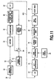
- Fig. 11 is a block diagram showing a further example of the image processing unit.
- Fig. 12A illustrates bit map data before being divided and Fig. 12B illustrates the structures of dot patterns divided into 2-pass printing.
- Fig. 13 is a block diagram showing a conventional image processing unit.
- Fig. 1 is a block diagram showing an image processing system as one embodiment of this invention.
- the image processing system comprises a system on the host side and a system on the printer side.
- the host side system comprises an input terminal 10, a density conversion unit 11, an addition unit 12, a spread processing unit 13, a subtraction unit 14, a limiter 15, a quantization unit 16, an output density table 17, a representative color code conversion unit 18, and a host side interface unit 19.
- the printer side system comprises a printer side interface unit 20, an H-V conversion unit 21, a pattern conversion unit 22, a selector 24, a pass control unit 25, a rearrangement unit 26, a head driver 27, and a print head 28.
- dots that are actually formed are output at a resolution of 1200 dpi (dots per inch).
- one pixel is formed by using a 4 ⁇ 4-dot pattern.
- 4 ⁇ 4 dots are treated as one unit and referred to also as a "block.”
- the processing performed on the host side from the input terminal 10 to the host side interface unit 19 is actually executed as printer driver's processing.
- a rough flow of processing in the image processing system of the above construction is as follows.
- image data in the form of an RGB signal is entered into the input terminal 10 for each pixel.
- the image data is converted into a CMY density signal by the density conversion unit 11. It is assumed here that the CMY density signal does not exceed the reproduction range of a representative color described later.
- the addition unit 12 adds an error signal.
- the image data which is added the error signal then is limited by the limiter 15 to prevent a possible gray scale inversion.
- the limited image data is quantized by the quantization unit 16.
- the image data for each pixel which consists of 8 bits in each CMY color is quantized into image data with four bits in each color by discarding the lower four bits of the data.
- the quantization is not limited to this method and other methods, such as rounding the lower four bits, may be used.
- the representative color code conversion unit 18 converts the quantized CMY 4-bit image data into a representative color code that corresponds to this data.
- 256 different colors uniformly distributed in a predetermined color space are selected as “representative colors” in advance. These representative colors are assigned “representative color codes” for identification.
- color data a combination of each CMY four-bit data, is matched with a representative color code whose color is closest to the one presented by the color data.
- This match or correspondence is set in a code table 181 (see Fig. 2) in the representative color code conversion unit 18. That is, by referencing the code table 181 through an address based on the CMY 4-bit image data entered into the representative color code conversion unit 18, the corresponding representative color code can be determined.
- the representative color code thus determined is sent from the host side to the printer side. That is, the representative color code is output from the host side interface unit 19 through the transmission line 201 of a printer cable to the printer side interface unit 20 and the H-V conversion unit 21.
- errors produced as a result of coding the image data are processed by the spread processing unit 13 and others and the detail of the error processing will be explained later.
- the structure of the code table 181 and the representative color will also be detailed later.
- the H-V conversion unit 21 changes the order in which the representative color code data received is to be read out, according to the arrangement of the ink ejection nozzles in the print head. That is, the H-V conversion unit 21 converts raster data sent from the host side for each line into data that corresponds to the nozzle arrangement of the print head, changing the horizontally arranged data into vertically arranged data.
- the pattern conversion unit 22 outputs the dot pattern data corresponding to the entered representative color code as the print head makes each pass in the multipass scan operation. That is, the pattern conversion unit 22 has pattern tables 22a, 22b (see Fig. 6) each of which contains blocks of dot pattern data for each YMC color that correspond to respective representative color codes. These pattern tables 22a, 22b contain dot patterns for each of two passes in the multipass printing of this embodiment as described later. The structure of the pattern tables and the multipass printing based on the pattern tables will be detailed with reference to Fig. 6 and Fig. 7.
- the selector 24 selects and outputs the dot patterns from the pattern table specified by a control signal from the pass control unit 25. In this way, in the multipass printing consisting of two passes, it is possible to output the dot patterns that correspond to each pass.
- the rearrangement unit 26 rearranges the dot patterns in the order in which they are to be output from the print head 28.
- the head driver 27 according to the rearranged dot patterns drives the print head 28 for printing.
- the conversion into the output dot patterns by the pattern conversion unit 22 and the rearrangement into the head drive data by the rearrangement unit 26 are performed in synchronism with a head drive signal.
- the CMYK heads are spaced a predetermined distance from each other in many printing apparatus.
- the processing performed in and following the H-V conversion unit 21 is executed for each color independently. That is, the tables in the pattern conversion unit 22 are provided for each color, and for each representative color code entered, dot patterns, one for each C, M, Y and K, are output successively in synchronism with the head drive signal.
- the output density table 17 stores colors reproduced by the printer of this embodiment, i.e., density data for Y, M, C which are obtained by printing dot patterns corresponding to the representative color code, as will be described with reference to Fig. 4.
- the output density table 17 outputs the reproduced color data corresponding to the representative color code entered from the representative color code conversion unit 18.
- the density data of each of Y,M,C can be obtained by such techniques as optical density detection and color measurement.
- the subtraction unit 14 determines a difference between the reproduced color and the input color, i.e., calculates an error of the output density with respect to the input density for each of Y, M and C.
- the spread processing unit 13 generates error signals for surrounding pixels to spread the error over the surrounding pixels by a known error spreading method. The error signals thus generated are added to the image data by the addition unit 12 as described earlier.
- the input image data is processed to perform the 2-pass printing using the print head 28.
- the image processing using the representative color code enables the color processing, ranging from the conventional density conversion to the output ⁇ correction as described with reference to Fig. 13, and the successive binarization processing to be performed integrally.
- the representative color code and the representative color will be described in more detail in the following.
- the representative colors are selected in advance from among colors uniformly distributed in a predetermined color space.
- the data processing for each pixel to print C, M, Y, K dot patterns of 1200 dpi is performed using 300 ppi coordinates.
- the dot pattern has 4x4 dots for each pixel.
- an 8-bit representative color code is used.
- the number of colors that can be perceived by humans is significantly small.
- the following method is used in selecting representative colors and replacing the input image data with the selected representative colors to reduce the number of colors for use in image formation and compress the image data. Because the image data can be compressed in this way, the volume of data transmitted over the transmission line 201 can be reduced. This can not only shorten the transmission time but greatly reduce the memory capacity required by the H-V conversion unit 21.
- the representative colors may be selected in the following two methods.
- a first method involves printing patches of all possible dot patterns on the printer with a 4 ⁇ 4-dot block shown in Fig. 5 taken as a unit, measuring the colors of the printed patches of each pattern, and selecting, as representative colors from among all the measured dot patterns, those colors that are uniformly distributed in a predetermined color space (for example, an input CMY space and an L*a*b* space).
- a predetermined color space for example, an input CMY space and an L*a*b* space.
- a second method involves modeling a relation between the dot patterns and the colors formed by printing the dot patterns, calculating the colors corresponding to all dot patterns, and selecting as representative colors those colors that are uniformly distributed in a predetermined color space.
- the number of patterns is reduced by placing a limitation on the number of mixed colors and by eliminating those patterns that are found identical through rotation and mirroring of images.
- the known modeling using, for example, a color halftone model is performed to further reduce the number of patterns down to a level where the color measurements of the available patterns are feasible.
- the patches being printed and actually measured in the same way as the first method.
- those colors uniformly distributed in a predetermined space color are selected as representative colors.
- some limitations may be imposed which include eliminating those dot patterns with large measurement variations as unstable patterns and preventing those patterns of sparsely distributed dots from being removed in order to alleviate the granularity of highlight areas.
- a test pattern is printed for each combination of overlapping ink colors and measured in advance to determine a density (hereinafter referred to as an "assessment value") for each combination of overlapping inks. Further, by taking statistics of dots the printer forms on a print medium, an equivalent dot diameter is determined for each ink.
- an area ratio of each combination of overlapping inks to each dot pattern is determined from the equivalent dot diameter of the ink, the dot pitch determined from the resolution, and the dot arrangement in the dot pattern.
- a product of the area ratio and the assessment value for each combination of overlapping inks is calculated and a sum of these products in each dot pattern is taken to be a reproduced color value of the dot pattern.
- a difference is taken between the reproduced color values of different dot patterns. If a combination of dot patterns is found for which this difference is less than a predetermined level ( ⁇ E), one of the dot patterns whose density is lower, i.e., whose reproduced color value is smaller, is removed from the candidates for the representative colors. This process is repeated.
- ⁇ E predetermined level
- the value of the predetermined level ( ⁇ E) is increased and the above-described process is repeated until the number of representative color candidates falls below the predetermined number.
- the representative colors are determined in this manner.
- the representative colors are matched to their 4 ⁇ 4-dot patterns.
- Fig. 5 shows the correspondence between the representative color codes generated by the representative color code conversion unit 18 (see Fig. 1) and the dot patterns for each of C, M, Y, K colors. As shown in the figure, the selected 256 representative color codes are matched to dot patterns for each CMYK color. Printing these patterns produce the corresponding representative colors.
- the representative color codes are output from the representative color code conversion unit 18 for each input color data C, M, Y. That is, the code table 181 of the representative color code conversion unit 18 assigns the color represented by four bits of each CMY with a representative color code that should be output. Each of the CMY colors has 16 possible representations and thus a total of 16 ⁇ 16 ⁇ 16 different color representations is possible.
- Fig. 2 and Fig. 3 illustrate a concept of the code table 181. The position of each lattice point in a cubic lattice is represented by the four bits for each of C, M, Y. The representative color codes are mapped in these lattice point.
- the mapping of the representative color code in the code table is performed as follows. First, the 4-bit density data for C, M, Y representing a lattice point are converted into quantized representative values.
- the quantized representative value is produced by a conversion formula of "sum of weight of each bit + quantization step/2" which converts a 4-bit value into an 8-bit value.
- the lattice point which is converted into quantized representative values is expressed as x(C', M', Y'). This method is used because, in processing the input data, the conversion is done by the quantization unit 16 by discarding the lower four bits of the input image data. If the quantization unit 16 performs rounding rather than omitting the lower four bits, a value with the lower four bits set to 0 may be used.
- a representative color is determined which corresponds to a value a for which the distance r determined above is minimum. This representative color is taken as the representative color code that is to be mapped in the lattice point.
- An error represented as the distance r is spread over the adjoining pixels by the spread processing unit 13 using the conventionally known error spreading method.
- the square of the distance between the color measurement value of the representative color and the quantized representative color is determined, it is also possible to determine an absolute value of the distance and then determine a representative value for which this absolute value is minimum.
- the quantized representative value uses a center value of the quantized value, it is not limited to the center value.
- the quantized representative value may be a wholly or partly shifted value.
- the CMY signal after quantization may be used as the code.
- Fig. 4 conceptually illustrates the output density table 17 of this embodiment.
- the output density table 17 matches a representative color code to a combination of 8-bit CMY densities.
- the density data to be stored in this table can be determined as follows. First, patches of a dot pattern corresponding to each representative color as shown in Fig. 5 are output on the printer of this embodiment and the color measurement is made of these patches. In this color measurement patch positions are separated from each other, and two or more measurements are taken and averaged. Then, the average measurement values (X, Y, Z) are substituted into the following equation to convert them into an RGB signal in an NTSC space.
- R (1.910X - 0.532Y - 0.288Z)/100
- G (-0.985X + 1.999Y - 0.028Z)/100
- B (0.058X - 0.118Y - 0.898Z)/100
- the measured value obtained through conversion as described above is stored at an address of the corresponding representative color code in the output density table 17.
- the method of conversion into the input color space uses a log function for conversion into the RGB density, it is not limited to this example but may use LUT.
- this can be achieved by counter-correcting the value to be stored in the output density table 17.
- the value of the reproduction color data is shifted slightly at a time toward the outside of the color reproduction range of the printer so that the reproduction color data encloses the color reproduction range in the input color space.
- the reproduced CMY colors for blank(white) are all set to 0.
- the pattern tables 1 and 2 in the pattern conversion unit 22 comprise, as described earlier, representative color codes and their corresponding dot patterns. Printing is done according to the dot patterns as described above.
- the print data is conventionally thinned by a predetermined mask pattern for each pass. Because the thinning is done in units of dots, in areas where the density is low there is a possibility that the thinning (mask) pattern and the print pattern may interfere with each other, resulting in the number of printed dots becoming uneven between the passes.
- this embodiment prepares the same number of pattern tables as that of the passes and stores these pattern tables by relating them with the respective passes.
- the dot patterns are output according to the representative color codes stored in the pattern table associated with the current pass being executed, thus printing an image based on this dot pattern data.
- Fig. 5 shows the correspondence between the representative color codes and the dot patterns before the pattern table is divided.
- Dot patterns for four CMYK colors are each matched with a representative color code.
- the dot patterns shown in the figure are each divided into two dot patterns of Fig. 6A and Fig. 6B.
- the dot division is performed by ensuring that the necessary dots are divided into both pattern tables.
- simply dividing the cyan and magenta patterns into two tables according to the checker pattern will result in the dots being heavily allocated only to one table.
- This embodiment therefore, takes steps to ensure that the dots are equally divided between the two pattern tables 22a (see Fig. 6A) and 22b (Fig. 6B).
- the dot outputs from the two tables in principle do not overlap.
- the dot output is set so that several dots overlap each other. That is, the total number of dots in the two pattern tables 22a, 22b associated with the representative color code 255 is 20, which is larger than the total number of dots of 16 before the pattern table is divided. This means that several dots in the block overlap between the first pass and the second pass. This is done to increase the density of solid black.
- the image processing is performed in this way using the code table 181, output density table 17 and pattern tables 22a, 22b prepared in advance to perform the multipass printing. Next, the process of printing will be explained. In this embodiment the multipass printing is adopted.
- Fig. 7 shows a concept for the multipass printing according to this embodiment.
- Fig. 7A shows bit map data before being divided.
- the bit map data is printed in two passes, so the print data is divided according to the representative color codes into two print data, as shown at top left and bottom left in Fig. 7B, by the pattern conversion unit 22.
- the dot pattern division is made in such a way that the output is produced every other dot and not produced at the last column with respect to the direction of main scan.
- the dot diameter is set to about two times the dot pitch, and when the number of output dots in the 4 ⁇ 4-dot block is 8 or less, the pattern table 22B (dot pattern 2 in Fig. 6) is set to blank. This step is taken to eliminate possible degradations of print quality that may be caused by landing deviations and paper feed errors.
- the selector 24 uses an output from the pattern table 22a (see Fig. 6A) when the number is "1" and an output from the pattern table 22b (see Fig. 6B) when the number is "2.” Each square in the figure represents one block.
- the final print output is an image produced by combining a top right pattern and a bottom right pattern of Fig. 7B. Although the final print output image differs from the original bit map data, the adverse effects from the landing deviations are alleviated because the dot diameter is set to about two times the dot pitch and the blocks in an intermediate-to-low-density range where density variations appearing as lines become conspicuous are output in a single pass.
- the mask block is formed 4 ⁇ 4-dot, such that has a resolution of 300 dpi. Therefore, dots in one block within 300 dpi are formed in one pass. Hence, the printing unevenness that occurs within the one block of 300 dpi is mostly attributable to the head characteristic alone and thus corrected by the 300-dpi mask block.
- the dot density of the dot pattern in the vertical direction is increased, such as code "254" or "255" in Fig 6A and 6B.
- the output density table 17 uses values actually measured during the multipass printing, so that the density deviations caused by differing dot patterns are corrected each time the output density table 17 is updated.
- the conventionally performed processing such as resolution conversion, masking/UCR conversion and output ⁇ correction, can be integrated into a simple arrangement.
- the code table 181 is generated based on the output density table 17 that is obtained by measuring the colors of patches, so the black generation processing does not need to be executed independently, thus reducing the processing time compared with the conventional arrangement.
- the scan speed in the main scan direction can be doubled.
- Fig. 8 shows a block diagram of a second embodiment of the image processing system according to the present invention.
- the configuration on the host side is the same as that of the embodiment 1, whereas on the printer side the pattern tables used in the pattern conversion unit 23 following the H-V conversion unit 21 differ from those of the embodiment 1.
- the selector 29 there is provided a blank interpolation unit 30 before the rearrangement unit 26.
- the pattern tables 23a, 23b omit those dots that are always blank in the pattern tables 22a, 22b of the embodiment 1. By removing blank dots the capacity of the pattern tables can be reduced.
- the pattern conversion unit 23 converts the input representative color code into an output dot pattern associated with the pass by using the pattern tables 23a, 23b.
- the selector 29, according to a control signal from the pass control unit 25, selects one dot pattern from the outputs of the pattern tables 23a, 23b.
- the blank interpolation unit 30, according to the control signal from the pass control unit 25, adds blanks omitted from the pattern tables 23a, 23b to the dot pattern entered from the selector 29, thus generating a dot pattern of normal size.
- the processing following the interpolation of blanks is similar to that of the embodiment 1 and thus its explanation is omitted.
- the pattern table 22a leaves even-numbered columns always blank and the pattern table 22b leaves the right end column always blank.
- the pattern table 23a stores data of the pattern table 22a removed of the even-numbered columns
- the pattern table 23b stores data of the pattern table 22b removed of the right end column.
- This embodiment performs a mask-based thinning for each printing pass without using pattern tables.
- Fig. 9 shows a block diagram of the image processing system according to this embodiment.
- the host side has the same configuration as that of the embodiment 1, whereas on the printer side a mask processing unit 31 and a mask generation unit 32 are provided following the H-V conversion unit 21 and a pattern processing unit 33 is provided after the mask processing unit 31.
- the mask generation unit 32 generates a thinning pattern (also referred to as mask data) associated with the current output pass in units of blocks at 300 dpi and supplies the thinning pattern to the mask processing unit 31.
- the mask processing unit 31 masks the representative color code output from the H-V conversion unit 21 with the mask pattern of the mask generation unit 32. In this embodiment, because the representative color code for the blank is set to 0, the representative color codes for the blocks that need to be masked are replaced with 0.
- the pattern processing unit 33 stores dot patterns for the representative colors and converts the representative color code output from the mask processing unit 31 into the associated dot pattern. Then, this dot pattern is printed.
- the number of mask patterns generated by the mask generation unit 32 corresponds to the number of passes.
- Fig. 10 shows a concept of the multipass printing according to this embodiment.
- masking is done in units of 4 ⁇ 4-dot blocks, as described earlier.
- Fig. 10A shows bit map data for a final image to be formed.
- this bit map data is printed in two passes, the masking is done by using two mask patterns shown at top left and bottom left in Fig. 10B.
- a final image formed is a combination of a top right pattern and a bottom right pattern in Fig. 10B.
- the mask has a resolution of 300 dpi and dots within 300 dpi are formed in one and the same pass.
- the printing unevenness that occurs within the 300 dpi is mostly attributable to the head characteristic alone.
- the printing variations due to mechanical accuracy occur concentratedly at the boundary of 300 dpi and are distributed over an entire image, so the printing variation sensitivity with respect to the mechanical accuracy increases as the dot diameter approaches 300 dpi.
- the mask processing unit 31 can be built by taking a logical product(AND) of the representative color code and the mask pattern. If the representative color codes for the blanks are all set to "1," the mask processing unit 31 can be formed by taking a logical sum(OR).
- the masking is done in units of blocks, interferences (beats) between the mask pattern and the bit map, often experienced with the conventional system, do not easily occur.
- interferences beats
- the pattern shown at the left in Fig. 10 is masked with a checker pattern or reversed check pattern in units of dots, there is a possibility that a pattern may be produced which causes the dots to appear concentratedly on only a particular pass or which eliminates the dots that need to be printed.
- the masking in units of blocks can disperse the dots uniformly as shown at the top right and bottom right.
- Fig. 11 shows a block diagram of the image processing system according to embodiment 4.
- the host side has the same configuration as in the embodiment 1, whereas the printer side has after the H-V conversion unit 21 a code conversion unit 34 and a pattern table unit 35.
- the code conversion unit 34 converts, according to a control signal from the pass control unit 25, the representative color code output from the H-V conversion unit 21 into an address in the pattern table 35 for each pass.
- the pattern table 35 stores all dot patterns after they are divided between passes. Upon receiving an address signal from the code conversion unit 34, the pattern table unit 35 generates a 4 ⁇ 4-dot pattern and outputs it to the rearrangement unit 26.
- the code conversion unit 34 has a logic or LUT. If the input code is 8 bits long and the number of passes is 2, then the code conversion unit 34 can be constructed of 512 ⁇ 8 LUTs.
- the pattern table unit 35 needs to store only those patterns that are to be activated. This reduces the capacity of this unit.
- Fig. 12 shows a concept of the multipass printing according to this embodiment.
- Fig. 12A shows bit map data for a final image to be formed.
- this bit map data is printed in two passes, it is divided into two print data as shown at top left and bottom left in Fig. 12B. This is achieved by changing the addresses in the pattern table 35 in response to the control signal from the pass control unit 25.
- a final print output is an image produced by combining a top right pattern and a bottom right pattern in Fig. 12B.
- blocks with a mask "2" in other than solid color areas are blank.
- the code conversion unit 34 outputs blank addresses (in this embodiment "0") for all blocks with the mask “2” in other than the solid color areas and, for all blocks with the mask “1”, outputs addresses corresponding to the dot patterns of the representative colors.
- addresses corresponding to the dot patterns of intermediate densities are output. Because this arrangement increases the number of solid color blocks, it is effective in enhancing the contrast of black characters.
- Such an arrangement is not limited to the example of Fig. 12 and a variety of multipass printing including the patters shown in Fig. 7 and Fig. 10 can be realized by changing a combination of the code conversion unit 34 and the pattern table unit 35.
- the invention can also be applied to the multipass printing with two or more passes.
- the mask pattern and the pass control pattern have been described to be a checker pattern, any other pattern may be used.
- the present invention achieves distinct effect when applied to a recording head or a recording apparatus which has means for generating thermal energy such as electrothermal transducers or laser light, and which causes changes in ink by the thermal energy so as to eject ink. This is because such a system can achieve a high density and high resolution recording.
- the on-demand type apparatus has electrothermal transducers, each disposed on a sheet or liquid passage that retains liquid (ink), and operates as follows: first, one or more drive signals are applied to the electrothermal transducers to cause thermal energy corresponding to recording information; second, the thermal energy induces sudden temperature rise that exceeds the nucleate boiling so as to cause the film boiling on heating portions of the recording head; and third, bubbles are grown in the liquid (ink) corresponding to the drive signals. By using the growth and collapse of the bubbles, the ink is expelled from at least one of the ink ejection orifices of the head to form one or more ink drops.
- the drive signal in the form of a pulse is preferable because the growth and collapse of the bubbles can be achieved instantaneously and suitably by this form of drive signal.
- a drive signal in the form of a pulse those described in U.S. patent Nos. 4,463,359 and 4,345,262 are preferable.
- the rate of temperature rise of the heating portions described in U.S. patent No. 4,313,124 be adopted to achieve better recording.
- U.S. patent Nos. 4,558,333 and 4,459,600 disclose the following structure of a recording head, which is incorporated to the present invention: this structure includes heating portions disposed on bent portions in addition to a combination of the ejection orifices, liquid passages and the electrothermal transducers disclosed in the above patents. Moreover, the present invention can be applied to structures disclosed in Japanese Patent Application Laying-open Nos. 59-123670 (1984) and 59-138461 (1984) in order to achieve similar effects.
- the former discloses a structure in which a slit common to all the electrothermal transducers is used as ejection orifices of the electrothermal transducers, and the latter discloses a structure in which openings for absorbing pressure waves caused by thermal energy are formed corresponding to the ejection orifices.
- the present invention can be also applied to a so-called full-line type recording head whose length equals the maximum length across a recording medium.
- a recording head may consists of a plurality of recording heads combined together, or one integrally arranged recording head.
- the present invention can be applied to various serial type recording heads: a recording head fixed to the main assembly of a recording apparatus; a conveniently replaceable chip type recording head which, when loaded on the main assembly of a recording apparatus, is electrically connected to the main assembly, and is supplied with ink therefrom; and a cartridge type recording head integrally including an ink reservoir.
- a recovery system or a preliminary auxiliary system for a recording head as a constituent of the recording apparatus because they serve to make the effect of the present invention more reliable.
- the recovery system are a capping means and a cleaning means for the recording head, and a pressure or suction means for the recording head.
- the preliminary auxiliary system are a preliminary heating means utilizing electrothermal transducers or a combination of other heater elements and the electrothermal transducers, and a means for carrying out preliminary ejection of ink independently of the ejection for recording. These systems are effective for reliable recording.
- the number and type of recording heads to be mounted on a recording apparatus can be also changed. For example, only one recording head corresponding to a single color ink, or a plurality of recording heads corresponding to a plurality of inks different in color or concentration can be used.
- the present invention can be effectively applied to an apparatus having at least one of the monochromatic, multi-color and full-color modes.
- the monochromatic mode performs recording by using only one major color such as black.
- the multi-color mode carries out recording by using different color inks, and the full-color mode performs recording by color mixing.
- inks that are liquid when the recording signal is applied can be used: for example, inks can be employed that solidify at a temperature lower than the room temperature and are softened or liquefied in the room temperature. This is because in the ink jet system, the ink is generally temperature adjusted in a range of 30°C - 70°C so that the viscosity of the ink is maintained at such a value that the ink can be ejected reliably.
- the present invention can be applied to such apparatus where the ink is liquefied just before the ejection by the thermal energy as follows so that the ink is expelled from the orifices in the liquid state, and then begins to solidify on hitting the recording medium, thereby preventing the ink evaporation: the ink is transformed from solid to liquid state by positively utilizing the thermal energy which would otherwise cause the temperature rise; or the ink, which is dry when left in air, is liquefied in response to the thermal energy of the recording signal.
- the ink may be. retained in recesses or through holes formed in a porous sheet as liquid or solid substances so that the ink faces the electrothermal transducers as described in Japanese Patent Application Laying-open Nos. 54-56847 (1979) or 60-71260 (1985).
- the present invention is most effective when it uses the film boiling phenomenon to expel the ink.
- the ink jet recording apparatus of the present invention can be employed not only as an image output terminal of an information processing device such as a computer, but also as an output device of a copying machine including a reader, and as an output device of a facsimile apparatus having a transmission and receiving function.
- the colors used in forming an image are limited to a predetermined number of color patterns called representative colors in advance.
- the image data received is divided in units of blocks, an appropriate representative color is determined for each block, and the representative colors and the associated representative color codes are sent to the printer side.
- the representative color codes are converted into dot patterns for each pass by performing a series of processing --resolution conversion, masking/UCR processing, output ⁇ correction and binarization processing. These processing can be integrated into a simple circuit arrangement, allowing for a higher speed of processing.
- the output dot pattern is blanked every N dots in the main scan direction and N dots from the last column are also blanked. This arrangement can increase the main scanning speed by N times.
- the density of solid color areas can be increased, improving the contrast.
- the dot resolution of the output dot pattern in the paper feed direction is set higher than that in the main scan direction to reduce the conspicuousness of density variations appearing as horizontal lines caused by paper feed variations.
- the dot patterns of the representative colors are output as is for those blocks that are to be printed. This can simplify the processing and also reduce the capacity of the pattern table. Furthermore, because the code data received is processed (by adding blanks) according to a control signal (pass signal) before converting it into dot patterns, the capacity of the pattern table can also be reduced.
- the colors used for forming an image are limited in advance to a predetermined number of color patterns called representative colors; on the host side the image data received is divided into blocks, for each of which a representative color is determined in a representative color code conversion unit 18; the representative colors and their associated representative color codes are transmitted to the printer side; and on the printer side the representative color codes are converted into dot patterns in a pattern conversion unit 22 for each pass before being output.
- the above procedure allows a series of processing -- resolution conversion, masking/UCR processing, output ⁇ correction and binarization processing -- to be realized with a simple configuration.
Landscapes
- Engineering & Computer Science (AREA)
- Multimedia (AREA)
- Signal Processing (AREA)
- Facsimile Image Signal Circuits (AREA)
- Color, Gradation (AREA)
- Color Image Communication Systems (AREA)
- Ink Jet (AREA)
- Dot-Matrix Printers And Others (AREA)
Applications Claiming Priority (2)
| Application Number | Priority Date | Filing Date | Title |
|---|---|---|---|
| JP2000323197 | 2000-10-23 | ||
| JP2000323197A JP2002127393A (ja) | 2000-10-23 | 2000-10-23 | 記録システムおよび記録方法 |
Publications (2)
| Publication Number | Publication Date |
|---|---|
| EP1202557A2 true EP1202557A2 (de) | 2002-05-02 |
| EP1202557A3 EP1202557A3 (de) | 2004-03-17 |
Family
ID=18800930
Family Applications (1)
| Application Number | Title | Priority Date | Filing Date |
|---|---|---|---|
| EP01125057A Withdrawn EP1202557A3 (de) | 2000-10-23 | 2001-10-22 | Drucksystem und -verfahren |
Country Status (3)
| Country | Link |
|---|---|
| US (2) | US7139096B2 (de) |
| EP (1) | EP1202557A3 (de) |
| JP (1) | JP2002127393A (de) |
Families Citing this family (20)
| Publication number | Priority date | Publication date | Assignee | Title |
|---|---|---|---|---|
| US7266254B2 (en) * | 2002-02-13 | 2007-09-04 | Canon Kabushiki Kaisha | Data processing apparatus, image processing apparatus, and method therefor |
| US8045219B2 (en) * | 2003-06-05 | 2011-10-25 | Stmicroelectronics, Inc. | Printed media products including data files provided in multiple layers of encoded, colored dots |
| JP4502362B2 (ja) * | 2003-10-01 | 2010-07-14 | キヤノン株式会社 | インクジェット記録方法、インクジェット記録システム、インクジェット記録装置および制御プログラム |
| TWI294082B (en) * | 2004-03-19 | 2008-03-01 | Lite On Technology Corp | Printer driving method for supporting asymmetric graphic resolution |
| JP4297006B2 (ja) * | 2004-07-29 | 2009-07-15 | セイコーエプソン株式会社 | 複数画素ずつ多値化を行いながら画像を出力する画像出力システム |
| US7760400B2 (en) * | 2004-10-07 | 2010-07-20 | Ricoh Company, Limited | Creating multiple threshold matrices to be used in error diffused multilevel halftoning |
| US8665485B2 (en) * | 2005-10-11 | 2014-03-04 | Xerox Corporation | Swapping resolution factors for direct marking printing |
| JP2008023960A (ja) * | 2006-07-25 | 2008-02-07 | Konica Minolta Business Technologies Inc | 画像形成装置、画像形成方法及びプログラム |
| JP2009029044A (ja) * | 2007-07-27 | 2009-02-12 | Ricoh Co Ltd | 画像形成装置、画像形成方法および画像形成プログラム |
| JP5121535B2 (ja) | 2008-03-31 | 2013-01-16 | キヤノン株式会社 | 画像処理装置およびその方法 |
| JP2010056672A (ja) * | 2008-08-26 | 2010-03-11 | Oki Data Corp | 画像処理装置 |
| KR101296681B1 (ko) * | 2008-09-24 | 2013-08-16 | 삼성전자주식회사 | 영상 처리 방법 및 이를 이용한 화상형성장치 |
| JP2009101354A (ja) * | 2008-12-01 | 2009-05-14 | Seiko Epson Corp | 光学部材の製造装置 |
| JP2010233200A (ja) * | 2009-03-05 | 2010-10-14 | Ricoh Co Ltd | 色変換装置、色変換方法、画像処理システム、コンピュータが実行可能なプログラム、およびコンピュータが読み取り可能な記録媒体 |
| JP4748333B2 (ja) * | 2009-03-18 | 2011-08-17 | 富士ゼロックス株式会社 | 画像処理装置および画像処理プログラム |
| WO2013164953A1 (ja) * | 2012-05-02 | 2013-11-07 | セーレン株式会社 | 加飾方法、制御装置及び加飾システム |
| JP5983204B2 (ja) * | 2012-09-04 | 2016-08-31 | 株式会社リコー | 費用管理システム、費用管理装置、及びプログラム |
| JP6758947B2 (ja) | 2016-06-24 | 2020-09-23 | キヤノン株式会社 | 色分解処理装置、色分解処理方法、色分解lutの作成方法及びプログラム |
| CN110949015B (zh) * | 2018-09-26 | 2021-12-14 | 海德堡印刷机械股份公司 | 两级式密度补偿方法 |
| CN121625502B (zh) * | 2026-02-03 | 2026-04-17 | 中南大学 | 一种喷墨打印薄膜的致密化调控方法及系统 |
Citations (2)
| Publication number | Priority date | Publication date | Assignee | Title |
|---|---|---|---|---|
| JPH05169681A (ja) | 1991-12-20 | 1993-07-09 | Canon Inc | インクジェット記録装置 |
| JPH114340A (ja) * | 1997-06-12 | 1999-01-06 | Canon Inc | 画像処理方法及び装置 |
Family Cites Families (26)
| Publication number | Priority date | Publication date | Assignee | Title |
|---|---|---|---|---|
| CA1127227A (en) * | 1977-10-03 | 1982-07-06 | Ichiro Endo | Liquid jet recording process and apparatus therefor |
| JPS5936879B2 (ja) | 1977-10-14 | 1984-09-06 | キヤノン株式会社 | 熱転写記録用媒体 |
| US4330787A (en) * | 1978-10-31 | 1982-05-18 | Canon Kabushiki Kaisha | Liquid jet recording device |
| US4345262A (en) * | 1979-02-19 | 1982-08-17 | Canon Kabushiki Kaisha | Ink jet recording method |
| US4463359A (en) * | 1979-04-02 | 1984-07-31 | Canon Kabushiki Kaisha | Droplet generating method and apparatus thereof |
| US4313124A (en) * | 1979-05-18 | 1982-01-26 | Canon Kabushiki Kaisha | Liquid jet recording process and liquid jet recording head |
| US4558333A (en) * | 1981-07-09 | 1985-12-10 | Canon Kabushiki Kaisha | Liquid jet recording head |
| JPS59123670A (ja) | 1982-12-28 | 1984-07-17 | Canon Inc | インクジエツトヘツド |
| JPS59138461A (ja) | 1983-01-28 | 1984-08-08 | Canon Inc | 液体噴射記録装置 |
| JPS6071260A (ja) | 1983-09-28 | 1985-04-23 | Erumu:Kk | 記録装置 |
| US6007174A (en) * | 1991-07-30 | 1999-12-28 | Canon Kabushiki Kaisha | Ink jet recording apparatus and method |
| EP0794061B1 (de) * | 1991-07-30 | 2002-02-27 | Canon Kabushiki Kaisha | Apparat und Verfahren zum Tintenstrahldrucken |
| CA2074875C (en) * | 1991-08-02 | 2000-02-15 | Miyuki Matsubara | Ink jet recording method |
| ATE183351T1 (de) * | 1992-05-25 | 1999-08-15 | Canon Kk | Abbildungsverfahren und -gerät |
| DE69329640T2 (de) * | 1992-09-30 | 2001-03-01 | Hewlett-Packard Co., Palo Alto | Verfahren und System zur Auswahl von Farbpaletten für Tintenstrahldrucker |
| US5450532A (en) * | 1993-04-29 | 1995-09-12 | Hewlett-Packard Company | Cache memory system for a color ink jet printer |
| JPH0738767A (ja) * | 1993-07-19 | 1995-02-07 | Canon Inc | 画像2値化処理装置 |
| JP3262414B2 (ja) * | 1993-07-19 | 2002-03-04 | キヤノン株式会社 | 画像処理装置及び画像処理方法 |
| JP3154249B2 (ja) * | 1994-05-30 | 2001-04-09 | キヤノン株式会社 | 記録装置及び記録方法 |
| US5832184A (en) * | 1995-05-01 | 1998-11-03 | Canon Kabushiki Kaisha | Image processing apparatus and method |
| US6330075B1 (en) * | 1995-08-03 | 2001-12-11 | Canon Kabushiki Kaisha | Image processing method and apparatus |
| JPH11216904A (ja) | 1998-02-02 | 1999-08-10 | Fuji Xerox Co Ltd | 画像形成装置 |
| US6322197B1 (en) * | 1998-08-27 | 2001-11-27 | Canon Kabushiki Kaisha | Printing method and apparatus |
| JP2000141715A (ja) | 1998-11-06 | 2000-05-23 | Canon Inc | 記録方法及び装置 |
| US6501564B1 (en) * | 1999-05-07 | 2002-12-31 | Hewlett-Packard Company | Tone dependent plane dependent error diffusion halftoning |
| US6776468B2 (en) * | 2001-08-27 | 2004-08-17 | Eastman Kodak Company | Method and apparatus of optimizing discrete drop volumes for multidrop capable inkjet printers |
-
2000
- 2000-10-23 JP JP2000323197A patent/JP2002127393A/ja active Pending
-
2001
- 2001-10-22 EP EP01125057A patent/EP1202557A3/de not_active Withdrawn
- 2001-10-23 US US09/983,102 patent/US7139096B2/en not_active Expired - Fee Related
-
2006
- 2006-09-26 US US11/535,204 patent/US7631955B2/en not_active Expired - Fee Related
Patent Citations (2)
| Publication number | Priority date | Publication date | Assignee | Title |
|---|---|---|---|---|
| JPH05169681A (ja) | 1991-12-20 | 1993-07-09 | Canon Inc | インクジェット記録装置 |
| JPH114340A (ja) * | 1997-06-12 | 1999-01-06 | Canon Inc | 画像処理方法及び装置 |
Also Published As
| Publication number | Publication date |
|---|---|
| US20070076034A1 (en) | 2007-04-05 |
| US7139096B2 (en) | 2006-11-21 |
| EP1202557A3 (de) | 2004-03-17 |
| US20020089680A1 (en) | 2002-07-11 |
| JP2002127393A (ja) | 2002-05-08 |
| US7631955B2 (en) | 2009-12-15 |
Similar Documents
| Publication | Publication Date | Title |
|---|---|---|
| US7139096B2 (en) | Printing system and printing method | |
| EP0564252B1 (de) | Tintenstrahlverfahren und -vorrichtung | |
| US6702415B2 (en) | Ink-jet printing method and apparatus | |
| US6834926B2 (en) | Ink-jet printing apparatus and method, and computer readable memory | |
| EP0850767B1 (de) | Aufzeichnungsgerät und sein Steuerverfahren | |
| EP0851385A2 (de) | Mehrfach-Durchlaufaufzeichnungssystem unter Verwendung einer Zufallsmaske | |
| EP0709214A2 (de) | Tintenstrahlaufzeichnungsgerät und Verfahren unter Verwendung verschiedener Tintenarten | |
| EP1187061A2 (de) | Tintenstrahldruck mit Mehrfach-Durchlauf unter Benutzung von Druckmaskierung | |
| US20090147283A1 (en) | Ejecion control of quality-enhancing ink | |
| US9296230B2 (en) | Data processing apparatus, data processing method and inkjet printing apparatus | |
| US20040042047A1 (en) | Image printing apparatus and image printing method | |
| US6467866B1 (en) | Print control method and apparatus, and printing apparatus using the same | |
| US5832184A (en) | Image processing apparatus and method | |
| JP4665508B2 (ja) | 印刷用画像処理装置 | |
| US6749280B2 (en) | Recording apparatus, recording method therefor and program therefor | |
| US7070253B2 (en) | Ink-jet printing method and apparatus | |
| JPH05155036A (ja) | 記録装置および該装置の駆動データ形成方法 | |
| US6540328B1 (en) | Printing apparatus and printing method | |
| JPH1086503A (ja) | カラー画像処理装置 | |
| JP2000118007A (ja) | 印刷装置、印刷方法および記録媒体 | |
| US6739772B2 (en) | Printing method and apparatus | |
| JP6904841B2 (ja) | 画像処理装置、記録データ生成方法、記録装置、およびプログラム | |
| JP2015143012A (ja) | インクジェット記録装置および画像処理装置 | |
| JP2004106528A (ja) | 画像記録装置及び画像記録方法 | |
| JP3652181B2 (ja) | 記録方法および記録装置 |
Legal Events
| Date | Code | Title | Description |
|---|---|---|---|
| PUAI | Public reference made under article 153(3) epc to a published international application that has entered the european phase |
Free format text: ORIGINAL CODE: 0009012 |
|
| AK | Designated contracting states |
Kind code of ref document: A2 Designated state(s): AT BE CH CY DE DK ES FI FR GB GR IE IT LI LU MC NL PT SE TR |
|
| AX | Request for extension of the european patent |
Free format text: AL;LT;LV;MK;RO;SI |
|
| PUAL | Search report despatched |
Free format text: ORIGINAL CODE: 0009013 |
|
| AK | Designated contracting states |
Kind code of ref document: A3 Designated state(s): AT BE CH CY DE DK ES FI FR GB GR IE IT LI LU MC NL PT SE TR |
|
| AX | Request for extension of the european patent |
Extension state: AL LT LV MK RO SI |
|
| 17P | Request for examination filed |
Effective date: 20040729 |
|
| AKX | Designation fees paid |
Designated state(s): DE FR GB IT |
|
| 17Q | First examination report despatched |
Effective date: 20041202 |
|
| STAA | Information on the status of an ep patent application or granted ep patent |
Free format text: STATUS: THE APPLICATION HAS BEEN WITHDRAWN |
|
| 18W | Application withdrawn |
Effective date: 20130404 |