EP1202562A2 - Dispositif de correction de la différence de retard entre deux signaux vidéo transmis sur des canaux distincts - Google Patents
Dispositif de correction de la différence de retard entre deux signaux vidéo transmis sur des canaux distincts Download PDFInfo
- Publication number
- EP1202562A2 EP1202562A2 EP01125420A EP01125420A EP1202562A2 EP 1202562 A2 EP1202562 A2 EP 1202562A2 EP 01125420 A EP01125420 A EP 01125420A EP 01125420 A EP01125420 A EP 01125420A EP 1202562 A2 EP1202562 A2 EP 1202562A2
- Authority
- EP
- European Patent Office
- Prior art keywords
- delay
- videos
- difference
- route
- video
- Prior art date
- Legal status (The legal status is an assumption and is not a legal conclusion. Google has not performed a legal analysis and makes no representation as to the accuracy of the status listed.)
- Granted
Links
Images


Classifications
-
- H—ELECTRICITY
- H04—ELECTRIC COMMUNICATION TECHNIQUE
- H04N—PICTORIAL COMMUNICATION, e.g. TELEVISION
- H04N5/00—Details of television systems
- H04N5/04—Synchronising
- H04N5/06—Generation of synchronising signals
- H04N5/067—Arrangements or circuits at the transmitter end
- H04N5/073—Arrangements or circuits at the transmitter end for mutually locking plural sources of synchronising signals, e.g. studios or relay stations
- H04N5/0736—Arrangements or circuits at the transmitter end for mutually locking plural sources of synchronising signals, e.g. studios or relay stations using digital storage buffer techniques
Definitions
- the present invention relates to a positional difference correcting apparatus between two-route videos, which is preferable to be used for a system intending to have high reliability of the transmission by transmitting the same video to two channels.
- the present applicant invented an apparatus to automatically find an image failure and automatically change over a switch to a normal channel and filed the invention as a patent (namely, "an image failure detecting apparatus in a redundant double transmission" of Japanese Patent Application No. 11-156432).
- an image failure detecting apparatus in a redundant double transmission of Japanese Patent Application No. 11-156432.
- one of the two channels is a satellite line
- there may be a difference of about one second in the transmission time of the both channels i.e., the difference in a time axis
- An object of the present invention is to provide a positional difference correcting apparatus between two-route videos in order to remove a horizontal difference, a vertical difference and a time axial difference between the two-route videos from arising.
- a positional difference correcting apparatus between two-route videos comprises: first variable delay means in which a received video of a first route is inputted and second variable delay means in which a received video of a second route is inputted; frame memories, line memories and pixel memories, which are connected each of the first and second variable delay means, comparing means to compare a frame delay video, a line delay video and a pixel delay video, which are delayed by the frame memories, the line memories and the pixel memories, between the first and second routes; and correcting control signal generating means to generate a control signal for correcting a minimum delay difference, which are obtained by the comparing means; wherein a signal obtained by the correcting control signal generating means is provided to the first or the second variable delay means so as to correct the delay difference.
- a positional difference or a delay difference of the received videos between the first and second routes is corrected completely.
- a pixel value and a characteristic value of the two-route videos are compared in the inputted videos, which are slightly displaced generally. Then, by gradually correcting a difference between the positions, finally, the positions of the two-route videos are precisely aligned.
- a sort of a compressing coding apparatus is different from a sort of a decoding apparatus between the channels in the two-route videos. In this case, the coded noises are different in the two channels.
- a main original video signal is predominant, so that it can be said that there is autocorrelation in the comparison between the two-route videos.
- the positions of the two-route videos are gradually aligned by the use of a property such that, as the difference in the two-route videos is decreased, the correlation is gradually increased.
- the video signals of two routes (hereinafter, they are referred to a A route and a B route, respectively) are inputted in a first FIFO-type frame memory 1 and a second FIFO-type frame memory 2 as one of variable delay means, which are capable of changing a reading position, respectively.
- these memories 1 and 2 preferably have a storage capacity for two frames. However, they are not limited to this and a memory having larger storage capacity than this may be used.
- These memories 1 and 2 are connected to a third frame memory 3 and a fourth frame memory 4. Then, the signals read from these memories 1 and 2 are inputted in the third frame memory 3 and the fourth frame memory 4, respectively.
- the third frame memory 3 is connected to a comparator 10 and a fifth frame memory 5.
- the fourth frame memory 4 is connected to the comparator 10 and a sixth frame memory 6. Therefore, a signal outputted from the third frame memory 3 is inputted in the comparator 10 and the fifth frame memory 5 and a signal outputted from the fourth frame memory 4 is inputted in the comparator 10 and the sixth frame memory 6. From this, it is obvious that the third to sixth frame memories 3 to 6 generate the delay for one frame, respectively.
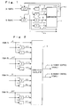
- a specific embodiment of the comparator 10 will be described with reference to FIG. 2 as a reference symbol A denotes an output signal of the third frame memory 3, a reference symbol B denotes an output signal of the fourth frame memory 4, a reference symbol AF denotes an output signal of the fifth frame memory 5 and a reference symbol BF denotes an output signal of the sixth frame memory 6 in FIG. 1.
- the comparator 10 is configured by 1-pixel delay portions 11, 13, 15 and 17 for delaying the output signals A, AF B and BF by one pixel, one line delay portions 12, 14, 16 and 18 for delaying the output signals A, AF B and BF by one line and a correlation calculator 19.
- the correlation calculator 19 six sorts of the signals with respect to the A route including the output signals A, one pixel delay signal AD of the signal A, one line delay signal AL of the signal A, one frame delay signal AF of the output signal A, one pixel delay signal AFD of the signal AF and one line delay signal AF of the signal AF are inputted. Further, in the correlation calculator 19, six sorts of the signals with respect to the B route including the output signal B, one pixel delay signal BD of the signal B, one line delay signal BL of the signal B, one frame delay signal BF of the output signal B, one pixel delay signal BFD of the signal BF and one line delay signal BFL of the signal BF are inputted.
- the correlation calculator 19 is configured by pixel value difference absolute value sum calculators (SAD) 21 to 35, a minimum value comparator 40, in which respective outputs of these pixel value difference absolute value sum calculators 21 to 35 are inputted, and a decoder 41 to output memory control signals 42 and 43 by decoding the output R of the minimum value comparator 40.
- SAD pixel value difference absolute value sum calculators
- minimum value comparator 40 in which respective outputs of these pixel value difference absolute value sum calculators 21 to 35 are inputted
- decoder 41 to output memory control signals 42 and 43 by decoding the output R of the minimum value comparator 40.
- the pixel value difference absolute value sum calculator 21 obtains a pixel value difference absolute value sum S0 by the following calculation.
- N represents the number of pixels in one screen.
- the pixel value difference absolute value sum calculators 21 to 35 obtain pixel value difference absolute value sums S1 to S14 from the combinations of the signals (A, AD, AL, AF, AFD, AFL) and the signals (B, BD, BL, BF, BFD, BFL). Then, the fifteen output signals S0 to S14 of these pixel value difference absolute value sum calculators 21 to 35 are inputted in the minimum value comparator 40.
- the minimum value comparator 40 obtains the minimum value from these output signals S0 to S14 and notifies the decoder 41 of one of a terminal numbers (indexes) 0 to 14 having the minimum value as its output R.
- the decoder 41 has a table as shown in FIG.
- a A memory control signal 42 or a B memory control signal 43 is outputted from the decoder 41, the delay amount of the first or second FIFO-type frame memory 1 or 2 (refer to FIG. 1) is controlled by these control signals 42 and 43.
- the delay amount of the first FIFO-type frame memory 1 or the second FIFO-type frame memory 2 is controlled. Therefore, the positional difference or the delay difference of the videos between the A route and the B route is gradually corrected so that the correlation becomes higher.
- the present positional difference or the delay difference i.e., the horizontal difference, the vertical difference and the time axis difference
- the horizontal difference means the pixel difference
- the vertical difference means the line difference
- the time axis difference means the frame difference, respectively.
- these outputs 44 and 45 may be used as an input image signal of an image failure detecting apparatus described in Japanese Patent Application NO. 11-156432 filled by the present applicant.
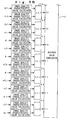
- the specific embodiment is characterized in that difference absolute value sum calculators (SAD) 51 to 65 are provided and further, image quality characteristic value calculators 51a, 51b to 65a and 65b are provided at a previous stage of the difference absolute value sum calculators (SAD) 51 to 65.
- SAD difference absolute value sum calculators
- image quality characteristic value calculators 51a, 51b to 65a and 65b are provided at a previous stage of the difference absolute value sum calculators (SAD) 51 to 65.
- Each of the image quality characteristic value calculators 51a, 51b to 65a and 65b calculates the image quality characteristic value in each block (for example, 16 pixels X 16 lines), which is formed by dividing the screens of the A route and the B route into blocks.
- the image quality characteristic value an average value of a pixel value in a block and a dispersion value of the pixel value in a block may be cited.
- the difference absolute value sum calculators (SAD) 51 to 65 calculate a sum of the difference absolute values of the image quality characteristic values in the A and B routes . In other words, one difference absolute value is obtained for each block, so that each of the difference absolute value sum calculators (SAD) 51 to 65 sums up the difference absolute values in a whole screen. As the difference absolute value is smaller, the correlation of the videos of the A and B routes is larger.
- a second embodiment according to the present invention will be explained with reference to FIG. 6.
- the embodiment is characterized in that a seventh frame memory 7 and an eighth frame memory 8 are further connected to the rear stages of the fifth frame memory 5 and the sixth frame memory 6, respectively, makes signals which are further delayed by one frame than the first embodiment to provide these signals to the comparator 10.
- the number of parts of a circuit is increased, however, it becomes possible to correct the positional difference of the videos of the A route and the B route at a higher speed.
- a third embodiment according to the present invention will be explained with reference to FIG. 7.
- the embodiment is characterized in that a third FIFO-type frame memory 70 and a fourth FIFO-type frame memory 71 are provided in a circuit in parallel with the first FIFO-type frame memory 1 and the second FIFO-type frame memory 2 and the positional difference of videos is corrected by these third and fourth FIFO-type frame memories 70 and 71 after the correcting amount of the positional difference of the videos by the first and second FIFO-type frame memories 1 and 2 is finally decided.
- the same reference numerals as those in FIG. 1 denote the same or the equivalent components as those in FIG. 1.
- a control signal storing portion 72 stores the A memory control signal 42 and the B memory control signal 43 while the positional difference of the videos has been corrected by using the first and second FIFO-type frame memories 1 and 2.
- a correction completion signal 73 namely, a signal such that both of the A memory control signals 42 and 43 are 0
- a switch 74 is closed and a A memory control signal 42a and a B memory control signal 42b, which have been stored in the control signal storing portion 72, are transmitted in gross to the third and the fourth FIFO-type frame memories 70 and 71.
- the comparator 69 is configured by a comparator 10 and a switch controlling unit 69a. Additionally, the comparator unit 10 has the same constitution of that shown in FIG. 2.
- the output R from the comparator 10 (the output R from the minimum value comparator 40) is inputted in the control signal storing portion 72 and the switch controlling unit 69a.
- the control signal storing portion 72 detects the final correcting amount of the positional difference of the videos by updating the data whenever the output R is inputted.
Landscapes
- Engineering & Computer Science (AREA)
- Multimedia (AREA)
- Signal Processing (AREA)
- Compression Or Coding Systems Of Tv Signals (AREA)
- Picture Signal Circuits (AREA)
- Testing, Inspecting, Measuring Of Stereoscopic Televisions And Televisions (AREA)
- Television Systems (AREA)
Applications Claiming Priority (2)
| Application Number | Priority Date | Filing Date | Title |
|---|---|---|---|
| JP2000332666A JP3739274B2 (ja) | 2000-10-31 | 2000-10-31 | 2系統映像の位置ずれ補正装置 |
| JP2000332666 | 2000-10-31 |
Publications (3)
| Publication Number | Publication Date |
|---|---|
| EP1202562A2 true EP1202562A2 (fr) | 2002-05-02 |
| EP1202562A3 EP1202562A3 (fr) | 2005-01-12 |
| EP1202562B1 EP1202562B1 (fr) | 2013-03-13 |
Family
ID=18808842
Family Applications (1)
| Application Number | Title | Priority Date | Filing Date |
|---|---|---|---|
| EP01125420A Expired - Lifetime EP1202562B1 (fr) | 2000-10-31 | 2001-10-31 | Dispositif de correction de la différence de retard entre deux signaux vidéo transmis sur des canaux distincts |
Country Status (3)
| Country | Link |
|---|---|
| US (1) | US6909468B2 (fr) |
| EP (1) | EP1202562B1 (fr) |
| JP (1) | JP3739274B2 (fr) |
Cited By (2)
| Publication number | Priority date | Publication date | Assignee | Title |
|---|---|---|---|---|
| EP1276260A3 (fr) * | 2001-06-18 | 2005-10-12 | Matsushita Electric Industrial Co., Ltd. | Dispositif de delai differentiel de signal, recepteur et système de communication utilisant ce dispositif |
| CN117294809A (zh) * | 2023-09-23 | 2023-12-26 | 北京流金岁月传媒科技股份有限公司 | 一种主备信号画面比对方法、系统、装置及介质 |
Families Citing this family (7)
| Publication number | Priority date | Publication date | Assignee | Title |
|---|---|---|---|---|
| KR100824711B1 (ko) * | 2003-08-22 | 2008-04-24 | 니뽄 덴신 덴와 가부시키가이샤 | 영상 정합 장치, 영상 정합 방법, 및 영상 정합 프로그램을기록한 기록매체 |
| US7738664B2 (en) | 2003-10-07 | 2010-06-15 | Kddi Corporation | Apparatus for fault detection for parallelly transmitted audio signals and apparatus for delay difference detection and adjustment for parallelly transmitted audio signals |
| JP4504714B2 (ja) * | 2004-03-26 | 2010-07-14 | リーダー電子株式会社 | 外部同期信号生成回路および位相差測定回路 |
| CN101052702B (zh) | 2004-07-16 | 2013-01-09 | 杜邦营养生物科学有限公司 | 脂肪分解酶及其在食品工业中的应用 |
| JP4783724B2 (ja) * | 2006-12-28 | 2011-09-28 | 日本放送協会 | 地上デジタル放送用ts切替器及び方法 |
| US8692937B2 (en) * | 2010-02-25 | 2014-04-08 | Silicon Image, Inc. | Video frame synchronization |
| US10674180B2 (en) | 2015-02-13 | 2020-06-02 | Netflix, Inc. | Techniques for identifying errors introduced during encoding |
Citations (1)
| Publication number | Priority date | Publication date | Assignee | Title |
|---|---|---|---|---|
| JPH11156432A (ja) | 1997-11-25 | 1999-06-15 | Kawasaki Steel Corp | スクイズ装置 |
Family Cites Families (14)
| Publication number | Priority date | Publication date | Assignee | Title |
|---|---|---|---|---|
| US241389A (en) * | 1881-05-10 | Railway-tie | ||
| CA1311063C (fr) * | 1988-12-16 | 1992-12-01 | Tokumichi Murakami | Processeur de signaux numeriques |
| JPH04207788A (ja) * | 1990-11-30 | 1992-07-29 | Sony Corp | 画像信号符号化装置及び方法 |
| US5241389A (en) | 1991-07-29 | 1993-08-31 | Intelligent Resources Integrated Systems, Inc. | Video display system providing for synchronization of multiple video data streams |
| US5446492A (en) * | 1993-01-19 | 1995-08-29 | Wolf; Stephen | Perception-based video quality measurement system |
| US5530483A (en) * | 1994-10-11 | 1996-06-25 | Pixel Instruments Corp. | Delay detector apparatus and method for plural image sequences |
| JP3025415B2 (ja) * | 1995-01-20 | 2000-03-27 | ケイディディ株式会社 | ディジタル圧縮・再生画像の画質評価装置 |
| US6330033B1 (en) * | 1995-12-07 | 2001-12-11 | James Carl Cooper | Pulse detector for ascertaining the processing delay of a signal |
| IL119504A (en) | 1996-10-28 | 2000-09-28 | Elop Electrooptics Ind Ltd | Audio-visual content verification method and system |
| JP3631868B2 (ja) * | 1996-12-20 | 2005-03-23 | 株式会社東芝 | 動きベクトル検出装置および方法 |
| US5894324A (en) * | 1997-12-03 | 1999-04-13 | Tektronix, Inc. | Video alignment using a selected partial picture |
| US6127950A (en) * | 1998-02-16 | 2000-10-03 | Matsushita Electric Industrial Co., Ltd. | Transmission circuit and reception circuit |
| JP3053607B2 (ja) * | 1998-04-08 | 2000-06-19 | 三菱電機株式会社 | データ照合方法およびその装置 |
| US6259477B1 (en) | 1998-06-23 | 2001-07-10 | Tektronix, Inc. | Joint spatial-temporal alignment of video sequences |
-
2000
- 2000-10-31 JP JP2000332666A patent/JP3739274B2/ja not_active Expired - Fee Related
-
2001
- 2001-10-30 US US09/984,585 patent/US6909468B2/en not_active Expired - Lifetime
- 2001-10-31 EP EP01125420A patent/EP1202562B1/fr not_active Expired - Lifetime
Patent Citations (1)
| Publication number | Priority date | Publication date | Assignee | Title |
|---|---|---|---|---|
| JPH11156432A (ja) | 1997-11-25 | 1999-06-15 | Kawasaki Steel Corp | スクイズ装置 |
Cited By (3)
| Publication number | Priority date | Publication date | Assignee | Title |
|---|---|---|---|---|
| EP1276260A3 (fr) * | 2001-06-18 | 2005-10-12 | Matsushita Electric Industrial Co., Ltd. | Dispositif de delai differentiel de signal, recepteur et système de communication utilisant ce dispositif |
| CN117294809A (zh) * | 2023-09-23 | 2023-12-26 | 北京流金岁月传媒科技股份有限公司 | 一种主备信号画面比对方法、系统、装置及介质 |
| CN117294809B (zh) * | 2023-09-23 | 2024-04-23 | 北京流金岁月传媒科技股份有限公司 | 一种主备信号画面比对方法、系统、装置及介质 |
Also Published As
| Publication number | Publication date |
|---|---|
| JP3739274B2 (ja) | 2006-01-25 |
| EP1202562B1 (fr) | 2013-03-13 |
| EP1202562A3 (fr) | 2005-01-12 |
| US20020071054A1 (en) | 2002-06-13 |
| JP2002142131A (ja) | 2002-05-17 |
| US6909468B2 (en) | 2005-06-21 |
Similar Documents
| Publication | Publication Date | Title |
|---|---|---|
| US8559527B2 (en) | Image display apparatus | |
| US6091460A (en) | Video signal encoding method and system | |
| US6340990B1 (en) | System for deinterlacing television signals from camera video or film | |
| US4562466A (en) | Digital data transmission/reception having adaptive error control | |
| EP0740471A2 (fr) | Système de codage et de transmission d'images | |
| US7738042B2 (en) | Noise reduction device for a video signal and noise reduction method for a video signal | |
| EP1202562A2 (fr) | Dispositif de correction de la différence de retard entre deux signaux vidéo transmis sur des canaux distincts | |
| US20040008275A1 (en) | Apparatus for and method of detecting whether incoming image signal is in film mode | |
| US6351545B1 (en) | Motion picture enhancing system | |
| CA2090382C (fr) | Methode et appareil de reception d'images animees | |
| US6772392B1 (en) | Image failure detection unit in redundant duplex transmission | |
| US7724979B2 (en) | Video preprocessing temporal and spatial filter | |
| EP1641270A1 (fr) | Dispositif et procede de detection de deformation des blocs et dispositif de traitement de signaux video | |
| US6611559B1 (en) | Apparatus and method of detecting motion vectors by calculating a correlation degree between each candidate block | |
| US8976186B2 (en) | Image processing apparatus and method thereof | |
| US8243161B2 (en) | Repetitive object detecting device and method | |
| EP0135255B1 (fr) | Equipement de codage/décodage intertrame pourvu d'un système pour détecter une erreur de transmission | |
| US20010026328A1 (en) | Encoding method and device | |
| AU2004200237B2 (en) | Image processing apparatus with frame-rate conversion and method thereof | |
| US6643326B1 (en) | Picture decoding apparatus modifying received temporal references | |
| KR19980051713A (ko) | 전송되는 비디오 신호의 에러 은폐 방법 및 장치 | |
| US6483550B1 (en) | Video signal level converting device and video signal analog-to-digital converter | |
| EP0528366B1 (fr) | Méthode et configuration de circuit pour la détection de mouvement dans une image de télévision | |
| EP0220946B1 (fr) | Détecteur à seuil numérique avec hystérèse | |
| JP2005117312A (ja) | 2系統音声信号間の遅延差検出および補正装置 |
Legal Events
| Date | Code | Title | Description |
|---|---|---|---|
| PUAI | Public reference made under article 153(3) epc to a published international application that has entered the european phase |
Free format text: ORIGINAL CODE: 0009012 |
|
| 17P | Request for examination filed |
Effective date: 20011031 |
|
| AK | Designated contracting states |
Kind code of ref document: A2 Designated state(s): AT BE CH CY DE DK ES FI FR GB GR IE IT LI LU MC NL PT SE TR |
|
| AX | Request for extension of the european patent |
Free format text: AL;LT;LV;MK;RO;SI |
|
| PUAL | Search report despatched |
Free format text: ORIGINAL CODE: 0009013 |
|
| AK | Designated contracting states |
Kind code of ref document: A3 Designated state(s): AT BE CH CY DE DK ES FI FR GB GR IE IT LI LU MC NL PT SE TR |
|
| AX | Request for extension of the european patent |
Extension state: AL LT LV MK RO SI |
|
| RIC1 | Information provided on ipc code assigned before grant |
Ipc: 7H 04N 5/04 A Ipc: 7H 04N 5/073 B |
|
| AKX | Designation fees paid |
Designated state(s): DE FR GB |
|
| 17Q | First examination report despatched |
Effective date: 20090316 |
|
| GRAP | Despatch of communication of intention to grant a patent |
Free format text: ORIGINAL CODE: EPIDOSNIGR1 |
|
| RIN1 | Information on inventor provided before grant (corrected) |
Inventor name: KAWADA, RYOICHI Inventor name: WADA, MASAHIRO Inventor name: MATSUMOTO, SHUICHI |
|
| GRAS | Grant fee paid |
Free format text: ORIGINAL CODE: EPIDOSNIGR3 |
|
| GRAA | (expected) grant |
Free format text: ORIGINAL CODE: 0009210 |
|
| RAP1 | Party data changed (applicant data changed or rights of an application transferred) |
Owner name: KDDI CORPORATION |
|
| AK | Designated contracting states |
Kind code of ref document: B1 Designated state(s): DE FR GB |
|
| REG | Reference to a national code |
Ref country code: GB Ref legal event code: FG4D |
|
| REG | Reference to a national code |
Ref country code: DE Ref legal event code: R096 Ref document number: 60147752 Country of ref document: DE Effective date: 20130508 |
|
| PLBE | No opposition filed within time limit |
Free format text: ORIGINAL CODE: 0009261 |
|
| STAA | Information on the status of an ep patent application or granted ep patent |
Free format text: STATUS: NO OPPOSITION FILED WITHIN TIME LIMIT |
|
| 26N | No opposition filed |
Effective date: 20131216 |
|
| REG | Reference to a national code |
Ref country code: DE Ref legal event code: R097 Ref document number: 60147752 Country of ref document: DE Effective date: 20131216 |
|
| REG | Reference to a national code |
Ref country code: FR Ref legal event code: ST Effective date: 20140630 |
|
| REG | Reference to a national code |
Ref country code: DE Ref legal event code: R119 Ref document number: 60147752 Country of ref document: DE Effective date: 20140501 |
|
| PG25 | Lapsed in a contracting state [announced via postgrant information from national office to epo] |
Ref country code: FR Free format text: LAPSE BECAUSE OF NON-PAYMENT OF DUE FEES Effective date: 20131031 Ref country code: DE Free format text: LAPSE BECAUSE OF NON-PAYMENT OF DUE FEES Effective date: 20140501 |
|
| PGFP | Annual fee paid to national office [announced via postgrant information from national office to epo] |
Ref country code: GB Payment date: 20171019 Year of fee payment: 17 |
|
| GBPC | Gb: european patent ceased through non-payment of renewal fee |
Effective date: 20181031 |
|
| PG25 | Lapsed in a contracting state [announced via postgrant information from national office to epo] |
Ref country code: GB Free format text: LAPSE BECAUSE OF NON-PAYMENT OF DUE FEES Effective date: 20181031 |