EP1202605A2 - Verfahren zum Konfigurieren einer Beschallungsanlage und konfigurierbare Beschallungsanlage - Google Patents
Verfahren zum Konfigurieren einer Beschallungsanlage und konfigurierbare Beschallungsanlage Download PDFInfo
- Publication number
- EP1202605A2 EP1202605A2 EP01122387A EP01122387A EP1202605A2 EP 1202605 A2 EP1202605 A2 EP 1202605A2 EP 01122387 A EP01122387 A EP 01122387A EP 01122387 A EP01122387 A EP 01122387A EP 1202605 A2 EP1202605 A2 EP 1202605A2
- Authority
- EP
- European Patent Office
- Prior art keywords
- data
- signal processing
- amplifier
- loudspeaker box
- digital signal
- Prior art date
- Legal status (The legal status is an assumption and is not a legal conclusion. Google has not performed a legal analysis and makes no representation as to the accuracy of the status listed.)
- Withdrawn
Links
Images


Classifications
-
- H—ELECTRICITY
- H04—ELECTRIC COMMUNICATION TECHNIQUE
- H04R—LOUDSPEAKERS, MICROPHONES, GRAMOPHONE PICK-UPS OR LIKE ACOUSTIC ELECTROMECHANICAL TRANSDUCERS; ELECTRIC HEARING AIDS; PUBLIC ADDRESS SYSTEMS
- H04R29/00—Monitoring arrangements; Testing arrangements
- H04R29/007—Monitoring arrangements; Testing arrangements for public address systems
-
- H—ELECTRICITY
- H04—ELECTRIC COMMUNICATION TECHNIQUE
- H04R—LOUDSPEAKERS, MICROPHONES, GRAMOPHONE PICK-UPS OR LIKE ACOUSTIC ELECTROMECHANICAL TRANSDUCERS; ELECTRIC HEARING AIDS; PUBLIC ADDRESS SYSTEMS
- H04R27/00—Public address systems
-
- H—ELECTRICITY
- H04—ELECTRIC COMMUNICATION TECHNIQUE
- H04R—LOUDSPEAKERS, MICROPHONES, GRAMOPHONE PICK-UPS OR LIKE ACOUSTIC ELECTROMECHANICAL TRANSDUCERS; ELECTRIC HEARING AIDS; PUBLIC ADDRESS SYSTEMS
- H04R3/00—Circuits for transducers
- H04R3/007—Protection circuits for transducers
Definitions
- the invention relates to a method for configuring a Public address system with at least one loudspeaker and an audio signal supplying the speaker box, an amplifier comprising DSP in the audio signal path. Further The invention relates to a configurable public address system as well as a loudspeaker and an amplifier, which in of such a configurable public address system are.
- the constantly changing structure of the sound system has Consequence that optimal acoustic results are not always achieved become.
- the invention has for its object a method for Configure a PA system to specify which one Optimization of the system with any combination of amplifiers and loudspeaker box. Furthermore, a corresponding Public address system, a loudspeaker box and a correspondingly configurable amplifiers can be created.
- data is stored in the loudspeaker box, which a certain, desired signal processing in Affect amplifiers.
- the loudspeaker gives these data the signal processing in the amplifier before that leads to the best possible sound result. So the data can as a "regulation for optimized amplifier operation" be understood.
- the data are in one both amplifier hardware / software non-specific as well in a loudspeaker-unspecific data format.
- the data in a by universal Rules which are independent of the specific one used Amplifiers and the specific loudspeaker used predetermined form are stored in the speaker box and be transmitted.
- data format the whole of these rules or conventions.
- the data is transferred from the speaker box to the amplifier transferred and interpreted there.
- the interpretation data contain the required information about the digital signal processing section used, especially DSP, and therefore enable the Calculation or generation of the settings for the digital Signal processing section required specific Parameter data.
- the interpretation data specify which signal processing steps from the specific Case DSP implemented in the amplifier are executable, for which signal processing steps other components in the amplifier and on the other hand, which signal processing steps of the specific amplifier hardware / software not be supported.
- the interpretation data So put the exact knowledge of what is used in the amplifier DSP ahead and contain the hardware-specific Information with which the transmitted from the loudspeaker box Data in DSP-specific setting or parameter data can be implemented.
- the invention between the speakers data and the amplifier hardware / software a new level of translation or interpretation introduced, which allows loudspeakers and amplifiers in a self-configuring public address system Operate and mix across types and generations to be able to.
- the presentation of the data in the loudspeaker box should be next to the required generality as low as possible Computational effort when interpreting the data and Support the shortest possible data transfer times. This requires optimization of the form of presentation of the data (i.e. the data format) especially with regard to avoidance of redundancy in the records.
- At least some of the data records are preferably each one assigned functional element known in amplifier technology, the respective functional element by means of a functional element identification data field unique in the data set is identifiable.
- the functional element identification data field facilitates the interpretation of the received Data.
- the term functional element is too broad understand and can be both a hardware component (either hybrid or integrated in the DSP) as well as a software module in the denote digital signal processing section of the amplifier.
- a first data record of a filter sequence For example, a first data record of a filter sequence, a second record a peak limiter (so-called peak limiter) to avoid a short-term Speaker overload, a third record of a diaphragm deflection limiter to limit the membrane deflection, a fourth record of a continuous power limiter (sometimes also known as a thermal limiter) to limit the Continuous output power of the amplifier, a fifth record a relative time lag of the audio signal other outputs of the amplifier and a sixth record the total gain and phase of that from the amplifier output audio signal must be assigned (the numbering does not imply any particular sequence of records in the data format).
- peak limiter peak limiter
- a diaphragm deflection limiter to limit the membrane deflection
- a fourth record of a continuous power limiter sometimes also known as a thermal limiter
- the first record (which is assigned to a filter sequence is) can furthermore have a filter identification data field, which is used to identify different filter types serves.
- a filter identification data field which is used to identify different filter types serves.
- a data record has a data record identification data field.
- This data field is, for example, with a continuous Number assignable and enables the Differentiation also of such data sets, the identical functional elements assigned (i.e. identical functional element identification data fields exhibit). This will achieved that several versions for one and the same component of a data record can be created.
- the provision of a record identification data field in the record takes into account the fact that it is for a speaker possibly not just a valid setting of the amplifier, especially the DSP. Because for different Operating modes and installation options etc. of the loudspeaker different optimized parameter data result for the amplifier. That is why the data format offers in the way indicated the possibility of different Specify versions of records which (after data interpretation) to different settings of the amplifier or DSP. The setting options can then selected on the amplifier or on the respective amplifier channel become.
- the interpretation data is also required for the data conversion, which are held in the amplifier.
- This Data relate exclusively to information relating to the Amplifiers used hardware and possibly software (Firmware) and are therefore also before downloading the data from the loudspeaker box is available in the amplifier.
- the interpretation data are independent of the straight one connected loudspeaker, i.e. it is not necessary, the interpretation data at the launch of update new speakers.
- An update of the However, interpretation data can be used when converting the Amplifier (e.g. replacement of the DSP or a new programming of the DSP) become necessary. It can therefore be beneficial be the interpretation data in a programmable Keep memory, which is written via an interface can be.
- the interpretation data can be freely selected (i.e. device-specific) data format held in the amplifier become.
- the interpretation data preferably contain data which are assigned to the channel structure of the amplifier, for example Information about the number and structure of each Channels; Data on the sampling frequency used in the DSP; an indication of the gain factor of a power amplifier stage the amplifier; an indication of the Short-term output voltage, e.g. as the sine mean, one Power amplifier stage of the amplifier; and information about the internal delay times of an analog-to-digital converter or a digital-to-analog converter in the audio signal path of the amplifier in front of and behind the DSP.
- An advantageous measure of the method according to the invention is that before converting the data obtained into Parameter data for the digital signal processing section it is checked whether this is the requested signal processing provides at all.
- a simple form of one Verification is, for example, checking whether sufficient amplifier channels available in the amplifier and whether enough output power from the amplifier is available stands.
- it can be checked, for example, whether the digital signal processing section, in particular DSP or the DSP software (firmware), requested signal processing steps supported. If the review leads to the result that for the digital signal processing section a requested signal processing cannot be carried out the user can do this by issuing a Warning notice will be communicated.
- a warning can be issued in an advantageous manner if, when implementing the data, the occurrence of a Error is detected.
- the amplifier works without corresponding data from the loudspeaker in a preset standard operating mode. If a connected speaker data transmitted, which is only a part of the digital signal processing section, especially DSP Signal processing functions are preferred provided that the other signal processing functions Define according to the default.
- this is a data storage includes in which the desired signal processing data in an amplifier in a predetermined, data format independent of the type of the loudspeaker are. These can then in the manner already explained by an amplifier that has the data interpretation functionality described above exhibits, evaluated and used.
- An essential aspect of the amplifier according to the invention consists in the fact that it comprises an interpretation unit, which is based on the interpretation data from the Loudspeaker received data calculated the parameter data to configure the digital signal processing section, especially suitable and necessary DSP.
- the amplifier 1 shows a schematic representation of an amplifier 1, which is designed as a power amplifier.
- the amplifier 1 has an audio signal processing circuit which is shown in is designated in its entirety with 2.
- the audio signal processing circuit 2 includes a DSP 2.2, usually one the DSP 2.2 upstream analog-to-digital converter 2.1 and a digital-to-analog converter downstream of the DSP 2.2 2.3 and a power amplifier stage 2.4.
- the analog-digital and digital-to-analog converter 2.1, 2.3 are optional because the amplifier 1 is also supplied with a digital input signal can also be a reinforcement in digital Signal range can take place. Further amplifier components can also be used in the audio signal processing circuit 2 be included.
- the amplifier 1 further comprises a configuration circuit 3.
- the configuration circuit 3 is a Data storage 4 assigned.
- the configuration circuit 3 is available via a data transmission medium (e.g. data bus) 5 the audio signal processing circuit 2 in data connection and is capable of 6 data via a data transmission means read out from the data memory 4.
- a storage medium 9 is assigned to a loudspeaker box 8.
- the loudspeaker box 8 is connected via a cable connection 10 connected to the amplifier 1, the cable connection 10 from a speaker cable 11 and a data transmission link 12 exists. It can be seen from the direction of the arrow that corresponding audio signals for operating the loudspeaker box 8 are transmitted from amplifier 1 to loudspeaker box 8.
- the Data transmission path 12 is provided with double arrows, which indicates that bidirectional data exchange between the configuration circuit 3 and the storage medium 9 possible is.
- speaker wire 11 can also be used for data transmission. In this case there is no separate data transmission link 12.
- FIG. 2 shows a further example of a public address system, in which the same or functionally identical parts as in 1 are designated by the same reference numerals.
- the Audio signal processing circuit 2 ' is shown in FIG Example of two-channel design (analog-digital converter 2.1 ', DSP 2.2', digital-to-analog converter 2.3 ', power amplifier stage 2.4 '), with an individual in each channel Signal processing is possible.
- the DSP 2.2 ' for receive different parameter values for each channel and as Can use setting values and that the audio signal above it can be amplified differently in each channel.
- the audio signal processing circuit 2 ' can also be essential have more than two channels.
- the amplifier 1 is switched on in step S1.
- the amplifier experiences or ascertains its channels 1, in step S2 whether and at which output connections loudspeaker boxes 8, 8 'are connected.
- step S3 a transfer takes place in the storage media 9, 9 'of the speakers 8, 8' stored data in the Configuration circuit 3 of the amplifier 1.
- the configuration circuit 3 a communication request to the connected loudspeaker box 8, 8 'is sent, whereupon those in the storage media 9, 9 'stored data in one of the configuration circuit 1 allocated memory area (not shown) be transmitted. Data can be retrieved at the same time or individually for each speaker box 8, 8 '.
- the data interpretation which is more closely based on FIGS. 4 and 5 is based on additional information about the hardware and / or software structure in the amplifier, which is available for configuration circuit 3.
- This additional Information is in the form of so-called interpretation data stored in the data memory 4. Access to this data is done as required in the course of data interpretation. For example, it is conceivable that a loudspeaker box 8, 8 'a certain setting of a component (e.g. a specific digital filter). In this case first by calling up the corresponding interpretation data determined whether this filter in the DSP 2.2, 2.2 ' or maybe as a separate component elsewhere in the Signal path of the audio signal processing circuit 2, 2 'or is present at all.
- a component e.g. a specific digital filter
- the interpretation data stored in the data memory 4 concern only information about hardware and / or Software in the amplifier, i.e. via the DSP 2.2, 2.2 'if necessary the other in the audio signal processing circuit 2, 2 'contained functional elements. Because this information is independent of different speaker types, it remains valid for future generations of loudspeakers. It is therefore always possible to calculate parameter values on the basis of the respective loudspeaker boxes 8, 8 ' transferred data taking into account the interpretation data be performed.
- step S5 the calculated parameter values are over the Data transmission means 5 of the audio signal processing circuit 2, 2 'fed. This becomes corresponding in step S6 of the received parameter values configured. If there is of several channels is the calculation of the parameter values performed for each of the channels and a corresponding one Setting of the multi-channel DSP 2.2 'made. As a result it is achieved that all connected speakers 8, 8 'show an optimized sound behavior.
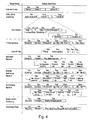
- Fig. 4 shows a preferred data format for that in the speaker storage medium 9, 9 'stored data.
- the data format includes a variety of data sets, which by use different data types are structured. It e.g. the data types CHARACTER (characters, letters), abbreviated with “Char”, INTEGER (integers), in Fig. 4 the For the sake of simplicity abbreviated to "byte”, REAL (floating point number), abbreviated here by "float”, as the format of the individual Data fields used.
- a first record contains the name of the speaker and includes 16 data fields of the type Char.
- a second data set creates the possibility of different Create variants of data records.
- This record defines the signal processing in its structural structure.
- the data record includes the data fields (the assigned data types are in brackets): Number of variants M (byte) / ... and a number of M data field sequences variant 1, ... variant M, each a more detailed description of each Enable variants.
- the structure of each of these data field sequences is: Character 1 (Char) /.../ Character 16 (Char) / number of elements N (byte) / element number 1 (byte) /.../ element number N (Byte).
- This Data record contains the data fields (data types): Element ID (Byte) / element number (byte) / number of filters N (byte) / total scaling (Float) / ... and a number of N data field sequences IIR filter 1 to IIR filter N, each with five data fields of the data types contain byte, float, float, float, float, and the structure of which is explained in more detail below.
- N corresponds to the number of those contained in the filter arrangement Filter.
- the record concerns the peak limiter, by means of which an override of the output stage or a Overloading the speaker for short-term Excellence is avoided.
- the record contains the Data fields (data types): Element ID (byte) / element number (Byte) / maximum peak voltage (float) / compression ratio (Float) / response time (Float) / hold time (Float) / ramp-down time (Float) / averaging time constant (Float).
- Another data set relates to a membrane deflection limiter and includes the data fields (data types): Element ID (Byte) / element number (byte) / number of filters N (byte) / total scaling (Float) / ... then the already mentioned N Data field sequences IIR filter 1 to IIR filter N, ... on it then: maximum peak tension (float) / compression ratio (Float) / Response time (Float) / Hold time (Float) / Deceleration time (float) / averaging time constant (float).
- data types data types: Element ID (Byte) / element number (byte) / number of filters N (byte) / total scaling (Float) / ... then the already mentioned N Data field sequences IIR filter 1 to IIR filter N, ... on it then: maximum peak tension (float) / compression ratio (Float) / Response time (Float) / Hold time (Float) / Deceleration time (float) / averaging time constant (float).
- Another data set contains data relating to a continuous power limiter and includes the data fields (data types): Element ID (byte) / element number (byte) / number of filters N (Byte) / total scaling (float) / ... then the N Data field sequences IIR filter 1 to IIR filter N, ... on it then: maximum continuous output (float) / compression ratio (Float) / response time (Float) / hold time (Float) / ramp-down time (Float).
- Another data record includes the data fields (data types): Element ID (byte) / element number (byte) / relative delay time (Float), and relates to one in amplifier 1 relative to a reference point, for example the delay in one Adjacent channel, delay in the signal occurring.
- data types data types: Element ID (byte) / element number (byte) / relative delay time (Float), and relates to one in amplifier 1 relative to a reference point, for example the delay in one Adjacent channel, delay in the signal occurring.
- Another data set concerns the gain and the phase position of the audio signal at the output of amplifier 1 and contains the data fields (data types): Element ID (byte) / element number (Byte) / total gain including phase, the latter indicated by the sign (float).
- the records contain for description of the individual signal processing or functional elements in the amplifier 1, the identification field labeled Element ID.
- Table 1 is exemplary an association between the values for the Element data field ID and the currently used functional elements (Signal processing elements or signal processing functions) listed in amplifier 1. It can be seen that the table by adding additional functional elements lets expand.
- a functional element can generally be implemented in the form of hardware or software as well as a DSP-internal or DSP-external component in the audio signal processing circuit 2, 2 '.
- Element ID ⁇ -> functional element Element ID Description (signal processing element or function) 0 --- Reserved --- 1 IIR-Biquad filter sequence with variable number of filters. For possible filters, see filter type table 2.
- Peak value limiter To avoid loudspeaker overload due to signal peaks that are too high or peak power that is too high 3
- Membrane deflection limiter To limit the membrane deflection of the loudspeaker 4
- Continuous power / RMS value limiter To avoid loudspeaker damage (usually thermal overload) due to excessive output continuous power 5
- Relative time delay of the output signal for, for example, runtime adjustment of the different LS components in active LS systems 6
- the various filters of the filter arrangement for equalizing the loudspeaker transmission function are also provided with an identification field, which is designated by the term "filter type".
- filter type an identification field
- the following table 2 shows a possible assignment of the field variable filter type to a description of the corresponding filter type using characteristic data.
- the identification fields for the signal processing elements and for the filter types must before the technical realization the public address system according to the invention by convention (for example according to tables 1 and 2) and should then no longer be used for compatibility reasons be changed. By using the identification fields becomes the interpretation of that from the speakers 8, 8 'data obtained considerably simplified.
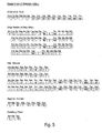
- Fig. 5 shows an example of a file for description of desired signal processing functions for a certain speaker cabinet.
- the structure of this file follows this data format explained in FIG. 4.
- the element numbers are in each of the following records in the entered the second data field and, as already mentioned, a sequential numbering of those data records represents a signal processing element or a signal processing function in the audio signal path.
- The are just those records whose first data field is a Identification field ("Element ID"), i.e. in which in Fig. 4 example shown all data records with the exception the record for the speaker name and the record for the variant definition.
- the four variants differ according to the variant definition by alternatively using the data records with the Element numbers 1 or 2 or 3 or 4 included, whereas the records with item numbers 5 and 6 in all Variants are included.
- the records with the element numbers 1 to 4 describe four different filter sequence versions.
- the first two filter sequence versions (records with element numbers 1 and 2) only contain a filter. In both cases it is the same Filter (filter type 4), the only difference in the Filter setting values for the frequency response fg (50 or 150) find is.
- the specified identification fields, variable and field types as well as the structure of the individual data records and elements can be defined and structured in many other ways become. It is crucial that through the selected data format on the one hand a description as comprehensive as possible all possible signal processing functions in one Amplifier is supported, and that on the other hand short transmission times and a simple one with little computation feasible interpretation of the in this format by the Data delivered to loudspeakers is possible. Furthermore the file format should be like the one shown here Example, be "open", so that future developments in the amplifier area through a "downward compatible" Format expansion can be taken into account.
- the interpretation data held in the data memory 4 of the amplifier 1 contain specific technical information or Numerical values regarding the structure or the specifications the amplifier hardware including firmware, which are necessary are from the data received from the speakers to calculate an "executable" parameter set. In contrast you need for the data supplied by the loudspeaker box not according to a special, generally applicable format convention be structured.
Landscapes
- Physics & Mathematics (AREA)
- Engineering & Computer Science (AREA)
- Acoustics & Sound (AREA)
- Signal Processing (AREA)
- Health & Medical Sciences (AREA)
- General Health & Medical Sciences (AREA)
- Otolaryngology (AREA)
- Circuit For Audible Band Transducer (AREA)
Abstract
Description
- Fig. 1
- ein Blockschaltbild einer erfindungsgemäßen Beschallungsanlage;
- Fig. 2
- ein Blockschaltbild einer weiteren erfindungsgemäßen Beschallungsanlage;
- Fig. 3
- ein Ablaufdiagramm zur Erläuterung des erfindungsgemäßen Verfahrens;
- Fig. 4
- eine Darstellung zur Erläuterung eines Datenformats der in dem Lautsprecher gehaltenen Daten; und
- Fig. 5
- ein Beispiel für eine Datei zur Beschreibung einer Signalbearbeitung im Verstärker, der das in Fig. 4 dargestellte Datenformat zugrunde liegt.
| (Element ID <-> Funktionselement) | |
| Element ID | Beschreibung (Signalverarbeitungselement bzw. -funktion) |
| 0 | --- Reserviert --- |
| 1 | IIR-Biquad Filtersequenz mit var. Filteranzahl. Mögliche Filter siehe Filtertyp-Tabelle 2. |
| 2 | Spitzenwert-Begrenzer: Zur Vermeidung von Lautsprecher-Überlastung durch zu hohe Signalspitzen bzw. zu hohe Spitzenleistung |
| 3 | Membran-Auslenkungs-Begrenzer: Zur Begrenzung der Membranauslenkung des Lautsprechers |
| 4 | Dauerleistungs-/Effektivwert-Begrenzer: Zur Vermeidung von Lautsprecher-Beschädigung (in der Regel thermische Überlastung) durch zu hohe Ausgangs-Dauerleistung |
| 5 | Relative zeitliche Verzögerungs des Ausgangssignals für z.B. Laufzeitanpassung der unterschiedlichen LS-Komponenten in Aktiv-LS-Systemen |
| 6 | Verstärkung und Phase der gesamten Verstärker- und Signalverarbeitungseinheit |
| (Filter-ID <-> Filtertyp) | |
| Filtertyp | Beschreibung |
| 0 | --- Reserviert --- |
| 1 | Tiefpaß 1. Ord. Parameter: Grenzfrequenz (fg) |
| 2 | Tiefpaß 2. Ord. (TP2) Parameter: Grenzfrequenz (fg), Güte (Q) |
| 3 | Hochpaß 1. Ord. Parameter: Grenzfrequenz (fg) |
| 4 | Hochpaß 2. Ord. Parameter: Grenzfrequenz (fg), Güte (Q) |
| 5 | Allpaß 1. Ord. (AP1) Parameter: Grenzfrequenz (fg) |
| 6 | Allpaß 2. Ord. Parameter: Grenzfrequenz (fg), Güte (Q) |
| 7 | Bandpaß 2. Ord. Parameter: Grenzfrequenz (fg), Güte (Q) |
| 8 | Präsenz-/Absenz-Filt. Parameter: Grenzfrequenz (fg), Güte (Q), Ver-bzw. EQ Filter 2. Ord. Stärkung (v) |
| 9 | Tiefenbewertungsfilter 1. Ord. Parameter: Grenzfrequenz (fg), Verstär-(Low Shelving Filter 1. Ord.) kung (v) |
| 10 | Tiefenbewertungsfilter 2. Ord. Parameter: Grenzfrequenz (fg), Güte (Q), (Low Shelving Filter 2. Ord.) Verstärkung (v) |
| 11 | Höhenbewertungsfilter 1. Ord. Parameter: Grenzfrequenz (fg), Verstär-(High Shelving Filter 1. Ord.) kung (v) |
| 12 | Höhenbewertungsfilter 2. Ord. Parameter: Grenzfrequenz (fg), Güte (Q), (High Shelving Filter 2. Ord.) Verstärkung (v) |
| 13 | Subtraktivfilter Parameter: Grenzfrequenz (fgAp,fgTp), (Allpaß 1. Ord. ± Tiefpaß 2. Ord.) Güte (Q), Verstärkung (v) |
| 14 | Kerbfilter 2. Ord. Parameter: Mittenfrequenz (fm), Güte (Q) |
- daß jede der vier Varianten drei Datensätze umfaßt, und
- daß die erste Variante durch die Elementnummern 1, 5, 6, die zweite Variante durch die Elementnummern 2, 5, 6, die dritte Variante durch die Elementnummern 3, 5, 6 und die vierte Variante durch die Elementnummern 4, 5, 6 definiert sind.
- Daten, die die Anzahl der Kanäle im Verstärker angeben;
- Daten, die die im DSP 2.2, 2.2' verwendete Abtastfrequenz angeben (diese kann gegebenenfalls von der Abtastfrequenz des Analog-Digital-Umsetzers 2.1, 2.1' abweichen);
- Daten, die die Grundverstärkung des Verstärkers 1 angeben;
- Daten, die die kurzzeitige maximale Ausgangsspannung (z.B. als Sinus RMS-Wert) des Verstärkers 1 angeben; und
- Daten, die die Zeitverzögerungen des Analog-Digital-Umsetzers 2.1, 2.1', des Digital-Analog-Umsetzers 2.3, 2.3' und des DSP 2.2, 2.2' angeben.
Claims (18)
- Verfahren zum Konfigurieren einer Beschallungsanlage mit mindestens einer Lautsprecherbox (8, 8') und einem die Lautsprecherbox (8, 8') mit einem Audiosignal versorgenden, einen digitalen Signalverarbeitungsabschnitt, insbesondere DSP (2.2, 2.2'), im Audiosignalpfad umfassenden Verstärker (1), wobei in der Lautsprecherbox (8, 8') Daten gespeichert sind, welche zu dem Verstärker (1) übertragen werden und anhand welcher eine an schalltechnische und/oder elektrische Charakteristiken oder Umgebungsbedingungen der Lautsprecherbox (8, 8') angepaßte Signalverarbeitung in dem digitalen Signalverarbeitungsabschnitt des Verstärkers (1) eingestellt wird, wobeidie Daten eine gewünschte Signalbearbeitung in dem digitalen Signalverarbeitungsabschnitt betreffen und in einem sowohl für den digitalen Signalverarbeitungsabschnitt als auch für die Lautsprecherbox (8, 8') unspezifischen Datenformat strukturiert sind,die Daten oder ein Teil derselben in einem im Verstärker (1) erfolgenden Interpretationsschritt (S4) in für den digitalen Signalverarbeitungsabschnitt spezifische, zur Konfiguration desselben geeignete Parameterdaten umgesetzt werden, undfür die Dateninterpretation im Verstärker (1) gehaltene Interpretationsdaten herangezogen werden, welche Informationen über die Beschaffenheit des verwendeten digitalen Signalverarbeitungsabschnitts zum Inhalt haben.
- Verfahren nach Anspruch 1,
dadurch gekennzeichnet, daß die in der Lautsprecherbox (8, 8') gespeicherten Daten in mehrere Datensätze jeweils eines vorgegebenen inhaltlichen Zusammenhangs eingeteilt sind. - Verfahren nach einem der vorhergehenden Ansprüche,
dadurch gekennzeichnet, daß zumindest einige der Datensätze jeweils einem in der Verstärkertechnik bekannten Funktionselement zugeordnet sind, wobei das jeweilige Funktionselement durch ein Funktionselement-Identifizierungs-Datenfeld im entsprechenden Datensatz eindeutig identifizierbar ist. - Verfahren nach Anspruch 3,
dadurch gekennzeichnet, daß ein erster Datensatz einer Filtersequenz zugeordnet ist. - Verfahren nach Anspruch 4,
dadurch gekennzeichnet, daß der erste Datensatz ein Filter-Identifizierungs-Datenfeld aufweist, welches zur Identifikation unterschiedlicher Filtertypen dient. - Verfahren nach Anspruch 3 bis 5,
dadurch gekennzeichnet, daß ein zweiter Datensatz einem Spitzenwert-Begrenzer zur Vermeidung einer Überlastung der Lautsprecherbox (8, 8') durch zu hohe Signalspitzen zugeordnet ist. - Verfahren nach Anspruch 3 bis 6,
dadurch gekennzeichnet, daß ein dritter Datensatz einem Membran-Auslenkungs-Begrenzer zur Begrenzung der Membranauslenkung zugeordnet ist. - Verfahren nach Anspruch 3 bis 7,
dadurch gekennzeichnet, daß ein vierter Datensatz einem Dauerleistungs-Begrenzer zur Begrenzung der Dauer-Ausgangsleistung zugeordnet ist. - Verfahren nach Anspruch 3 bis 8,
dadurch gekennzeichnet, daß ein fünfter Datensatz einer relativen zeitlichen Verzögerung des Audiosignals bezüglich anderer Ausgänge des Verstärkers (1) zugeordnet ist. - Verfahren nach Anspruch 3 bis 9,
dadurch gekennzeichnet, daß ein sechster Datensatz der Verstärkung und der Phase des von dem Verstärker ausgegebenen Audiosignals zugeordnet ist. - Verfahren nach Anspruch 3 bis 10,
dadurch gekennzeichnet, daß ein Datensatz ein Datensatz-Identifizierungs-Datenfeld aufweist, anhand welchem mehrere Versionen des Datensatzes unterscheidbar sind. - Verfahren nach einem der vorhergehenden Ansprüche,
dadurch gekennzeichnet,daß für Funktionselemente des digitalen Signalverarbeitungsabschnitts, insbesondere DSP (2.2, 2.2'), voreingestellte Parameterdaten im Verstärker (1) abgespeichert sind, unddaß die voreingestellten Parameterdaten zur Einstellung des zugehörigen Funktionselements herangezogen werden, wenn diesbezüglich keine Daten von der Lautsprecherbox (8, 8') übertragen werden. - Verfahren nach einem der vorhergehenden Ansprüchen,
dadurch gekennzeichnet, daß vor dem Umsetzen der erhaltenen Daten in Parameterdaten für den digitalen Signalverarbeitungsabschnitt, insbesondere DSP (2.2, 2.2'), überprüft wird, ob der digitale Signalverarbeitungsabschnitt die angeforderte Signalbearbeitung überhaupt zur Verfügung stellt. - Verfahren nach Anspruch 13,
dadurch gekennzeichnet, daß ein Warnhinweis ausgegeben wird, wenn die Überprüfung zu dem Ergebnis führt, daß für den digitalen Signalverarbeitungsabschnitt, insbesondere DSP (2.2, 2.2'), eine angeforderte Signalbearbeitung nicht ausführbar ist. - Verfahren nach einem der vorhergehenden Ansprüche,
dadurch gekennzeichnet, daß ein Warnhinweis ausgegeben wird, wenn bei der Interpretation der Daten das Auftreten eines Fehlers festgestellt wird. - Beschallungsanlage mit mindestens einer Lautsprecherbox (8, 8') und einem die Lautsprecherbox (8, 8') mit einem Audiosignal versorgenden, einen digitalen Signalverarbeitungsabschnitt, insbesondere DSP (2.2, 2.2'), im Audiosignalpfad umfassenden Verstärker (1), wobeidie Lautsprecherbox (8, 8') einen Datenspeicher (9, 9') umfaßt, in welchem Daten abgelegt sind, welche eine gewünschte Signalbearbeitung im Verstärker (1) betreffen und in einem sowohl für den digitalen Signalverarbeitungsabschnitt als auch für die Lautsprecherbox (8, 8') unspezifischen Datenformat strukturiert sind, undder Verstärker (1) einen Datenspeicher (4) zur Speicherung von Interpretationsdaten aufweist, welche Informationen über die Beschaffenheit des verwendeten digitalen Signalverarbeitungsabschnitts im Verstärker (1) zum Inhalt haben, undeine Interpretationseinheit umfaßt, die mittels der Interpretationsdaten aus den von der Lautsprecherbox (8, 8') erhaltenen Daten Parameterdaten berechnet, die zur Konfiguration des digitalen Signalverarbeitungsabschnitts geeignet sind.
- Lautsprecherbox
gekennzeichnet durch
einen Datenspeicher (9, 9'), in welchem in einem vorgegebenen, vom Typ der Lautsprecherbox (8, 8') unabhängigen Datenformat Daten abgelegt sind, welche eine bestimmte, gewünschte Signalbearbeitung in beliebigen digitalen Signalverarbeitungsabschnitten von Verstärkern (1) betreffen. - Konfigurierbarer Verstärker, der einen digitalen Signalverarbeitungsabschnitt im Audiosignalpfad aufweist und zur Ausgabe eines Audiosignals mit einer Lautsprecherbox verbindbar ist, der ferner eine Konfigurationsschaltung (3) aufweist,der Daten von der Lautsprecherbox (8, 8') zuleitbar sind, welche eine gewünschte Signalbearbeitung im Verstärker betreffen,die einen Datenspeicher (4) zur Speicherung von Interpretationsdaten aufweist, welche Informationen über den verwendeten digitalen Signalverarbeitungsabschnitt im Verstärker (1) betreffen, unddie eine Interpretationseinheit umfaßt, die mittels der Interpretationsdaten aus den von der Lautsprecherbox (8, 8') erhaltenen Daten unter Voraussetzung eines vorgegebenen, vom Typ des Lautsprechers unabhängigen Datenformats dieser Daten für den digitalen Signalverarbeitungsabschnitt spezifische, zur Konfiguration desselben geeignete Parameterdaten berechnet.
Applications Claiming Priority (2)
| Application Number | Priority Date | Filing Date | Title |
|---|---|---|---|
| DE10052896A DE10052896B4 (de) | 2000-10-25 | 2000-10-25 | Verfahren zum Konfigurieren einer Beschallungsanlage und konfigurierbare Beschallungsanlage |
| DE10052896 | 2000-10-25 |
Publications (2)
| Publication Number | Publication Date |
|---|---|
| EP1202605A2 true EP1202605A2 (de) | 2002-05-02 |
| EP1202605A3 EP1202605A3 (de) | 2005-07-20 |
Family
ID=7661023
Family Applications (1)
| Application Number | Title | Priority Date | Filing Date |
|---|---|---|---|
| EP01122387A Withdrawn EP1202605A3 (de) | 2000-10-25 | 2001-09-19 | Verfahren zum Konfigurieren einer Beschallungsanlage und konfigurierbare Beschallungsanlage |
Country Status (3)
| Country | Link |
|---|---|
| US (1) | US20020071572A1 (de) |
| EP (1) | EP1202605A3 (de) |
| DE (1) | DE10052896B4 (de) |
Families Citing this family (7)
| Publication number | Priority date | Publication date | Assignee | Title |
|---|---|---|---|---|
| JP2004023549A (ja) * | 2002-06-18 | 2004-01-22 | Denon Ltd | マルチチャンネル再生装置及びマルチチャンネル再生用スピーカ装置 |
| WO2004112425A1 (en) * | 2003-06-10 | 2004-12-23 | Harman International Industries, Incorporated | Audio amplifier with local interface system |
| AU2005318872B2 (en) * | 2004-12-26 | 2010-12-09 | Biamp Systems, LLC | An improved paging system |
| US7912234B1 (en) * | 2005-02-15 | 2011-03-22 | Graber Curtis E | Acoustic projector for propagating a low dispersion sound field |
| DE102006039162A1 (de) | 2006-08-21 | 2008-02-28 | Lear Corp., Southfield | Schutzverfahren für Lautsprechersysteme |
| NL2001646C2 (nl) * | 2008-06-03 | 2009-12-04 | Exsilent Res Bv | Geluidsweergavesysteem, drager, werkwijze voor het genereren van een correctieprofiel en werkwijze voor het generen van geluid. |
| DE102023213041A1 (de) * | 2023-12-20 | 2025-06-26 | Robert Bosch Gesellschaft mit beschränkter Haftung | Verfahren zur Konfiguration eines Audiogerätes einer Beschallungsanlage, Audiogerät, tragbares Bediengerät, Computerprogramm und maschinenlesbares Speichermedium |
Family Cites Families (5)
| Publication number | Priority date | Publication date | Assignee | Title |
|---|---|---|---|---|
| DE69228664T2 (de) * | 1991-11-11 | 1999-09-30 | Koninklijke Philips Electronics N.V., Eindhoven | System zur Anlagensteuerung mit einem gemeinsamen Kommunikationskanal |
| US5881103A (en) * | 1995-08-03 | 1999-03-09 | Motorola, Inc. | Electronic device with equalized audio accessory and method for same |
| DE19651308C2 (de) * | 1996-12-10 | 1998-10-22 | Becker Gmbh | Audio-Soundsystem für ein Kraftfahrzeug |
| DE19726176C1 (de) * | 1997-06-20 | 1999-01-21 | D & B Audiotechnik Ag | Verfahren und Vorrichtung zum Betreiben einer Beschallungsanlage |
| US6859538B1 (en) * | 1999-03-17 | 2005-02-22 | Hewlett-Packard Development Company, L.P. | Plug and play compatible speakers |
-
2000
- 2000-10-25 DE DE10052896A patent/DE10052896B4/de not_active Expired - Fee Related
-
2001
- 2001-09-19 EP EP01122387A patent/EP1202605A3/de not_active Withdrawn
- 2001-10-23 US US09/999,748 patent/US20020071572A1/en not_active Abandoned
Also Published As
| Publication number | Publication date |
|---|---|
| DE10052896B4 (de) | 2005-04-21 |
| EP1202605A3 (de) | 2005-07-20 |
| US20020071572A1 (en) | 2002-06-13 |
| DE10052896A1 (de) | 2002-05-29 |
Similar Documents
| Publication | Publication Date | Title |
|---|---|---|
| EP0886456B1 (de) | Verfahren und Vorrichtung zum Betreiben einer Beschallungsanlage | |
| DE69314933T2 (de) | Selbstkonfigurierbarer Doppelbrückenverstärker | |
| DE2716336B1 (de) | Verfahren und Hoergeraet zur Kompensation von Gehoerdefekten | |
| EP1912471B1 (de) | Verarbeitung eines Eingangssignals in einer Hörhilfe | |
| EP3163388B1 (de) | Verfahren zur konfiguration von feldgeräten und feldgerät mit einer konfiguration für zwei bussysteme | |
| DE69004723T2 (de) | Schaltung für programmierbare Hörgeräte. | |
| EP0753936B1 (de) | Schaltungsanordnung zum Übertragen von Tonsignalen | |
| EP1202605A2 (de) | Verfahren zum Konfigurieren einer Beschallungsanlage und konfigurierbare Beschallungsanlage | |
| EP2028879A2 (de) | Verfahren und Vorrichtung zur Einstellung eines Hörgerätes | |
| WO2000002311A1 (de) | Nichtrekursives digitales filter und verfahren zur berechnung der koeffizienten dieses filters | |
| EP1072474A2 (de) | Fahrzeug-Audiosystem | |
| EP0027519A1 (de) | Schaltungsanordnung zum selbsttätigen Einstellen der Lautstärke eines Lautsprechers in Abhängigkeit von einem am Lautsprecherort herrschenden Störgeräuschpegel | |
| DE19625639A1 (de) | Programmierbare Schaltung zur Verwendung von Hörgeräten | |
| DE10232368A1 (de) | Volldigitalisiertes Audiosystem | |
| DE69707847T2 (de) | Vorrichtung zur vearbeitung von stereosignalen | |
| DE4431481A1 (de) | Schaltungsanordnung mit steuerbarem Übertragungsverhalten | |
| DE2316939C3 (de) | Elektrische Hörhilfeschaltung | |
| DE102019111150A1 (de) | Audioanlage und Verfahren zum Steuern einer Audioanlage | |
| DE102018122440B4 (de) | Steuerungseinheit für Audioanlage mit Subwoofer und Verfahren zur Phasenkorrektur | |
| DE102018207604A1 (de) | Linearphasiges FIR-Audio-Filter, Erzeugungsverfahren und Signalprozessor | |
| DE102018121309A1 (de) | Verfahren und Vorrichtung zur Audiosignalverarbeitung | |
| EP3384689B1 (de) | System zur ausgabe von audio-signalen sowie zugehöriges verfahren und einstellvorrichtung | |
| DE102007051402A1 (de) | Lautsprechersystem und Verfahren zum Betreiben des Lautsprechersystems | |
| EP3477967A1 (de) | Verfahren zur auslegung und herstellung von lautsprechern für insbesondere in kraftfahrzeuginnenräumen eingesetzte beschallungsanlagen | |
| DE3417670A1 (de) | Programmierbares filter |
Legal Events
| Date | Code | Title | Description |
|---|---|---|---|
| PUAI | Public reference made under article 153(3) epc to a published international application that has entered the european phase |
Free format text: ORIGINAL CODE: 0009012 |
|
| AK | Designated contracting states |
Kind code of ref document: A2 Designated state(s): AT BE CH CY DE DK ES FI FR GB GR IE IT LI LU MC NL PT SE TR |
|
| AX | Request for extension of the european patent |
Free format text: AL;LT;LV;MK;RO;SI |
|
| PUAL | Search report despatched |
Free format text: ORIGINAL CODE: 0009013 |
|
| AK | Designated contracting states |
Kind code of ref document: A3 Designated state(s): AT BE CH CY DE DK ES FI FR GB GR IE IT LI LU MC NL PT SE TR |
|
| AX | Request for extension of the european patent |
Extension state: AL LT LV MK RO SI |
|
| RIC1 | Information provided on ipc code assigned before grant |
Ipc: 7G 06F 13/38 B Ipc: 7H 03G 1/02 B Ipc: 7H 04S 3/00 B Ipc: 7H 04R 27/00 B Ipc: 7H 04R 5/04 A |
|
| AKX | Designation fees paid | ||
| STAA | Information on the status of an ep patent application or granted ep patent |
Free format text: STATUS: THE APPLICATION IS DEEMED TO BE WITHDRAWN |
|
| 18D | Application deemed to be withdrawn |
Effective date: 20060123 |
|
| REG | Reference to a national code |
Ref country code: DE Ref legal event code: 8566 |